Note: Descriptions are shown in the official language in which they were submitted.
5~;
. .
~ '` ,.,
, '
L-- :,
J A PALL TIZED CONTAINER
~ BACKGROUND OF THE INVENTION
~,
Various palletized containers has heretofore
been utilized, however, because of certain inherent design
characteristics tney have been beset with one more of the ::
i following shortcomings: a) they are of a complex, costly
:¦ construction; b) they are difficult to set up, or
I collapse, requiring an inordinate amount of manual labor; `~
. 10 c) when in a collapsed state, they do not form compact
units which are suitable for storing with like units d)
they are not capable of accommodating a variety of
products and e) they do not provide adequate protection
for the accommodated product.
,'~
SUMMARY OF THE INVENTIO~
Thus, it is an object of the invention to
provide an improved palletized container which is void of
3 the aforenoted shortcomings associated with prior ~`
containers of this general type.
It is à further object to provide an improved
palletized container comprising a minimum number of
components which are easy to assemble.
It is a still further object to provide an
improved palletized container which is reusable and
readily collapsible for storage.
,
", ? `` ~n~.~7s~
-2-
.
~ urther and additional objects will become
apparent from the description, accompanying drawings and
appended claims.
In accordance with one embodiment of the
invention, a palletized container is provided having a
,~ receptacle section capable of assuming either a set up or
collapsed mode, and a pallet section which subtends and
supports the receptacle section. The receptacle section `~;
includes a plurality of foldably connected outer wall
,~ 10 panels which are adapted to extend upwardly from the upper
surface of the pallet section, when the receptacle section
¦ is in a set up mode. A selected first pair of outer wall ~ -~
panels are provided with foldably connected panel
segments, the latter being in substantially coplanar
`¦ lS relation when the receptacle section is in a set up mode:
`"! and being in face to face relation when the receptacle
section is in a collapsed mode. An outer wall panel,
intermediate the first pair of outer wall panels, is
provided with a flap which is foldably connected to the
bottom-forming edge thereof.
The flap is fixedly secured to the pallet
section upper surface and adjacent the perimeter thereof. ;~
The receptacle section also includes an adjustable member -~
formed of folda~le!sheét material.~ When the receptacle is
in the set up mode, the adjustable member will span the
distance between the selected first pair of outer wall
panels and retain all the outer wall panels in an upright
relation with respect to the pallet section upper surface.
:- .
:,.,
, ': '
~?
~.
DESCRIPTION
For a more complete understanding of the
invention reference is made to the drawings wherein:
Fig. 1 is a fragmentary perspective view of one
embodiment of the improved palletized container shown in a
collapsed mode and with a cover section thereof in an
elevated disengaged position.
~ igs. 2-5 are perspective views of the container
of Fig. 1 showing the receptacle section thereof in
successive stages of set up.
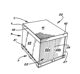
Fig. 6 is a perspective view of the container of
Fig. 1 shown in a fully set up mode.
Fig. 7 is a top plan view of a blank for the
outer wall panels of the receptacle section.
; 15 Fig. 8 is a top plan view of a blank for the
adjustable member of the receptacle section.
Fig. 9 is a top plan view of a blank for the
cover section. ~-
Fig. 10 is similar to Fig. 1 but showing a
20 second embodiment of the improved palletized container. ;~
Figs. 11-13 are perspective views of the ~ ~
~ container of Fig. 10 showing the rèceptacle section `~ ~-
i thereof in successive stages of set up.
Fig. 14 is a fragmentary perspective view of the
container of ~ig. 10 with the receptacle section thereof
in a set up mode and with portions of the outer wall
panels at one corner cut away to show the relative
disposition of the adjustable member.
Flg. 15 is similar to ~ig ~ but showing a
modified container in a fully set up mode.
:,
.~ _ 4 _
\
Fig. 16 is similar to Fig . 7 but of a modified
form of blank.
Fiy. 17 is a top plan view of the adjustable
member shown in Figs. 11-14.
~ 5 Fig. 18 is a top plan view of one of a pair of
`1 modified blanks for forming the wall panels and flap of a
receptacle section.
Referring now to the drawin~s and more
~; particularly to Figs. 1-9, one embodiment of the improved
; 10 palletized container 20 is shown. The container comprises
a collapsible receptacle section R which is mounted on the
upper surface 21 of a conventional pallet section P. The -
container 20 in a fully set up mode is shown in Fig. 6.
~¦The receptacle section R, as illustrated, is
formed from two blanks B (Fig. 7) and B' (Fig. 8) of
foldable sheet material (e.g., double-faced or double-wall
corrugated fiberboard). The sheet material may be treated
so as to be substantially moisture resistant. Blank B ~ ;
includes a plurality (e.g. four) of outer wall panels, 22,
23, 24, and 25 which are arranged in side by side relation ~
and interconnected by parallel foldline 26. A ~;
conventional manufacturer's glue flap 27 is foldably
~ connected to the exposed edge of either panel 22 or 25.
`3 Panels 22 and 24 are provided with centrally disposed
foldlines 28, each foldine 28 is in spaced parallel
relation to an adjacent foldline 26. By reason of
foldline 28, panel 22, 24 comprises a pair of panel
segments 22a-b; 24a-b which are of like configuration.
Connected by foldline 30 to the lower or
bottom-forming edye of panel 23 is an elongated flap 31
which extends substantially the distance between adjacent
.
-
r~t7~
:
~l - s -
!
foldlines 26. Flap 31 is provided with a foldline 32
which is in spaced substantially parallel relation to
foldline 30; thus, forming flap 31 into an inner segment ~
31a and an outer segment 31b. The remaining outer wall -
S panels 22, 24 and 25 may have elongated tabs 33 foldably
connected to the bottom-forming edges thereof. It will be
noted in Fig. 7 that in each instance foldline 28 extends `~
into the corresponding tab 33. The functions of flap 31
`l and tabs 33 will be described more fully hereinafter.
Blank B' defines an adjustable member 34 and
includes a pair of spaced substantially pa~allel foldlines
35, 36, see Fig. 8. ~y reason of the foldlines 35, 36,
blank B' is provided with a central bottom panel 37 and a
pair of inner side panels 38, 40. ~-
Fig. 9 shows a blank BB which forms a
telescoping cover or lid section C. When the receptacle
section R is in the collapsed mode, Fig. 1 the cover
section C is sized so that it will overlie and conceal the
`~ collapsed outer wall panels as will be discussed more -i~
; 20 fully in the description to follow. The cover section C --
may be conventional design and includes a center panel 41
~ having a configuration corresponding substantially to the
;~ area defined by the upper edges of the outer wall panels,
when the receptacle section is in the set up mode, see
Fig. 5. The center panel 41 is delimited by two pairs of
opposing foldable marginal flaps 42, 43. Each flap 42 is ~-
- provided with a pair of foldable connecting flaps 42a
which extend endwise therefrom. When the blank BB is set
up to form the cover section C, the marginal flaps 42, 43
are folded so as to depend from the central panel and form
a peripheral flange F which embraces the upper edge
? ~ ~
-6-
3 portions of the set up outer wall panels, see Fig. 6. The
connecting flaps 42a are secured by adhesive, stitching or
stapling to either the interior or exterior surface o an
adjacent marginal flap 43 and thus, retain the flaps 42,
5 43 in their flange-forming positions.
In assembling the receptacle section R on the ~-
, pallet section P, the outer segment 31b of flap 31 is
fixedly secured to the upper surface of the pallet section
by suitable fasteners (e.q. staples, nails, etc.). The
10 outer segment 31b is positioned in close proximity and -
substantially parallel to one side edge of the upper
surface. When the receptacle section R is in the set up
mode, Fig. 5, outer wall panel 23 is in substantial
vertical alignment with the adjacent side edge of the
15 pallet section upper surface 21. The remaining outer wall
panels 22, 24 and 25 are also in substantial vertical
alignment with adjacent side edges of the upper surface
21.
The central panel 37 of blank B' is configured
20 so that when receptacle section R is in the set up mode,
it will fully occupy the area defined by the set up outer
wall panels 22-25. The side panels 38 and 40 of blank B'
are disposed, respectively, in face to face relation with
3 the interior surfaces of outer wall panels~23 and 25.
25 Each eide panel conforms substantially to the shape of the
corresponding interior surface of the adjacent outer wall
panel. Side panel 38 is preferably affixed to the ~-
interior surface of wall panel 23.
When receptacle section R is being adjusted from
30 a set up mode, Fig. 5 to a collapsed mode, Fig. 1, the
side panel 40 is pulled upwardly and out of the receptacle
.;' ' ~''
.,
: :.
~- ~r~ :17~5
,
-7-
''
interior until it overlies the exterior surface of wall
panel 23, see Figs. 4, 3 and 2. When this occurs bottom
panel 37 will assume a face to face engagement with the ;~
!,: exposed interior surface of wall panel 23. In the
5 illustrated embodiment the central panel 37 and the side ;~
;; panels 38 and 40 have substantially the same configuration ~`
and side panels 38 and 40 conform substantially to the
shape of wall panels 23 and 25. Once the member 34 ;:
assumes the position shown in Fig. 2, the wall panels 22
and 24 can be pushed inwardly towards one another so that
each panel will fold about its center foldline 38 causing
the pair of panel segments 22a, 22b or 24a, 24b thereof to
~¦ assume a substantially face to face relation. As this
; occurs, wall panel 25 will automatically move towards wall
panel 23 thereby sandwiching the pairs of folded panel
' segments 22a, 22b and 24a, 24b and center panel 37 between
wall panels 23 and 25. Once the panels and panel segments
are in the aforedescribed sandwiched relation, they are
pivoted as a unit about the foldline 32 formed in flap 31.
The spacing between foldlines 30 and 32 compensated for
the thicknesses of the sandwiched panels and panel
segments, thereby allowing the panels and panel segments
to assume a substantially flat overlying relation with
respect the upper~surface~21 of the pallet section P.
Once the receptacle section R is in the collapsed mode,
the wall panels and panel segments are concealed beneath a
telescoping cover section C. As aforementioned the cover
section is formed from a blank BB of conventional design,
see Fig. 9. Once the cover section C is in place, the
,.,
.~ .
.,
,~ . 2~ t~ ~j S ~i
: `
~,!
'!~J
collapsed container forms a compact structure which may be
; readily stored in such form or shipped to a customer for
set up and loading.
Figs. 10-14 illustrate a second embodiment of
the improved container 120 which includes a pallet section
P, a receptacle section RR and a cover section C. The
pallet section P and cover section C are preferably the
same as the corresponding sections previously described
with respect to container 20. Receptacle section RR may
be formed in part from a blank B, shown in Fig. 7. In
addition, receptacle section RR includes an adjustable
~j member 134 formed from a blank BBB of foldable sheet
;i material. Blank BBB, Fig. 17 includes a pair of spaced
i substantially parallel foldlines 135, 136 which cooperate
,j 15 to form a center panel 137 and a pair of side panels 138,
140 disposed on opposite sides of the center panel. In
l addition to foldlines 135, 136, a third foldline 139 is
J formed in the blank and extends across the side and center
;i panels and is disposed substantially perpendicular to
¦ 20 foldlines 135, 136. The foldline 139 is spaced from and
substantially parallel to an edge X of the blank B~B.
When the receptacle section RR is in the set up
mode, Fig. 14, the center and side panels 137, 138 and 140
of the adjustablè member 134 are in substantially coplanar
relation and span the distance between wall panels 122,
124 so as to maintain the latter in upright substantially
parallel opposed relation~ see Fig. 14. The distance ~-
between edges X and Y of blank BBB equals substantially
the spacing between upright wall panels 123 and 125 minus ~1
',.''
',~
,:
~,
`~
the width of flap 131 measured perpendicular to the
foldline connecting the flap to the bottom forming edge of
~ wall panel 123.
;~l When assembling the adjustable member 134 and
the folded blank ~ on the pallet section P, the flap 131
is first secured to the upper surface 21 of the pallet -
section in the same manner and location as previously ~-
!' discussed with respect to container 20. The adjustable
member 134 is then positioned on the pallet section upper
surface so that the edge Y of blank ~BB is disposed in
, close proximity to, or abutting, the distal edge of flap
r¦ 131, see Fig. 14. The center panel 137 of the blank is
;1 then secured by staples, adhesive or the like to the
' pallet upper surface. Only the portion of the center
3 15 panel 137 between edge Y and foldline 139 is secured to
' the upper surface while the remainder of the blank is free
- to assume various folded positions as the receptacle
section RR is being set up or collapsed, see Figs. 11-13.
When setting up receptacle section ~R from its
2~ collapsed mode, Fig. 10, the cover section C is removed `
whereupon the stacked panels and panel segments are
pivoted as a unit to a substantially upright position,
;Fig. 11. Qnce the panels and panel segments are in the
upright position, Fig.'ll, the side panels 138, 140 of
member 134 are folded upwardly about foldlines 135, 136 so
as to partially overlap center panel 137, see Fig. 12.
The portions of the side panels 138, 140 and center panel
between edge X and foldline 139 are then folded upwardly a
small amount prior to outer wall panel 125 being pulled
away from wall panel 123. By reason of the adjustable
member 134 being initially folded as indicated, the tabs
.`' ;~ ~
- 2~17~5 S
~; j
, ~
,'f,
,~' ,
--1 o--
:...
~ .
.~ .
133 foldably connected to the bottom-forming edges of wall
,j panels 122, 124 and 125 can be readily folded so as to
overlie the pallet section upper surface 21. Once the
wall panels are set up so that each pair of panel segments
122a, 122b and 124a, 124b are in coplanar relation and the
~; tabs are overlying the upper surface, the side panels 138,
;; 140 of member 134 are unfolded so as to assume a coplanar
relation with center panel 137. Upon the side and center
panels assuming the coplanar relation, the tabs 133 are
captured between the member 134 and the pallet section
', upper surface thus, enhancing the stability o the upright
i outer wall panels. As the set up receptacle section is
filled with product, the aforementioned captured tabs will
1 remain in place.
j 15 Fig. 16 illustrates a modified blank BC which is
¦ similar to blank B, Fig. 7, except top closure flaps 150
l are foldably connected to the top-forming edges of the
^f outer wall panels 122-125. By reason of the top closure
flaps 150, the telescoping cover section C may be ` ;~
`~ 20 eliminated.
: ,
In place of having a single blank B or BC from
which the outer wall panels are formed, a pair of separate
blanks BP, only one being shown in Fig. 18, may be
utilized. Each blank BP is of like construction and ;
includes only two outer wall panels, one a side wall SW,
and the other an end wall panel EW which are
interconnected by a foldline 225. Side wall panels SW may
have a configuration similar to that of wall panel 23,
123, 25 or 125 and end wall panel EW may have a
30 configuration like that of wall panel 22, 122, 24 or 124. -
.... ................................................................... .............. " ~,,
:~
~ ^ ~n~t~S~s
Each blank BP also includes a conventional manufacturer's
glue flap 227 foldably connected to a corresponding side
edge of the blank.
It is preferred that the outer wall panels of
the receptacle section have a height such that when the
receptacle section is in the collapsed mode, no portion of
the wall panels will protrude outwardly beyond the
perimeter of the pallet section upper surface.
Thus, the improved container is of simple,
inexpensive, yet sturdy construction, and may readily and
, expeditiously be set up or collapsed with a minimum amount
~ of manual effort and without the need for special tools or
j fixtures. When in a collapsed mode, the container forms a
flat, compact structure suitable for storage and/or return
shipping for reuse.
I claim:
. :
(
. ~;~
.. ~'
:3 ~ ~
. ~
.
:
:~
'
. "~'.' '~.
`, "~ '
'~ :'
.~