Language selection

Search

Patent 2008198 Summary

Third-party information liability

Some of the information on this Web page has been provided by external sources. The Government of Canada is not responsible for the accuracy, reliability or currency of the information supplied by external sources. Users wishing to rely upon this information should consult directly with the source of the information. Content provided by external sources is not subject to official languages, privacy and accessibility requirements.

Claims and Abstract availability

Any discrepancies in the text and image of the Claims and Abstract are due to differing posting times. Text of the Claims and Abstract are posted:

  • At the time the application is open to public inspection;
  • At the time of issue of the patent (grant).
(12) Patent: (11) CA 2008198
(54) English Title: CLOSURE AND SEAL FOR PREFABRICATED BUILDING PANELS
(54) French Title: DISPOSITIF DE FERMETURE ET DE SCELLEMENT POUR PANNEAUX PREFABRIQUES
Status: Expired
Bibliographic Data
(52) Canadian Patent Classification (CPC):
  • 72/139
(51) International Patent Classification (IPC):
  • E04C 2/04 (2006.01)
  • E04B 1/68 (2006.01)
(72) Inventors :
  • SPRONKEN, JOHN R. (Canada)
(73) Owners :
  • SPRONKEN, JOHN R. (Canada)
(71) Applicants :
(74) Agent: KIRBY EADES GALE BAKER
(74) Associate agent:
(45) Issued: 1999-02-02
(22) Filed Date: 1990-01-19
(41) Open to Public Inspection: 1990-07-23
Examination requested: 1996-09-20
Availability of licence: N/A
(25) Language of filing: English

Patent Cooperation Treaty (PCT): No

(30) Application Priority Data:
Application No. Country/Territory Date
299,459 United States of America 1989-01-23

Abstracts

English Abstract


A closure and seal assembly is described for joining
the edges of concrete structural panels. The arrangement
comprises three main components, namely a pair of
elongated pocket members each adapted to be embedded in a
vertical corner of a concrete structural panel and an
elongated spline member adapted to connect between the
pocket members. Each pocket member has an inner pocket
with an elongated opening slot and a pair of resilient
sealing strips fixed to the edges of the slot and adapted
to extend into the pocket. The spline has a web portion
with T-flanges on the side edges thereof with the spline
being adapted to be snugly held between the pocket sealing
strips and the T-flanges being adapted to be held within
the pockets.


French Abstract

Assemblage de fermeture et de joint servant à relier des bords de panneaux structuraux en béton. Cet assemblage est constitué de trois composants principaux : deux éléments en forme de logements longitudinaux conçus pour s'imbriquer verticalement avec le coin d'un panneau structural en béton; et une languette longitudinale conçue pour relier ces deux logements. Chacun de ceux-ci comprend une chambre interne présentant une fente longitudinale en guise d'ouverture et une paire de joints d'étanchéité élastiques, reliés aux bords de la fente et qui se prolongent dans la chambre. La languette est formée d'une section de tissu sur les bords latéraux de laquelle sont disposées des brides en T, cette languette étant conçue pour être maintenue en place en s'imbriquant avec exactitude entre les joints d'étanchéité du logement, tandis que les brides en T sont conçues de manière à être maintenues à l'intérieur des logements.

Claims

Note: Claims are shown in the official language in which they were submitted.

-1-

Claims:
1. A closure and seal assembly for joining the edges
of prefabricated wall panels comprising:
(a) a pair of elongated pocket members each adapted to
be embedded in or fastened to a face of a prefabricated
wall panel, each pocket member having inner and outer side
walls and inner and outer end walls with said outer end
wall containing an elongated opening slot and a pair of
resilient sealing strips fixed to the edges of said slot
and adapted to extend into the pocket and at least one
vent hole extending through at least one side wall and
(b) an elongated spline member adapted to connect
between the pocket members, said spline comprising a web
portion with T-flanges on the side edges thereof and
resilient sealing strips projecting outwardly from free
edges of the T-flanges, the spline being adapted to be
snugly held between said pocket sealing strips and said
T-flanges being adapted to be held within the pockets with
said T-flange resilient sealing strips being adapted to
sealingly engage the side walls of said pocket.
2. An assembly according to claim 1 wherein each
pocket member is permanently anchored in a corner of a
pre-cast structural panel.

Description

Note: Descriptions are shown in the official language in which they were submitted.


200~1~8


Closure and Seal for Prefabricated Building Panels
Background of the Invention
This invention relates to building constructions and,
more particularly, to a closure and seal arrangement for
joining the edges of prefabricated structural panels, e.g.
wall panels.
Many different types of prefabricated panels have been
provided in the past to form walls of building structures.
Some of these prefabricated panels have included insulation
and others have included structures cast in the panels for
attaching both interior and exterior finishing panels
thereto.
Many examples of previously known pre-cast and other-
wise constructed concrete wall panels are disclosed in
U.S. Patents 723,175, 984,517, 1,445,113, 1,617,033,
2,303,837, 3,466,825,_3L605,366~ 3,605,607 and 4,112,626.
U.S. Patent 3,371,456 describes an expansion connector
for joining the edges of concrete building panels. This
connector element is in the form of a plate member with
stop members at the side edges. These stop members are
provided to limit movement of the plate member outwardly
through openings. While this connector provides a rela-
tively good structural connection between the panels, it
does not provide a good weather seal, particularly where
very strong and cold winds are involved.
It is the object of the present invention to provide a
closure and seal for joining the edges of prefabricated
wall panels which will serve as an excellent weather seal
against very strong and cold winds.

~08198
--2--

Summary of the Invention
The present invention in its broadest aspect relates to
a closure and seal for joining the edges of prefabricated
wall panels. The arrangement comprises three main compo-
nents, namely a pair of elongated pocket members eachadapted to be embedded in or fastened to the edge of a
prefabricated wall panel and an elongated spline member
adapted to connect between the pocket members. Each
pocket member has an inner pocket with an elongated
opening slot and a pair of resilient sealing strips fixed
to the edges of the slot and adapted to extend into the
pocket. The spline has a web portion with T-flanges on
the side edges thereof with the spline being adapted to be
snugly held between the pocket sealing strips and the
T-flanges being adapted to be held within the pockets.
The T-flanges may also be provided with downturned long
free side edges and these free edges of the flange may
also include outwardly projecting resilient sealing strips
which engage the inner walls of the pocket. In this
manner, a double seal is provided within the pocket.
According to another prefexred feature of the
invention, small holes are provided extending into the
pockets to serve as pressure egualizing holes. This adds
to the sealing effect of the sealing strips by ensuring
Zs that the closure and seal remain stable even if high pres~
sure exists on the inside of the building.
The closure and seal assembly of this invention may be
used for joining the edges of many different types of pre-
fabricated wall panels, such as those made of concrete,
steel, aluminum and combinations therof. With precast con-
crete panels, the assembly components may be embedded in
edges of the panels during casting. Both vertical and
horizontal edges may be joined with the assembly of the
invention.
The assembl~ of this invention has the advantages of
allowing for building movements without loss of sealing

~ 2008198
--3--

capacity and also prevents movement of air from eitherinfiltration or exfiltration.
Brief Description of the Drawings
The invention further consists in the novel arrange-
ment, combination and construction of parts more fullyhereinafter described and shown in the accompanying
drawings. In the drawings:
Fig. 1 is a perspective view showing the closure and
seal arrangement of the invention in place in a concrete
panel;
Fig. 2 is a top plan view of the arrangement shown in
Fig. l;
Fig. 3 is a top plan view of an alternative form of
panel;
lS Fig. 4 is a sectional view of a closure and seal
arrangement of the invention for connecting to panel edges;
Fig. 5 is a sectional view showing the arrangement of
Fig. 4 attached to adjacent panel edges; and
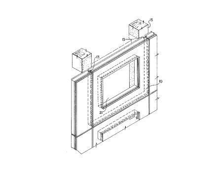
Fig. 6 is a perspective view of a wall assembly.
Description of the Preferred Embodiment
As seen in Figures 1 and 2, a pair of pre-cast concrete
panels 10 have inner side faces 11 and inner edge faces 12.
Each panel has a pocket member 13 embedded in the vertical
corner joining faces 11 and 12 and a spline 14 extends
across between the pocket members 13.
This assembly is located adjacent a column or inner
wall 15 with preferably an air gap 20 therebetween. In
this particular embodiment, the outer face of each concrete
panel 10 is covered by solid insulation 16 and a weather-
proof exterior facing 17. An expansion gap is provided
between the panels 10, insulation 16 and exterior facing
17. This gap is preferably filled by a foam plastic bead
18 and exterior caulking 19 and, if desired, is also
filled with insulation 22.
Details of the closure and seal arrangement can be best
seen from Figures 2 and 3 and it will be seen that the

~' _4_ 2ao8~98

pocket member 13 includes an exterior side panel 23, aninterior side panel 24, an interior end panel 25 and an
exterior end panel 26. Anchors 27, 28 and 29 are prefer-
ably provided for firmly anchoring the pocket member 13
within the concrete panel 10. At the exterior end of the
pocket, a pair of strips 31 provide a slot therebetween
and mounted to the free edge of each strip 31 is a resi-
lient sealing strip 30. These sealing strips 30 extend
inwardly towards each other and firmly grip the spline 14
therebetween.
The spline 14 includes a web portion 33 with edge
T-flanges 34. These flanges 34 preferably include
downwardly turned edges 35 with resilient strips 36
connected thereto. These resilient strips are directed
outwardly to engage the inner faces of the side panels 23
and 24, thereby providing additionaI sealing against wind.
Small vent holes 32 may be provided in exterior side
panels 23 of the pockets 13. These holes are positioned
to open into the gap between the resilient strips 30 and
36 and serve to equalize pressure. This adds to the
sealing effect of the sealing strips by ensuring that the
closure and seal remain stable even if high pressure
exists on the inside of the building.
The embodiment of Figure 3 is quite similar to that of
Figure 2, the main difference being that Figure 3 shows a
construction with only the pre-cast concrete panels 10 and
no insulation or outer facing. In terms of the present
invention, the embodiment of Figure 3 functions in the
8ame manner as that of Figure 2.
The closure and seal arrangement shown in Figure 4 is
intended for attaching to a flat panel surface rather than
embedding into a concrete panel. For instance, it may be
used for sealing between a prefabricated panel and a main
structure.
The embodiment of Figure 4 provides a support flange
40 for fastening to a panel face and this support flange

2~0~ 98
--5--

40 has a pair of outwardly projecting legs 41 and 42
forming therebetween a pocket. The outer ends of legs 41
and 42 have inwardly projecting strips 31 to which are
connecting resilient sealing strips 30.
The pockets are joined by a spline 14 of the type
previously described. This includes a web portion 33 with
edge T-flanges 34, which include downwardly turned edges 35
and resilient strips 36 connected thereto.
This assembly is shown in place in Figure 5 with the
connector flanges 40 mounted on structural channel members
43. These channel members 43 are mounted between a
weatherproof exterior facing 45 and an interior facing 44.
The space between exterior facing portion 45 may be filled
by a foam plastic bead 18, while the space between the
channel members 43 may be filled by insulation 47 and
further insulation 48 may be provided between the inner
and outer wall panels.
An example of the complete assembly is shown in Figure
6 and here each pre-cast concrete panel 10 is provided
with a window opening 21. It can also be seen from Figure
6 that the closure and seal pockets 13 can be positioned
at either the inner or outer face of the pre-cast concrete
panel 10. However, it is generally preferred to position
them adjacent the inner face as shown at the right hand
side of Figure 6.
While several specific forms of the invention have
been shown and described, it is to be understood that I am
to be limited only to the scope of the following claims.

Representative Drawing
A single figure which represents the drawing illustrating the invention.
Administrative Status

For a clearer understanding of the status of the application/patent presented on this page, the site Disclaimer , as well as the definitions for Patent , Administrative Status , Maintenance Fee  and Payment History  should be consulted.

Administrative Status

Title Date
Forecasted Issue Date 1999-02-02
(22) Filed 1990-01-19
(41) Open to Public Inspection 1990-07-23
Examination Requested 1996-09-20
(45) Issued 1999-02-02
Expired 2010-01-19

Abandonment History

There is no abandonment history.

Payment History

Fee Type Anniversary Year Due Date Amount Paid Paid Date
Application Fee $0.00 1990-01-19
Maintenance Fee - Application - New Act 2 1992-01-20 $50.00 1991-12-04
Maintenance Fee - Application - New Act 3 1993-01-19 $50.00 1993-01-18
Maintenance Fee - Application - New Act 4 1994-01-19 $50.00 1993-10-26
Maintenance Fee - Application - New Act 5 1995-01-19 $75.00 1994-12-12
Maintenance Fee - Application - New Act 6 1996-01-19 $75.00 1995-10-18
Maintenance Fee - Application - New Act 7 1997-01-20 $75.00 1997-01-07
Maintenance Fee - Application - New Act 8 1998-01-20 $75.00 1997-12-18
Final Fee $150.00 1998-10-26
Maintenance Fee - Application - New Act 9 1999-01-19 $75.00 1999-01-18
Maintenance Fee - Patent - New Act 10 2000-01-19 $100.00 2000-01-10
Maintenance Fee - Patent - New Act 11 2001-01-19 $100.00 2001-01-19
Maintenance Fee - Patent - New Act 12 2002-01-21 $100.00 2002-01-18
Maintenance Fee - Patent - New Act 13 2003-01-20 $100.00 2002-12-17
Maintenance Fee - Patent - New Act 14 2004-01-19 $125.00 2004-01-16
Maintenance Fee - Patent - New Act 15 2005-01-19 $225.00 2005-01-18
Maintenance Fee - Patent - New Act 16 2006-01-19 $225.00 2006-01-18
Maintenance Fee - Patent - New Act 17 2007-01-19 $225.00 2007-01-11
Maintenance Fee - Patent - New Act 18 2008-01-21 $225.00 2008-01-07
Maintenance Fee - Patent - New Act 19 2009-01-19 $225.00 2008-11-25
Owners on Record

Note: Records showing the ownership history in alphabetical order.

Current Owners on Record
SPRONKEN, JOHN R.
Past Owners on Record
None
Past Owners that do not appear in the "Owners on Record" listing will appear in other documentation within the application.
Documents

To view selected files, please enter reCAPTCHA code :


To view images, click a link in the Document Description column. To download the documents, select one or more checkboxes in the first column and then click the "Download Selected in PDF format (Zip Archive)" or the "Download Selected as Single PDF" button.

List of published and non-published patent-specific documents on the CPD .

If you have any difficulty accessing content, you can call the Client Service Centre at 1-866-997-1936 or send them an e-mail at CIPO Client Service Centre.


Document
Description 
Date
(yyyy-mm-dd) 
Number of pages   Size of Image (KB) 
Drawings 1994-04-01 4 117
Description 1994-04-01 5 205
Representative Drawing 1999-01-28 1 14
Abstract 1994-04-01 1 21
Cover Page 1994-04-01 1 14
Claims 1994-04-01 1 30
Cover Page 1999-01-28 2 67
Fees 1999-01-18 1 36
Correspondence 1998-10-26 1 44
Prosecution Correspondence 1996-09-20 1 38
Office Letter 1996-10-17 1 50
Fees 1995-10-18 1 69
Fees 1997-01-07 1 68
Fees 1993-10-26 1 58
Fees 1994-12-12 1 57
Fees 1991-12-04 2 56
Fees 1993-01-18 1 61