Note: Descriptions are shown in the official language in which they were submitted.
2008280
The present invention relates to a hydraulic propelling
apparatus for a vehicle, which utilizes a hydrostatic
transmission comprising a variable displacement hydraulic
pump and a hydraulic motor driven by pressure oil supplied
from the hydraulic pump.
Japanese Utility Model Publication Kokai No. 61-19158
dicloses an apparatus comprising a hydraulic pump having an
angularly variable swash plate, and a hydraulic motor having
an angularily fixed swash plate. In operation, the swash
plate of the hydraulic pump is rotated to cause a plurality
of pistons to deliver pressure oil to a plurality of pistons
of the hydraulic motor. As a result, the pistons of the
hydraulic are moved back and forth in fixed cycles to rotate
the swash plate of the hydraulic motor. Futhermore, the
rotational rate tranmitted to the hydraulic motor is
adjustable by-varyinq the swash plate angle of the hydraulic
pump.
A hydrostatic transmission may be used in the propelling
system of a vehicle, with the swash plate angle of the
hydraulic motor switchable for two, h,~ h
X
- ` .... - -- . -
. . ,. ~ : . ., . , :,. `: ..
,
~ 2008280
and law, speeds. In this case, the following
inconvenience may be encountered when the swash plate
angle is switched from hi8h speed to low speed while
the vehicle is running.
When the swash plate angle is switched from high
- speed to low speed, the dynamic inertial force of the
vehicle will act on the hydraulic motor. This means
that the propelling system imparts a force to rotate
the output shaft of the hydraulic motor at the rate
prevailing immediately before the swash plate angle is
switched. When the output shaft of the hydraulic
motor is rotated by the force applied from the
propelling system, the rotational rate may exceed an
aliowable rotational rate, resulting in dama8e to the
apparatus.
More particularly, when the output shaft of the
hydraulic motor is rotated in the accelerating
direction by the external force as described above,
the hydraulic motor functions as if a hydraulic pump
to discharge pressure oil. As a result, not only the
two oil lines connected to the hydraulic motor are
reversed with respect to the hi8h pressure and low
pressure sides, but the relief valve disposed between
the two oil lines is opened. This nullifies the
2$ funotion of n~ine brak- - in p-ssen~er vehiolo.
Even if the hydraulic pump operates normally, it
--2--
.
,... , . : .
.. . .
.. . . " .~ .
2~08280
inevitably allows acceleration of the output shaft as
described above, which results in damage to the apparatus.
The upper limit of the allowable rotational rate of the
hydraulic motor is set on the basis of working strokes of the
pistons within a unit time. The rotational rate occurring
when the working strokes reach a certain value is set to be
the allowable rotational rate. The upper limit of the
allowable rotational rate has a greater value when the swash
plate angle is set to the high speed than when it is set to
the low speed.
That is, where the motor of the conventional hydrostatic
transmission has two, high and low, speeds, the swash plate
of the motor may be rapidly changed from high speed to low
speed, and the dynamic inertia of the vehicle applies an
excessive load to the motor.
In one aspect, the invention provides a hydraulic
propelling apparatus for a vehicle comprising: a hydraulic
pump and a charge pump driven by a vehicle engine; a
hydraulic motor including a swash plate having a high speed
pofiition; and a swash plate low speed position, said
hydraulic motor being operatively connected to a propelling
transmission of the vehicle; a swash plate position switching
mechanism movable between a first position corresponding to
said swash plate high speed position and a second position
corresponding to said swash plate low speed position: a
three-position hydraulic control valve, a first oil pressure
~ ' ' ~ ' ` ' ~; 1, . '
:
2008280
s
supply line connected between said charge pump and said
. three-position hydraulic control valve, a second oil pressure
line connected between said three-position hydraulic control
valve and said swash plate position switching mechanism for
conducting oil under pressure to and from said swash plate
position switching mechanism; damper means comprising a
throttle mechanism in said second oil pressure line between
said three-position control valve and said swash plate
position switching mechanism, said swash plate position
switching mechanism including: a hydraulic cylinder having a
hydraulic piston movable from said first position to said
second position, and elastic means for urging said hydraulic
piston from said second position back to said first position;
said three-position hydraulic control valve controls a supply
lS oil pressure to the hydraulic cylinder for switching said
swash plate from said first swash plate position to said
second swash plate position, said hydraulic control valve
being movable between a high speed position for supplying the
hydraulic cylinder with oil pressure from said charge pump, a
low speed position for connecting the hydraulic cylinder and
said second oil pressure line with a supply tank, and a
braking position for connecting the hydraulic cylinder, said
second oil pressure line and said first oil pressure line to
the supply tank: and a negative hydraulic brake connected to
the first oil pressure line and a propelling system for
releasing a braking condition of the propelling system.
... ~ . ................... . .. ~ .
- :: .
200~280
In a preferred embodiment of the above aspect, the
hydraulic propelling apparatus further includes a one-way
control valve in a third oil pressure line which bypasses
said damper means which permits oil under pressure to flow
from said three-position control valve to said swash plate
position switching mechanism.
- 4a -
.~,
~..
- , . .. . . . ..
- . ,, -- : ~. - ,: ~ , . -
2~08~80
~ he drawings show a hydraulic propelling apparatus for a
vehicle according to the present invention, in which:-
Fig.l is a side elevation of a wheel loader equippedwith the apparatus according to the present invention,
Figs. 2A and 2B are diagrams showing hydraulic circuitry
of the wheel loader,
Fig.3 is a graph showing the allowable rotational rate
of a hydraulic motor.
Fig. 4 is a partial diagram showing modified h~draulic
circuitry, and
Fig.5 is a partial diagram showing a throttle in a
different embodiment.
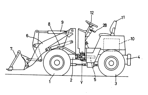
Referring to Fig.l, a wheel loader, which is one example
of vehicles, comprises a front vehicle body 2 having right
and left drive wheels 1, and a rear vehicle body 4 having
right and left drive wheels 3. The front and rear vehicle
bodies 2 and 4 are interconnected to be pivotable relative to
each other about a vertical axis Y. A steering cylinder 5 is
mounted between the front and rear vehicle bodies 2 and 4.
The front vehicle body 2 carries a shovel 7 vertically
movable by a pair of right and left arms 6,
--5
.
,.
. :' '' ' ' - ~
~ ,
': :.
2008280
lift cylinders 8 for driving the arms 6, and a tilt
cylinder 9 for driving the shovel 7. The rear body 4
carries an engine 10, a driver's seat 11, a steering
wheel 12, and a drive system for transmitting power to
the front and rear wheels 1 and 3.
The wheel loader includes a hydraulic system for
controlling the above three types of cylinders 5, 8
and 9j and a hydraulic system for driving the wheels 1
and 3 as shown in Figs. 2A and 2B, respectively.
These hydraulic systems include a variable
displacement hydraulic pump 13, a working pump 14 and
a charge pump 15 driven by the engine 10. The
variable displacement pump 13 supplies pressure oil
through oil lines 16 to a hydraulic motor 17 having a
swash plate angle switchable for two, high and low,
speeds, and an output shaft 17a connected to the
propelling system. The working pump 14 supplies
pressure oil to a control valve 18 for controlling the
steering cylinder S, a control valve 19 for
controlling the tilt cylinder 9, and a control valve
for controlling the lift cylinders 8. Part of
pressure oil from the char8e pump lS flows to an
electromagnetic valve 22 for controlling a servo
cylinder 21 which adjusts the displacement of the
variable displacement pump 13. Another part of the
pressure oil from the charge pump 15 flows to the
--6--
.., .. . . . ~ , .
,. ~ .. .
;~ :
2008280
~,
': propelling oil lines 16 as charging oil. Thef~. remaining part of the pressure oil from the charge
: pump 15 flows through a switch valve 23 to a hydraulic
cylinder 24 for switching the swash plate angle of the
: 5 hydraulic motor 17, and to a negative brake 25 mounted
in the propelling system.
The negative brake 25 is released by the pressure
:~ applied by the charge pump 15, and brakes the
:~. propelling system whenever the engine 10 is stopped.
A separate oil line 27 is provided so that the brake
25 is operable also by a foot pedal 26 during a run of
the vehicle.
. In this wheel loader, the hydraulic pump 13 and
hydraulic motor 17 constitute a stepless change speed
apparatus A. One of the forward and backward
traveling directions may be selected by operating a
cont.ol lever 28 provided laterally of the steering
wheel 12. For this purpose, a switch 29 interlocked
with the control lever 28 transmits a signal to a
control unit 30 for controlling the electromagnetic
3 valve 22.
The pressure oil from the charge pu~p 15 is
delivered to the electromagnetic valve 22 through two
oil lines 32 divided by an orifice 31, so that the
amount of operation of the servo cylinder 21 increases
with the rotational rate of the engine 10. The
. -7-
.
. .
::. . ` . .'-' ~
2008280
.
pressure oil operates the servo cylinder 21 to a
position where the differential pressure due to a
variation in the rotational rate of the engine 10
balances with a neutral spring 33 mounted in the servo
cylinder 21.
The hydraulic cylinder 24 has a hydraulic piston
24' movable by the pressure oil supplied thereto for
setting the angle of the swash plate (not shown) of
the hydraulic motor 17 to the high speed, the swash
plate ange being set to the low speed when the
pressure oil is exhausted. An oil line 35 connected
to the hydraulic cylinder 24 includes a throttle
mechanism 36 for checking a sudden and rapid switching
of the swash plate angle as described later.
~5 The switch valve 23 is movable to three
positions, i.e. a high speed position H, a low speed
position L and a parking position P.
The way in which the hydraulic circuitry of Figs.
2A and 2B operates will be described next. Assume
that, when the vehicle is running with the swash plate
angle of the hydraulic motor 17 set to the hi8h speed,
pressure oil is exhausted from the hydraulic cylinder
24 to switch the swash plate angle of the hydraulic
motor 17 to the low speed. This exhaust oil is
checked by the throttle mechanism 36, and therefore
the swash plate of the hydraulic motor 17 is switched
.~: .
~ ~ . . .. .
200~280
to the low speed relatively slowly under the force of
a spring 34. Even when this switching operation is
carried out while the vehicle is running at a
relatively high speed, the deceleration of the vehicle
due to the oil line resistance within the stepless
change speed apparatus and the mechanical resistance
of the propelling system allows the switching
operation to be completed smoothly without increasing
the rotation of the output shaft 17a of the hydraulic
motor 17 over the allowable rotational rate.
Thus, the hydraulic control system is rationally
constructed for changing the swash plate angle of the
hydraulic motor 17 for two, high and low, speeds.
This construction protects the hydraulic motor 17 from
damage even if a change speed operation is effected
through the hydraulic control system while the vehicle
is running at a relatively high speed.
Fig. 3 is a graph showing the upper limit of the
allowable rotational rate of the hydraulic motor 17
described with reference to the swash plate angle.
~- When, for example, the swash plate an81e is rapidly
changed from a high speed position H to a low speed
position L, the rotation remains below the allowable
rotational rate according to the present invention as
shown in a bro~en line arrow. In contrast, the
rotation would exceeds the upper limit of the
_g_
:. ,~ . .
... . ..
., : : ,,.: " ,,, . :: .
:~ , . : - -:
200~280
allowable rotational rate in the prior art as shown in
a phanto~ line.
The described embodiment may be modified by
including a check valve S0 connected parallel to the
throttle mechanism 36 as shown in Fig. 4, so that the
throttling action is effective only at exhaustin8
times. Further, as shown in Fig. 5, a constricted oil
line portion 60 may be formed between a control spool
and a land of the switch valve 23 for use as a
throttle.
... .
--10--
. :
.