Note: Descriptions are shown in the official language in which they were submitted.
PA~EN~ APP~ICATIO~
,
IN~ N~OR: ~OMAS ~ADE ~AI IIIN
INVEN~ON: ~XLEA,8AEILE OR~HOPEDIC B~OA~H HANI:~LE AP~ARA~US
8PECIP'ICA~ION
~ X~UN~ ~F ~ :
.. 1. ~ield of the I~vention:
The pre~ent invqn~ion relates to modular broaoh and
: handl~ assem~lies for u~e ln orthopedic lmplant su~gery.
Mor~ particularly, the pregén~ inYentlon rela~es ~o a
modular broach handle construc~lon fea~urlng a lock~ng
mech~ni~m ~or the broach that-ean be op~rated by ~urgeon
wlthout any 8pe~lal manipulative B~:epG. The locking
mechanism lnclude6 a ~rigger that move4 a slider bar o~t o~
engagement with the broach 90 the handle can easlly be
dl~connected and a 3prlng th~t allow~ the han~le to b~
locked onto the brca~h by aimply pushing the compon~nt~
tog~her.
61~60/~10/1-1-1/11
-2-
. General Background:
Releasable ~xoach or r~sp hanales h~ve been u~ed for
the purpose oP suppor~ing a r~sp ln preparin~ a bone for
receiving an implant. The handle is p~e~erably relea3able
from the ra8p following such u~e ~o other ln~truments can be
u~ed in preparlng th~ bone while the portion in~de the bone
remain~ in place d~rln~ othex ~teps.
~ypically, ~h~ broAch or raap 1~ used ~uring hlp
arthropla~ty, The gurgeon use~ ~he broach to prepare ~he
inner surfaces of the lntermedullAry canal to reoeive the
~tem of ~ femoral hip prosthe~i~. Surgical preparation o~
the intermedullary can21 de~ermines in large par~ the flt
between the ~t~m and femur and the accUrdcy of allgnment,
~he upper end of the bro~ch i~ typically de3igned 80
lS other instruman~ can f~t on ~t to prepare the upper ~rface
of he femur. ~y u~ing the broach a~ the r~fexence point,
accurate orientation o the pro~the~ls relatlve to the
prepared bo~e ~ e~sler to ach~e~e. A 8urgeon cAn also
attAch a trial neck and.head ~o t~e upper end of the broach
for perormlng a reduction ~n ordex to check rsnge of
motion, mu~cl~ tenslon, and leg l~ngth. Since hip ~urg~ry
i~ a potentlally dangerouq and ~erlous procedure, these
lnRtrume~ts muct be de~igned to provide 2 dependable
conne~tion th~t i~ ea~ to di~engage.
Releas~ble ~roach or ra~p and hAndle constructions h~ve
been developed ln t~e pa~t. Examplos ~r~ ~hown in ~.8
61560~Z10/1~
Pa~ent No. 4,306,55~, lsgued ~o For~e ~ntitled "combination
Incl~ding F~mo~al Ra~p Ar,d Calcar Faclng Reamer"t U.S.
Paten~ ~o. 4,583,270, ~ggued to ~enna, entltled "Rasp
Handle"; and ~.S. Patent No. 4,601,289, i~ued to Chla,rizzlo
et al., entitled "Femoral Trall Pro3thesl~/R~p As embly".
~ e ~orte '550 patent prov~des a construction whlch
include~ a ra~p havi~g a cutting portion and a pilot post
portlon. A handle a~embly ~ith ~ chuck releasably eng~ges
the pilot po~ portion to fa~ilitate working the ra8p into R
fem~r, A c~tter device i3 adapted t~ be ~ournaled on the
pilot po~t and pow~r driven to prepare the su~face o~ the
cslcar ~djacent the socke A~ter a ~ocke~ 15 formed in t~e
femur ~y u~e o~ a r~sp and handle assembly, the ra~p i~ left
ln the socket, the hanale as~embly ~ 6 remov~d~ and the
cutter i~ ~ournaled over the pilot post and rot~te~ by a
dxlve appaxatus, Ho~ever, the handle lnclude~ an enlongatea
txansverse portion whlch extends a~y ~rom ~he longitu~inal
axls o~ the handle~ ~ tranBV~r~e portion of this styl~ ~
while ~orkable, re~uires two hand~ to operate and extra
~anipula~i~n to move the portlon away fro~ the handle.
The Xenna '~70 patent includes a eimll~r latexa~ly
ext~nding por~lon o~ the hanale. In the Chiariz~lo et a~.
patent, a locking por~ion must pivot to a lateral po~ition
in order to dl~eng~g~ the broach ~rom the handle, po~sibly
lnter~erlng with oth~r ~ur~l~al lns~ruments. ~hese
abova-dl~cu~ed patente~ devices requlre ~ preliminar~
manipul~tion of the locklng mechanism ~n order to a~fix th~
broach to the handle.
61560/Z10/l-1-l/11
. -4-
SU~MARY OF T ~ ;
The p~esent invention provideg a ~odular broach handle
apparatus which Allow~ rele~ge of the handle ~rom the broach
slmply by t~e physici~n pulllng a tx~gger releAse located
S near the grip. Attaohment ~nd releaee i8 accompli~hed ~y a
long rigld "slider" b~r tran~la~lng in a lon~itudinal ~lot
of the handle in a ~uperiox-inferlor direction against a
compre~sion ~prin~.
~he bax has ~ po~tion near the g~lpping end of the
h~ndle which can be pulled by the phy~ician to overcome the
force of the spring and di~engdgs the handle from the
bro~ch, Enga~ement ls ach~eved simply by pushln~ the handle
ln place, the pu~hin~ force o~ercomln~ the spring and moving
the ~lider bar ~nd allowing the handle to move lnto place
~ith the ~llder ~a~ moving back lnto its eng~ement posltion
to lock the handle in place.
No par~ of th~ broach handle ~s~embly ext~nds be~ond
the roctangular outer "envelope" of the broach ~anale
assem~ly, Thi~ permit~ u~e of a~ork hammer for extraction
while th~ handle ~ 5~ill in place. The direction o~
attachment and r~lea~e i8 parallel to a c~lindrlcal
attachment pO8~ located on the superio~ ~ace of the broach.
Manual ac~uation of ~he ~lider bar is not neCe~Bary to
conneot the h~n~le to the broach, a~ pushin~ the two paxts
toge~her automatically actuates the locking mechani~m.
The pre~ent invention thus provides an l~proved bxoach
handle app~ratus for use wlth a broach h~ing a tap~red
61S60/210/1-1-1/11
--s--
configuratio~ beginnlng at a wider upper end and tapering to
a ~mall~r lower end. The apparatu~ inolude~ an elongated
handle body portion having a longitudlnal dXi3 and one end
portion de~lning a connec~ion en~ portlon for attachlng the
~roach wide upper end ~ereto. A longitudinally ext~nding
~lot extend~ a distAnce along the handle and terminates at
one end thereo~ adjacent the conne¢tion end portion of the
handl~ body.
A ~ocket communica~lng wtth the 810t and formad at the
connection end portlon of the handle body i~ provided, the
socket ~Av~ng ~n open end portion receptive o~ a~ leAst a
pa~t o~ the w$de end portion o~ the broach. A slider bAr 18
di~posed with1n ~he longi~udinal ~lot $or 611ding movement
t~erein and with re~pect to the handle be~ween eng~ged and
disenga~ed posi~ion~. The 811der bar includes an end
portion that extendY ~n~o the ~ocke~ ~hen in the engaged
po~itlon. An en~ portion o~ the 31ider bar and the handle
socket form a releasable ~onnëc ion between the broach and
the handle at ~ cyllndrlcal conn~ctlon post located on the
superior face of th~ broach. A trlgger 1~ provlded at one
end o the ~llder b~r for movlng the ~lider bar within the
lonqitudinal slot.
In the preferred embodiment, the h~ndle has an outer
3urface deflninq an "envelope~ and the longitudinal ~lot ~nd
~lider bar are contained entixely wlthin thi~ envelope. The
~lidsr bar i8 sp~ing loa~ed 80 thAt manuAl ~ctuation of the
S1560/~10/1-l-1/11
~lider bar i~ no~ neces~ary to connect the handle to the
broach, a~ pu~hlng the two parts ~broach and handle)
to~ether au~omatl~all~ act~ate8 the locklng mecha~ism. The
slider bax includes a ~rigger end portion which e,xtend~
tran~versely with re~pect to the longit~dinal axi~ of ~he
han~le r and at lea~t one tran3ver~e opening i~ pro~ide~ in
t~ handle bod~ which ~ommunicate~ wit~ the trt~ger portion
of the sllder bar, for access purposes. ~he Qocket i8
cyltndric~l having a centr~l bore corresponding to the
broach cyl~ndrical ~ttachment post, wi~h a bore axi3 that
inter~ectY ~e longitu~inal axls of the handle at an acu~e
angle.
~s
For a ~urther understanding of the nature, objects, and
ad~antages of the pres~nt invention, referenoe should be had
to the following detai~ed de~cription, taken ln con~unctlon
wi~h t~e a~comp~nying drawing~, in which l~ke reference
numeral~ denote like element~, and wherein:
Figu~e l i~ a slde ~l~w o~ the ~roac~ handle body
portlon o~ the preerrea embodiment of the app~ratus of the
pre~qn'c inventions
F~gu~e 2 i8 a bottom ~lew of the broach handle body
portlon o~ the pre~erred embodlment o~ the app~ratu~ of the
z5 present ~n~ention;
61550/210/1-1-1/ll
-7-
~igure 3 is a ~ectional vtew taken alon~ llne~ 3-3 of
Figure l;
Figure 4 i~ a ~e~tional view taken alon~ line8 4-4 o~
Pi~ure ls
Figure S i8 a ~ra~mentary ~iew of the pre~erred
embodiment of the apparatu~ of the present invention
illu~trating the ~llder bar portion th~reof~
~gure 6 i3 a top ~iew of the ~lider bar portion o~ the
preferred embodiment of the Apparat~s o the pre ent
in~ent~ont
Figure 7 1~ a side vie~ of the pre~erred embod~ment of
the apparatu6 of the preeent lnvention:
~igure 8 i9 a bottom ~iew of the pre~erred embodiment
of the apparatu~ of the present invention:
~igure 9 i8 an end view of the handle bo~y illu~tratl~g
the driving pla~form por~ion ther~of:
Figure 10 i~ a ~ide vl~w of the broach portion o~ the
pr~ferred embodl~en~ of th~ apparatu~ of the p~e8en~ -
invention~ and - ^
Figure 11 ls a top vlew of the broach portion of the
preferred embodi~ent o~ the apparatu~ of the pres~nt
in~ention taken along lines 11-11 of ~igure 10.
~ET~ILED ~ESC~lPTION OF THE PRE~ERR~ E~ODIMENTs
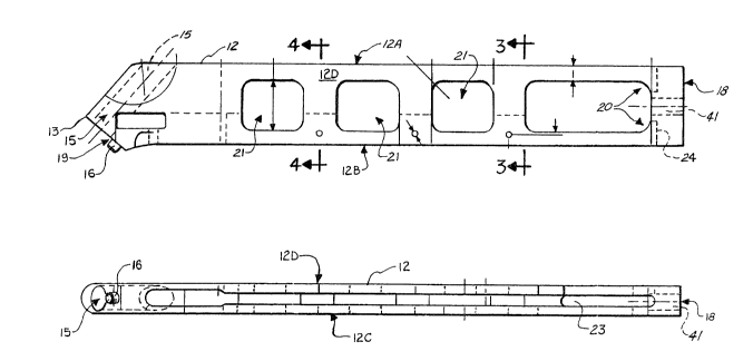
Figu~ 11 illu~trate the preferred embo~iment of
apparatus of the present in~ention which i8 deslgnated ln
5156~/210tl-1-1/11
Figures 7 ~nd ~ generally by the numeral 10. IIodul~r broacl
h~ndls apparatug 10 ~nclude~ an elongated handle body 12
ha~ing an attachment 13 end portion for a~ta~hing broach 30
there~o, a rear end portion 18 and ~ldewalls 12A - 12D.
Broach 30 (Figuses 10-11) provides a taper~d body ~avlng
wid~ upper end 38 tapering ~o smal~er end 37. Wide end
portion 38 h~s an attachment pos~ 31 which 18 generally
cyl~ndxical and i~ adap~ed ~o regl~ter w~th and ~it snugly
with~n cylindrlcal bore 15 o~rried at the ~ttachment 13 e~d
portl4n o~ handle body 12.
The attachment 13 end portion of handle body 12
include~ a generally flat face poxtion 19 which abut~ a
simlla~ flat ~ace portion 32 of broach 30. ~n allgnment
~tud 16 extenas away ~ro~ ~urface 19 and i~ 3ized to
lS regi~ter and flt wlthin the alignm~n~ hole 33 of broach 30.
~he end portion 17 ~paoed a~ay rom attaohment ~nd 13 o~
handle ~ody 12 deflne~ a drivlng pl~t~orm 17 which can be
generally rec~anyular (~ee Figure 9), an~ ~hich affixes to
han~lo body 12 at its rearmost ~a~e 18.
Handle body 12 provide~ a tran~v~rse openlng 20
extend~ng longitudinally ~ee Flgure 7) a dist~nce to
accommodate the finger of a surgeon ~or moving slider bar 22
fore and aft wlth r~spec~ to handle body 12. A plur~lity o~
~dditional opening~ 21 can ~e provided extending
trans~er~ely through handle body 12 ~or reduc1ng the weight
o~ handle body ~2.
61560~210/1-1-1/11
- 9 -
Handle body la has a longitudinally extending alot 23
which ex~ends aubstantially the leng~h of hAndle body 1~
~erminating at rea~most stop 24 and extending ~orwardly to
meet c~lind~ic~l bore lS.
In the preferred embodiment, the longitudlnally
extending slo~ 23 op~n~ to the b~ttom ~urface 12~ of handle
bod~ 12 ~or facllit2~.ing assembly of slider ~ar 22 into
handle body lZ and more part~cula~ly ln~o the longitudi~ally
extending ~lo~ ~3 portion thereo~. sllder bar 22 (Fig~res
5-6) includes an elongated llnear portion, generally
rectangul2r in ~e~tion, beglnn~ng at end 25 a~d ~ermlnat1ng
at 26. A trigger 27 lncluaes a gripping ~urface portlon 28
which i~ r~eptive of ~he flnger of a surgeon. T~igger 28
l~cludes ~pring CRrrier 29 which carrle~ a coil 6pring 40
(Flgure 7) during operation. ~ ~pring 30cket 41 1~ provlded
~n handle bod~ 12 extending from the transver~e opening 20
rearwardly to rear end portion 18 of han~le body 12.
~andle body 12 include~ an ~pper longi~ud~nally
ex~en~ing ~lot 43 which deflne~ a stop 44 limitln~ the
forward movement of slide~ m~mber 22 and a ~top 46 llmiting
the re~rwar~ movement of slider member ~2. The slidex bar
i8 free to tran~late longitudinally in a sllding fa~hlon
~ith r~3pect to the handle bo~y 12 in both directions as
shown by the bl-d~xection~l arro~ 45 ln ~igure 7~
A plurality o~ open~.ng3 47 def~ne pin opening~ for
receiving a~embly pln~ P, generally cylindri~al ln 3hape
61560/210/1~
-la-
whi~h axe placed within op~nin~s 47 after 31i~er bar 22 19
placed ln a~ operative pogi~ion, a~ ~hown in FlgUre 7. The
a~se~bly plns P can slmply be forco flt ~nto posltion or
held in place by m~ans of cement, wel~ing or the like.
~he pre~nt ~nvention provide~ a releasable conne~tion
whi~h au~omAtically connec~3 broaah 30 to hanale body 12
when post 31 18 placed into bore 15 in a dlrection ~hich
secure~ Alignment pln 16 ~nto op~ning 33 of broach 30 and
which places ~e a8~mbly faces 19 ~nd 32 together in a
fa~e-to-~ac~ matlnq rel~tion~hip.
~ec~use the slider bar 22 move~ longitudlnally wlthin
~lot 23, the end 25 portion of ~llder bar 22 1~ pushed
rear~ardly moving triqge~ ~7 toward handle body end portlon
18. Howe~er, when the GUtermO~t end 35 of as~em~l~ po~t 31
p~ne~rates ~ully into boxe 15, end 2S of ~lider bar 22
register~ with re~e~s 36 whlch 18 ~mila~ly sh~ped to end
poxtion 25 so that a conne~tion is formed between handle
body 12 and broach 30 without the need for manlp~lation by
the surgeon o~ the sllder bar 22 ~n~ its trigger ~7. Thu~,
the lock~ ng mechanl6m for~ed by end 25 of slider b~r 22
xegi~terin~ with rece~s 36 of po~t 31 1B au~omatic ~imply by
~orclng the bro~ch and ~he handle bod~ toge~her, pu~hing the
~wo paxts 12, 30 together ~hile regl~t~ring po~t 31 into
bore 15 and stud 16 into opening 33.
2S Upon a~embly, the surgeon can th~n use the handle body
12 to manipulate the lowermo~t, naxrow end portion 37 o~
615~0/210/1-1-1/11
broacll 30 into the lnt~rmedullary can~l a~ part . of the
~urgical procedure. The oppo~i~e 38 wldc en~ portion of
~ro~ch 30 i8 conn~cted ~o the h~ndle until the surgeon pulls
trigger 27 in a reaxward direction, toward driving platform
17 which compre3se~ coil spxlng 40.
The apparatu~ of the present inventlon aan b~
manuf~ctured o~ any suitable ~x~ctural material, 8uch a~
ti~anium, ~tainless s~eel, or the like, and/or any o~her
metalli~ contruction Which 1~ us~ful for the manufActure of
~urgical instruments.
~ n v~ew of the numersu~ modifio~tions ~hich oould be
mQde to the pre~erred embodlment~ di3clo~ed herein without
departing from ~he scope or 3pirit o~ the present invention,
the detail~ herein are to be in~e~pr~ted A8 illu~tratlve and
not in a limi~lng 8en3e.
Wh~t ~ clai~ed a~ invention 1
61560~210/1