Note: Descriptions are shown in the official language in which they were submitted.
2~08~14
REFASTENABLE MECHANICAL FASTENING SYSTEM AND
PROCESS OF MANUFACTURE THEREFOR
FIELD OF THE INVENTION
The present invention relates to refastenable mechanical
fastening systems, more particularly to fastening systems having
free formed prongs and the process of manufacturing such fastening
systems.
BACKGROUND OF THE INVENTION
0 Refastenable mechanical fastening systems are well known in
the art. Typically, such fasteninq systems involve two major
components, a prong which is joined to a substrate and engages
with a complementary second component, the receiving surface. A
projection of the prong of the fastening system penetrates the
receiving surface and either engages or intercepts strands or
fibers of the receiving surface. The resulting mechanical
interference and physical obstruction prevent removal of the
fastening system from the receiving surface until the separation
forces exceed either the peel or shear strength of the fastening
system.
230861 4
Presently, refastenable merh~n;cal fastening systems
are made by at least two general methods. One method
requires a plurality of filaments, each of which may be
formed into two prongs. Examples of fastening systems
produced by this method are shown in U.S. Patent No.
2,717,437, issued September 13, 1955 to de Mesteral and
U.S. Patent No. 3,943,981, issued March 16, 1976 to De
Brabandar which teach a raised pile of loops. Related
teachings are shown in U.S. Patent No. 4,216,257, issued
August 5, 1980 to Schams et al., U.S. Patent No. 4,454,183,
issued June 12, 1984 to Wollman and U.S. Patent No.
4,463,486, issued August 7, 1984 to Matsuda. These
references teach heating the ends of polymeric
monofilaments. Other related teachings of fastening
systems produced by the first method are disclosed in U.S.
Patent No. 4,307,493, issued December 29, 1981 to Ochiai
and U.S. Patent No. 4,330,907, issued May 25, 1982 to
Ochiai.
The second general method commonly utilized to
manufacture m~ch~nical fastening systems is to mold or
extrude the systems as illustrated in U.S. Patent No.
3,147,528, issued September 8, 1964 to Erb and U.S. Patent
No. 3,594,863, issued July 27, 1971 to Erb. Continuous
injection molding is taught in U.S. Patent No. 3,594,865,
issued July 27, 1971 to Erb.
Various prong structures are illustrated in the prior
art. For example, the references discussed above teach
fastening systems having stems of generally constant cross
section. U.S. Patent No. 3,708,833, issued January 9, 1973
to Ribich et al discloses a prong which is somewhat tapered
from the proximal end to the distal end and perpendicularly
projects from the substrate.
A European Patent Application published under No.
0,276.970 on August 3, 1988, by The Procter & Gamble
Company, discloses a fastening device having a constant
cross section stem oriented at an angle between about 30
and about 90 relative to the base.
~,
20086 1 4
The prior art does not show methods of manufacture
which produce free formed prongs. The prior art also does
not show the structure of a mech~n;cal fastening system
wherein the prong is nonperpendicularly oriented relative
to the substrate and has tapered sides.
It is an object of an aspect of this invention to
provide a free formed mechanical fastening system produced
by a method of manufacture similar to gravure printing. It
is an object of an aspect of this invention to provide a
fastening system having tapered prongs which do not
perpendicularly project from the associated substrate.
BRIEF SUMMARY OF THE INVENTION
The invention comprises a fastening system for
attaching to a complementary receiving surface. The
fastening system has a substrate and at least one free
formed prong comprising a base, shank and engaging means.
The base of the prong is joined to the substrate and the
shank is contiguous with and projects outwardly from the
base. The engaging means is joined to the shank and
projects laterally beyond the periphery of the shank. The
shank is nonperpendicularly oriented relative to the plane
of the substrate. The shank has a leading edge and a
trailing edge defining a leading angle and trailing angle
respectively. The leading angle and trailing angle are
substantially different from each other, so that the sides
of the shank are nonparallel.
The fastening system may be made according to the
process comprising the steps of heating a thermally
sensitive material sufficiently to reduce its viscosity for
processing, and preferably to at least its melting point.
A means to deposit discrete amounts of the heated material
is provided. The substrate to which the material is to be
joined is transported in a first direction relative to the
means for depositing the material. The material is
deposited on the transported substrate in discrete amounts.
The discrete amount of material are then stretched in a
3a 2 0 ~ 8 6 1 4
direction having a component generally parallel to the
plane of the substrate and the stretched material is
severed to form a distal end and engaging means.
s Other aspects of this invention are follows:
A process for making a fastening system comprising
one or more free formed prongs, the process comprising
the steps of:
providing a molten thermally sensitive material;
providing a substrate;
transporting said substrate in a first direction;
depositing discrete amounts of said molten
thermally sensitive material on said transported
substrate;
stretching a portion of said discrete amount of
said molten thermally sensitive material in a direction
having a component parallel to the plane of said
substrate so as to form a prong and a moil;
severing said moil from said stretched molten
thermally sensitive material to leave said prong; and
solidifying said molten thermally sensitive
material of said prong, said prong having a base, a
shank and an engaging means.
A process for making free formed prongs useful as a
component of a fastening system, the process comprising
the steps of:
providing a molten thermally sensitive material;
providing a substrate;
depositing discrete amounts of said molten
thermally sensitive material on said substrate;
stretching a portion of said discrete amount of
said molten thermally sensitive material in a direction
having a vector component parallel to the plane of said
substrate so as to form a prong; and
~ 3b 20086 1 4
solidifying said molten thermally sensitive
material of said prong, said prong having a base, a
shank, and an engaging means.
A process for making a fastening system comprising
an array of free formed prongs, the process comprising
the steps of:
providing a molten thermally sensitive material;
providing a substrate;
transporting said substrate in a first direction;
providing a print roll adapted to rotate about its
centerline, which centerline is disposed generally
parallel to the plane of said substrate and generally
perpendicular to the first direction of transport of
said substrate, said print roll having cells disposed in
its periphery;
providing a backing roll having a centerline
disposed generally parallel to said centerline of said
print roll, said print roll and said backing roll
juxtaposed to form a nip therebetween;
transporting said substrate through said nip
between said print roll and said backing roll;
disposing said molten thermally sensitive material
in said cell of said print roll;
depositing discrete amounts of said molten
thermally sensitive material on said transported
substrate by rotating said print roll until said cell
containing said molten thermally sensitive material
contacts said substrate so as to transfer said molten
thermally sensitive material onto said substrate;
stretching said discrete amounts of said molten
thermally sensitive material in a direction having a
component parallel to the plane of said substrate due to
the relative displacement between said substrate and
said cell as said print roll and said backing roll
... .
3 20086 1 4
continue to rotate and said substrate is transported so
as to form a prong and a moil;
severing said prong from said print roll so as to
divide said molten thermally sensitive material into
said prong and said moil; and
solidifying said molten thermally sensitive
material of said prongs, said prong having a base, a
shank, and an engaging means.
A process for making a fastening system comprising
one or more free formed prongs, the process comprising
the steps of:
providing a molten thermally sensitive material;
providing a substrate;
transporting said substrate in a first direction;
depositing discrete amounts of said molten
thermally sensitive material on said transported
substrate;
stretching a portion of said discrete amount of
said molten thermally sensitive material in a direction
having a component parallel to the plane of said
substrate so as to form a prong and a moil;
severing said moil from said stretched molten
thermally sensitive material to leave said prong;
solidifying said molten thermally sensitive
material of said prong, said prong having a base, a
shank and an engaging means; and
establishing a second stage temperature
differential across said solidified prong so as to
change the orientation of said engaging means.
A process for making a fastening system comprising
one or more free formed prongs, the process comprising
the steps of:
providing a thermally sensitive material;
providing a substrate;
transporting said substrate in a first direction;
20086 1 4
3d
providing a print roll adapted to rotate about its
centerline, which centerline is disposed generally
parallel to the plane of said substrate and generally
perpendicular to the first direction of transport of
said substrate, said print roll having at least one cell
disposed in its periphery;
disposing said molten thermally sensitive material
in said cell;
providing a backing roll having a centerline
generally disposed parallel to said centerline of said
print roll;
juxtaposing said print roll and said backing roll
to form a nip therebetween;
rotating said print roll and said backing roll at a
substantially equal surface velocity at said nip,
wherein said substrate is transported through said nip
in the first direction;
rotating said print roll until said cell containing
said molten thermally sensitive material contacts said
substrate;
transferring said molten thermally sensitive
material from said cell onto said substrate;
stretching a portion of said discrete amount of
said molten thermally sensitive material in a direction
having a component parallel to the plane of said
substrate so as to form a prong and a moil;
severing said moil from said stretched molten
thermally sensitive material to leave said prong;
solidifying said molten thermally sensitive
material of said prong, said prong having a base, a
shank and an engaging means; and
establishing a second stage temperature
differential across said solidified prong so as to
change the orientation of said engaging means.
20086 1 4
3e
A process for making a fastening system comprising
one or more free formed prongs, the process comprising
the steps of:
providing a thermally sensitive material;
providing a substrate;
transporting said substrate in a first direction;
providing a print roll adapted to rotate about its
centerline, which centerline is disposed generally
parallel to the plane of said substrate and generally
perpendicular to the first direction of transport of
said substrate, said print roll having at least one cell
disposed in its periphery;
disposing said molten thermally sensitive material
in said cell;
providing a backing roll having a centerline
generally disposed parallel to said centerline of said
print roll;
juxtaposing said print roll and said backing roll
to form a nip therebetween;
rotating said print roll and said backing roll at a
substantially equal surface velocity at said nip,
wherein said substrate is transported through said nip
in the first direction, said substrate having a velocity
from about 2% to about 10% greater than the surface
velocity of said print roll and said backing roll;
rotating said print roll until said cell containing
said molten thermally sensitive material contacts said
substrate;
transferring said molten thermally sensitive
material from said cell onto said substrate;
stretching a portion of said discrete amount of
said molten thermally sensitive material in a direction
having a component parallel to the plane of said
substrate so as to form a prong and a moil;
200861 4
3f
severing said moil from said stretched molten
thermally sensitive material to leave said prong; and
solidifying said molten thermally sensitive
material of said prong, said prong having a base, a
shank and an engaging means.
A process for making a fastening system comprising
an array of free formed prongs, the process comprising
the steps of:
providing a molten thermally sensitive material;
providing a substrate;
transporting said substrate in a first direction;
providing a print roll adapted to rotate about its
centerline, which centerline is disposed generally
parallel to the plane of said substrate and generally
perpendicular to the first direction of transport of
said substrate, said print roll having cells disposed in
its periphery;
providing a backing roll having a centerline
disposed generally parallel to said centerline of said
print roll, said print roll and said backing roll
juxtaposed to form a nip therebetween;
transporting said substrate through said nip
between said print roll and said backing roll;
disposing said molten thermally sensitive material
in said cell of said print roll by contacting said print
roll with said molten thermally sensitive material and
wiping and/or scraping excess material from said print
roll as said print roll is rotated by using a doctor
blade positioned in juxtapositional relationship with
the periphery of said print roll;
depositing discrete amounts of said molten
thermally sensitive material on said transported
substrate by rotating said print roll until such cell
containing said molten thermally sensitive material
;
2 008 6 1 4
3g
contacts said substrate so as to transfer said molten
thermally sensitive material on the substrate;
stretching said discrete amounts of said molten
thermally sensitive material in a direction having a
component parallel to the plane of said substrate to the
relative displacement between said substrate and said
cell as said print roll and said backing roll continue
to rotate and said substrate is transported so as to
form a prong and a moil;
severing said prong from said print roll by
intercepting said molten thermally sensitive material
with a stationary severing means for severing said
molten thermally sensitive material so as to divide said
molten thermally sensitive material into said prong and
said moil, said severing means comprising a heated wire
disposed substantially across said substrate and
parallel to said centerline of said print roll, wherein
said wire is heated to a temperature of at least a
melting point of said thermally sensitive material;
solidifying said molten thermally sensitive
material of said prongs by differentially cooling said
prong such that said thermally sensitive material
contracts and shrinks at different rates to curl said
thermally sensitive material at said engaging means,
said prong having a base, a shank, and an engaging
means; and
establishing a second stage temperature
differential across said solidified prong so as to
change the orientation of said engaging means.
A free formed prong manufactured according to a
method comprising the steps of:
providing a molten thermally sensitive material;
providing a substrate;
depositing discrete amounts of said molten
thermally sensitive material on said substrate;
20086 1 4
3h
stretching a portion of said discrete amount of
said molten thermally sensitive material in a direction
having a vector component parallel to the plane of
substrate so as to form a prong; and
solidifying said molten thermally sensitive
material of said prong, said prong having a base, a
shank, and an engaging means.
A fastening system for attaching to a complimentary
receiving surface, said fastening system being
manufactured according to the method comprising the
steps of:
providing a molten thermally sensitive material;
providing a substrate;
transporting said substrate in a first direction;
depositing discrete amounts of said molten
thermally sensitive material on said transported
substrate;
stretching a portion of said discrete amount of
said molten thermally sensitive material in a direction
having a component parallel to the plane of said
substrate so as to form a prong and a moil;
severing said moil from said stretched molten
thermally sensitive material to leave said prong; and
solidifying said molten thermally sensitive
material of said prong, said base prong having a base, a
shank, and an engaging means.
A fastening system for attaching to a complimentary
receiving surface, said fastening system being
manufactured according to the method comprising the
steps of:
providing a molten thermally sensitive material;
providing a substrate;
transporting said substrate in a first direction;
providing a print roll adapted to rotate about its
centerline, which centerline is disposed generally
~ ",~
c~, -
- 3i 20086 ~ 4
parallel to the plane of said substrate and generally
perpendicular to the first direction of transport of
said substrate, said print roll having cells disposed in
its periphery;
providing a backing roll having a centerline
disposed generally parallel to said centerline of said
print roll, said print roll and said backing roll
juxtaposed to form a nip therebetween;
transporting said substrate through said nip
between said print roll and said backing roll;
disposing said molten thermally sensitive material
in said cell of said print roll;
depositing discrete amounts of said molten
thermally sensitive material on said transported
substrate by rotating said print roll until said cell
containing said molten thermally sensitive material
contacts said substrate so as to transfer said molten
thermally sensitive material onto said substrate;
stretching said discrete amounts of said molten
thermally sensitive material in a direction having a
component parallel to the plane of said substrate due to
the relative displacement between said substrate and
said cell as said print roll and said backing roll
continue to rotate and said substrate is transported so
as to form a prong and a moil;
severing said prong from said print roll so as to
divide said thermally sensitive material into said prong
and said moil; and
solidifying said molten thermally sensitive
material of said prongs, said prong having a base, a
shank, and an engaging means.
200861 4
An illustrative and suitable, but nonlimiting, use
for the fastening system produced by the process of the
present invention is in conjunction with a disposable
absorbent garment, such as a diaper. This example of
one usage of the present invention is more fully
described below.
BRIEF DESCRIPTION OF THE DRAWINGS
While the Specification concludes with claims
particularly pointing out and distinctly claiming the
invention, it is believed the invention will be better
understood from the following description taken in
conjunction with the associated drawings in which like
elements are described by the same reference numeral and
related elements are designated by adding one or more
prime symbols or incrementing the numeral by 100-
Figure 1 is a perspective view of a fastening
system of the present invention wherein the engaging
means are oriented in substantially the same direction;
Figure 2 is a side elevational view of one prong of
the fastening system shown in Figure 1;
Figure 3 is a side elevational view of a second
embodiment having a generally semispherically shaped
engaging means;
Figure 4 is a side elevational schematic view of
one apparatus which can be used to produce the fastening
system of the present invention;
Figure 5 is a perspective view of a fastening
system of the present invention wherein the engaging
means are oriented in substantially random directions;
and
Figure 6 is a perspective view of a disposable
absorbent utilizing the fastening system of the present
invention, showing the topsheet and core partially in
cutaway.
200 8 6 1 ~
DETAILED DESCRIPTION OF THE INVENTION
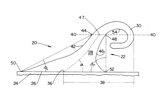
The fastening system 20 of the present invention
comprises at least one prong 22, and preferably an array
of prongs 22, joined to a substrate 24 in a
predetermined pattern as shown in Figure 1. The prongs
22 have a base 26, shank 28 and engaging means 30. The
bases 26 of the prongs 22 contact and adhere to the
substrate 24, and support the proximal ends of the
shanks 28. The shanks 28 project outwardly from the
substrate 24 and bases 26. The shanks 28 terminate at a
distal end which is joined to an engaging means 30. The
engaging means 30 radially project laterally from the
shanks 28 in one or more directions and may resemble a
hook-shaped tine. As used herein, the term "lateral"
means having a vector component generally parallel to
the plane of the substrate 24 at the principal prong 22
under consideration. The projection of an engaging
means 30 from the shank 28 periphery in a lateral
direction allows the engaging means 30 to be secured to
a complementary receiving surface (not shown). The
engaging means 30 is joined to, and preferably
contiguous with, the distal end of the prong 22. It
will be apparent the engaging means 30 may be joined to
the prong 22 at a position between the base 26 and the
distal end of the shank 28.
The array of prongs 22 may be produced by any
suitable method, including methods which yield a free
formed prong 22 as described and claimed hereinbelow.
As used herein, the term "free formed" means a structure
which is not removed from a mold cavity or extrusion die
in solid form or with a defined shape. The prongs 22
are deposited onto a noncontiguous substrate 24 in a
molten, preferably liquid state and solidify, by cooling
until rigid and preferably freezing, into the desired
structure and shape as described hereinafter.
6 2008~ 1 4
The free formed array of prongs 22 is preferably
produced by a manufacturing process which is similar to
that process commonly known as gravure printing. Using
this process, a substrate 24 having opposed faces is
passed between the nip 70 of two generally cylindrical
rolls, a print roll 72 and a backing roll 74, as
illustrated at Figure 4. The rolls 72 and 74 have
generally parallel centerlines and are maintained in
contacting relationship with the substrate 24 as it
passes through the nip 70. One of the rolls, referred
to as the print roll 72, has an array of blind, closed-
end cavities, referred to as cells 76, corresponding to
the desired pattern of prongs 22 to be deposited on the
substrate 24. The second roll, referred to as the
backing roll 74, provides the reaction against the print
roll 72 to position the substrate 24 against the print
roll 72 as the substrate 24 passes through the nip 70.
Liquid, thermally sensitive material, preferably
thermoplastic material, from which the prongs 22 are to
be formed is supplied from a heated source, such as a
trough 80. The thermally sensitive material is
introduced into the cells 76 as the print roll 72 is
rotated about its centerline. The cells 76 containing
the thermally sensitive material transport it until
contact with the substrate 24 is made and deposit this
material onto the substrate 24 in the desired pattern.
As relative displacement between the substrate 24
and rolls 72 and 74 continues, the prongs 22 are
stretched with a lateral component, generally parallel
to the plane of the substrate 24, forming the shank 28
and the engaging means 30. Finally, the moil of the
prong 22 is severed from the engaging means 30 by a
severing means 78. Due to the viscoelastic properties
of the thermoplastic, the prong 22 retracts under the
influences of gravity and shrinkage which occur during
cooling. The prong 22 then cools, and preferably
~`~r
6a 2 0 0 8 6 ~ 4
freezes, into a solid structure having the engaging
means 30 contiguous with the shank 28.
The fastening system 20 is secured to a
complementary receiving surface. As used herein, the
term "receiving surface" to which the engaging means 30
of the fastening system 20 are secured refers to any
plane or surface having an exposed face with tightly
spaced openings complementary to the engaging means 30
and defined by one or more strands or fibers or,
alternatively, which exposed face is capable of
localized elastic deformation so that the engaging means
30 may become entrapped and not withdrawn without
interference. The openings or localized elastic
deformations allow for entry of the engaging means 30
into the plane of the receiving surface, while the
strands (or nondeformed material) of the receiving
surface interposed between the openings (or deformed
areas) prevent withdrawal or release of the fastening
i
7 20086 1 4
system 20 until desired by the user or either the peel
or shear strength of the fastening system 20 is
otherwise exceeded. The plane of the receiving surface
may be flat or curved.
A receiving surface having strands or fibers, is
said to be "complementary" if the openings between
strands or fibers are sized to allow at least one
engaging means 30 to penetrate into the plane of the
receiving surface, and the strands are sized to be
engaged or intercepted by the engaging means 30. A
receiving surface which is locally deformable is said to
be "complementary" if at least one engaging means 30 is
able to cause a localized disturbance to the plane of
the receiving surface, which disturbance resists removal
or separation of the fastening system 20 from the
receiving surface.
Suitable receiving surfaces include reticulated
foams, knitted fabrics, nonwoven materials, and
stitchbonded loop materials, such as VelcroTM brand loop
materials sold by Velcro USA of Manchester, New
Hampshire. A particularly suitable receiving surface is
stitchbonded fabric Number 970026 sold by the Milliken
Company of Spartanburg, South Carolina.
Referring back to Figure 2 to examine the
components of the fastening system 20 in more detail,
the substrate 24 of the fastening system 20 should be
strong enough to preclude tearing and separation between
individual prongs 22 of the fastening system 20, be a
surface to which the prongs 22 will readily adhere and
be capable of being joined to an article to be secured
as desired by a user. As used herein the term "join"
refers to the condition where a first member, or
component, is affixed, or connected to a second member
or component, either directly; or indirectly, where the
first member or component is affixed or connected to an
intermediate member, or component which in turn is
7a ~ O 8 ~ ~ ~
affixed, or connected, to the second member or
component. The association between the first member, or
component, and the second member, or component, is
S intended to remain for the life of the article. The
"substrate" is any ~Ypose~ surface to which one or more
prongs 22 are joined.
~ 3
8 20C861 4
The substrate 24 should also be capable of being
rolled, to support conventional manufacturing processes,
flexible so that the substrate 24 may be bent or flexed
in a desired configuration, and able to withstand the
heat of the liquid prongs 22 being deposited thereon
without melting or incurring deleterious effects until
such prongs 22 freeze. The substrate 24 should also be
available in a variety of widths. Suitable substrates
24 include knitted fabric, woven materials, nonwoven
materials, rubber, vinyl, films, particularly
polyolefinic films and preferably kraft paper. White
kraft paper having a basis weight of 0.08 kilograms per
square meter (50 pounds per 3,000 square feet) has been
found suitable.
The base 26 is the generally planar portion of the
prong 22 which is attached to the substrate 24 and is
contiguous with the proximal end of the shank 28 of the
prong. As used herein, the term "base" refers to that
portion of the prong 22 which is in direct contact with
the substrate 24 and supports the shank 28 of the prong
22. It is not necessary that a demarcation be apparent
between the base 26 and the shank 28. It is only
important that the shank 28 not separate from the base
26 and that the base 26 not separate from the substrate
24 during use. The base 26 cross section should provide
sufficient structural integrity, and hence area, for the
desired peel and shear strengths of the fastening system
20, based on the density of the pattern of prongs 22 and
length of the shanks 28 of the individual prongs 22 and
further provide adequate adhesion to the substrate 24.
If a longer shank 28 is utilized, the base 26 should
generally be of greater cross sectional are to provide
sufficient adhesion to the substrate 24 and adequate
structural integrity.
The shape of the footprint of the base 26 on the
substrate 24 is not critical, and may be amplified in
~, .
- 9 20~86 1 4
any direction to provide greater structural integrity
and thus a greater peel strength in that direction. As
used herein, the term "footprint" refers to the planar
contact area of the base 26 on the substrate 24. The
aspect ratio of the sides of the footprint should not be
too great, otherwise the prong 22 may be unstable when
subjected to forces parallel to the shorter side of the
footprint. An aspect ratio of less than about 1.5:1 is
preferred, and a generally circular footprint is more
preferred.
For the embodiment described herein, a base 26
having a footprint of generally circular shape and
approximately 0.76 millimeters to 1.27 millimeters
(0.030 to 0.050 inches) in diameter is suitable. If it
is desired to make the fastening system 20 have a
greater peel or shear strength in a particular
direction, the cross sectional area of the base 26 may
be modified to amplify such direction, so that the
strength and structural integrity relative to the axis
orthogonal to such direction increases. This
modification causes the prongs 22 to be stronger when
pulled in the amplified direction of the base 26.
The shank 28 is contiguous with the base 26 and
projects outwardly from the base 26 and substrate 24.
As used herein, the term "shank" refers to that portion
of the prong 22 which is intermediate of and contiguous
with the base 26 and the engaging means 30. The shank
28 provides longitudinal spacing of the engaging means
30 from the substrate 24. As used herein, the term
"longitudinal" means in a direction having a vector
component away from the substrate 24, which direction
increases the perpendicular distance to the plane of the
substrate 24 at the base 26 of the prong 22, unless
otherwise specified to be a direction having a vector
component towards such plane of the substrate 24.
'~
~..
2~0861 4
Associated with the shank 28 and base 26 of each
prong 22 is an origin 36. The "origin" of the shank 28
is the point which may be thought of as the center of
the base 26, and is typically within the footprint of
the base 26. The origin 36 is found by viewing the
prong 22, from the side view. The "side view" is any
direction radially towards the shank 28 and base 26
which is also parallel to the plane of the substrate 24.
If the fastening system 20 is manufactured by the
process described and claimed below, it is preferred,
but not necessary, that the prong 22 be viewed in the
machine end cross-machine directions, relative to the
travel of the substrate 24 through the nip 70, when
determining the origin 36.
The lateral distance between the remote edges of
the base 26 footprint for the particular side view under
consideration is found, and this distance is bisected,
yielding the midpoint of the base 26 for such view.
When bisecting the footprint of the base 26 for the
particular side view under consideration, minor
discontinuities (such as fillets or asperities incident
to the attachment to substrate 24) are ignored. This
point is the origin 36 of the shank 28.
The shank 28 makes an angle ~ with the plane of the
substrate 24. As used herein, the term "plane of the
substrate" refers to the flat, planar surface of the
substrate 24 at the base 26 of the principal prong 22
under consideration. The angle ~ is determined as
follows. The prong 22 is viewed in profile. The
"profile view" of the prong 22 is one of two particular
side views and found as follows. The prong 22 is
visually inspected from the side views such that the
direction having the maximum lateral projection 38
becomes apparent. The "lateral projection" is the
distance taken laterally and parallel to the plane of
the substrate 24 from the center of the base 26 in such
.....
2 0 D8 6 ~ ~
view, i.e. the origin 36 of the shank 28, to the
projection of the furthest laterally remote point on the
prong 22 visible in such view when such point is
longitudinally and perpendicularly projected downward to
the plane of the substrate 24.
It will be apparent to one skilled in the art that
the maximum lateral projection 38 is that projection
from the origin 36 to the outer periphery of the shank
28 or engaging means 30. The side view of the prong 22
which maximizes the lateral projection 38 is the profile
view of such prong 22. It will also be apparent to one
skilled in the art that if the fastening system 20 is
produced by the process described and claimed below, the
maximum lateral projection 38 is generally oriented in
the machine direction and, hence, the profile view is
generally oriented in the cross-machine direction. The
side elevational view shown in Figure 2 is one of the
profile views of the prong 22. It will be further
apparent to one skilled in the art that there is another
profile view, generally 180 opposite from the profile
view shown (so that the maximum lateral projection 38 is
oriented towards the left of the viewer). Either of the
two profile views is generally equally well suited for
the procedures and usages described hereinbelow.
The origin 36 of the shank 28 is found, as
described above, with the prong 22 in the profile view.
While still maintaining the prong 22 in the profile
view, an imaginary cutting plane 40-40, generally
parallel to the plane of the substrate 24, is then
brought into tangency with the periphery of the prong 22
at the point or segment of the prong 22 having the
greatest perpendicular distance from the plane of the
substrate 24. This corresponds to the portion of the
prong 22 having the highest elevation. The imaginary
cutting plane 40-40 is then brought one-fourth of such
greatest perpendicular distance closer to the substrate
'~''
12 20086 ~ 4
24 from the point of highest elevation, so that the
imaginary cutting plane 40-40 intercepts the prong 22 at
a longitudinal elevation three-fourths of the
perpendicular distance from the plane of the substrate
24.
The imaginary cutting plane 40-40 is then used to
determine three points on the prong 22. The first point
is that point where the cutting plane intercepts the
leading edge 42 of the prong 22 and is referred to as
the 75~ leading point 44. The "leading edge" is the
apex of the periphery of the shank 28 which
longitudinally faces away from the plane of the
substrate 24. The second point is disposed about 180
through the center of the prong 22 and is the point
where the cutting plane 40-40 intercepts the trailing
edge 46 of the prong 22 and is referred to as the 75%
trailing point 48. The "trailing edge" is the apex of
the periphery of the shank 28 which longitudinally faces
towards the substrate 24 and is generally oppositely
disposed from the leading edge 42. The straight line
connecting these two points falls, of course, within the
cutting plane 40-40 and is bisected to yield the
midpoint 47 of the imaginary cutting plane 40-40. A
straight line is then drawn connecting the midpoint 47
of the imaginary cutting plane 40-40 with the origin 36
of the shank 28 at the base 26. The included angle ~
this line defines relative to the plane of the substrate
24 is the angle ~ of the shank 28.
Alternatively stated, the angle ~ which the shank
28 makes relative to the plane of the substrate 24 is
the 90 complement of that angle furthest from the
perpendicular defined by the line, found in any side
view, connecting the cutting plane midpoint 47 and the
origin 36. Hence, the smallest angle relative to the
plane of the substrate 24 when this line is viewed in
any direction radially towards the shank 28, and
~r
2~861 4
13
particularly the origin 36, which direction is generally
parallel to the plane of the substrate 24 and orthogonal
to the perpendicular is the angle ~ of the shank 28. It
is to be recognized that when the prong 22 is viewed
approximately in the machine direction, or approximately
180 therefrom, the apparent angle ~ of the shank 28
will be about 90. However, as discussed above, the
angle ~ to be measured is that which deviates furthest
from the perpendicular and, therefore, is generally that
angle ~ determined when the prong 22 is viewed in
profile, typically from about the cross-machine
direction.
The angle ~ of the shank 28 may be generally
perpendicular to the plane of the substrate 24, or is
preferably oriented in an acute angular relation
relative thereto to provide increased peel strength in a
particular direction, which direction is generally
parallel to the maximum longitudinal projection 38.
However, the angle ~ of the shank 28 should not deviate
excessively from the perpendicular, otherwise a
fastening system 20 of more directionally specific shear
strength results. For the embodiment described herein,
a shank 28 having an angle ~ between about 45 and about
80, preferably about 65, works well. If the angle of
the shank 28 is less than about 80, the shank 28 is
considered to be nonperpendicularly oriented relative to
the plane of the substrate 24 (without regard to lateral
orientation).
The imaginary cutting plane 40-40 and profile view
can also be utilized to determine the angles of the
leading edge 42 and the trailing edge 46 relative to the
plane of the substrate 24. To determine these angles,
the 75% leading point 44 and 75~ trailing point 48 are
found as described above. The base 26 leading point 50
is found as follows. The line through the base 26 as
viewed in profile is brought to intersect the leading
14 20a~ 1 4
edge 42 of the shank 28. This intersection is the "base
leading point". As noted above, minor discontinuities
in the shank 28 near the base 26, incident to attachment
to the substrate 24, are not considered when determining
the base leading point 50. The 75% leading edge 42
point is connected by a straight line to the base
leading edge 42 point. This straight line forms an
included angle ~L relative to the plane of the substrate
24 and opening in the direction of the origin 36 and
center of the shank 28. The angle ~L iS referred to as
the angle of the leading edge 42 or simply the leading
edge angle.
The base trailing point 52 is generally disposed
180 from the base leading point 50, through the center
of the base 26, and found as follows. The line through
the footprint of the base 26 as viewed in profile is
brought to intersect the trailing edge 46 of the shank
28. This intersection is the "base trailing point". As
noted above, minor discontinuities in the shank 28 near
the base 26, incident to attachment to the substrate 24,
are not considered when determining the base trailing
point 52. As described above, the 75% trailing point 48
is connected with the base trailing point 52 by a
straight line. This straight line forms an included
angle ~T relative to the plane of the substrate 24 and
opening in the direction of the origin 36 and center of
the shank 28. The included angle ~T iS referred to as
the angle of the trailing edge 46 or simply the trailing
edge angle.
The leading edge 42 and trailing edge 46 included
angles ~L and ~T define the parallelism of the sides of
the shank 28. If the angles ~L and ~T Of the leading
and trailing edges 42 and 46 are not supplementary to
each other (do not add to an arithmetic sum of about
180) the sides of the shank 28 are said to be
nonparallel. If the sides of the shank 28 are
20086 1 4
nonparallel, the straight lines which define the angles
~L and ~T (connecting the base leading and trailing
points 50 and 52 with the 75% leading and trailing
points 44 and 48 respectively) intersect, either above
or below the plane of the substrate 24. If the angles
~L and ~T Of the leading and trailing edges 42 and 46
are unequal and the lines defining such angles intersect
above the plane of the substrate 24 (longitudinally
outwardly of the base 26), the prong 22 will converge
from the base 26 towards the distal end and engaging
means 30. Only if the angles ~L and ~T Of the leading
and trailing edges 42 and 46 have the same sense i.e.,
are oriented in the same direction, and supplementary
magnitudes are the angles ~L and ~T Of the leading and
trailing edges 42 and 46 determined to be equal and the
sides of the shank 28 to be parallel.
A shank 28 having a leading edge 42 which forms a
leading edge angle ~L with the substrate of about
45 + 30 is suitable. A trailing edge 46 which forms a
trailing edge angle ~T with the substrate of about
65 + 30 is suitable. A shank 28 having these angles
~L and ~T Of the leading and trailing edges 42 and 46
works well with the aforementioned spectrum of included
angles ~ of the shank 28 to yield a tapered shank 28,
advantageously oriented relative to the substrate 24 to
provide high shear and peel strengths without requiring
excessive prong material.
The foregoing measurements are easily made using a
Model 100-00 115 goniometer sold by Rame'-Hart, Inc. of
Mountain Lakes, New Jersey. If more precise measurement
is desired, it will be recognized by one skilled in the
art that determination of the profile view, origin 36,
cutting plane 40-40, leading angle ~L~ trailing angle
~T~ base points 50 and 52, 75% points 44 and 48, and the
angle ~ of the shank 28 can be advantageously performed
by making a photograph of the prong 22. A model 1700
~.~
16 200861 4
scanning electron microscope sold by Amray, Inc. of New
Bedford, Massachusetts has been found to work well for
this purpose. If necessary, several photographs may be
S taken to determine the maximum lateral projection 38 and
hence, either profile view.
The shank 28 should longitudinally project from the
base 2 6 a distance sufficient to space the engaging
means 30 from the substrate 24 at an elevation which
allows the engaging means 30 to readily intercept or
engage the strands of the receiving surface. A
relatively longer shank 28 provides the advantage that
it can penetrate deeper into the receiving surface and
thereby allow the engaging means 30 to intercept or
engage a greater number of strands or fibers.
Conversely, a relatively shorter shank 28 length
provides the advantage that a relatively stronger prong
22 results, but also provides correspondingly less
penetration into the receiving surface and may therefore
be unsuitable for receiving surfaces such as wool or
loosely stitched bonded materials which have less
densely packed strands or fibers.
If a knitted or woven material receiving surface is
utilized, a relatively shorter shank 28 having a
longitudinal length from the substrate 24 to the point
or segment of highest elevation of about 0. 5 millimeters
(0.020 inches), preferably at least about 0.7
millimeters (0.028 inches), is suitable. If a high loft
material receiving surface having a caliper greater than
about 0.9 millimeters (O. 035 inches) is utilized, a
relatively longer shank 28 having a greater longitudinal
dimension of at least about 1. 2 millimeters (0.047
inches), preferably at least about 2.0 millimeters
(0.079 inches), is more suitable. As the shank 28
length increases, and shear strength correspondingly
diminishes, the density of the prongs 22 of the
~'
,~,y~
20086 1 4
17
fastening system 20 may be increased to compensate for
such loss of shear strength.
As described above, the longitudinal length of the
shank 28 determines the longitudinal spacing of the
engaging means 30 from the substrate 24. The
"longitudinal spacing" is the least perpendicular
distance from the plane of the substrate 24 to the
periphery of the engaging means 30. For an engaging
means 30 of constant geometry, the longitudinal spacing
of the engaging means 30 from the substrate 24 becomes
greater with increasing longitudinal shank 28 length. A
longitudinal spacing of at least about twice the strand
or fiber diameter of the intended receiving surface, and
preferably about 10 times as great as such fiber or
strand diameter provides good interception or engagement
and retention of such strands or fibers by the engaging
means 30 of the fastening system 20. For the embodiment
described herein, a prong 20 having a longitudinal
spacing of about 0.2 millimeters to about 0.8
millimeters (0.008 to 0.03 inches) works well.
The shape of the cross section of the shank 28 is
not critical. Thus the shank 28 may be of any cross
section desired, according to the aforementioned
parameters relating to the cross section of the base 26.
The "cross section" is the planar area of any part of
the prong 22 taken perpendicular to the shank 28 or the
engaging means 30. As noted above, the shank 28 is
preferably tapered to decrease in cross section as the
distal end of the shank 28 and engaging means 30 of the
prong 22 are longitudinally and laterally approximated.
This arrangement provides a corresponding decrease in
the moment of inertia of the shank 28 and engaging means
30 resulting in a prong 22 of more nearly constant
stress when separation forces are applied to the
fastening system 20, and thereby diminishes the ~uantity
of superfluous materials incorporated into the prong 22.
2008~1 4
To maintain the desired geometry over a wide range
of prong 22 sizes, a generally uniform ratio of cross
sectional areas can be utilized to scale the prongs 22.
One ratio which generally controls the overall taper of
the prong 22 is the ratio of the area of the cross
section of the base 26 to the area of the cross section
of the prong 22, at the highest elevation of the prong
22. The phase "highest elevation" refers to that point
or segment of the shan 28 or the engaging means 30
having the greatest perpendicular distance from the
plane of the substrate 24. Typically, prongs 22 having
a base 26 cross sectional area to highest elevation
cross sectional area ratio in the range of about 4:1 to
about 9:1 work well.
A generally circular shank 28 which tapers from a
base 26 diameter, as discussed above, ranging from about
0.76 millimeters to about 1.27 millimeters (0.030 to
about 0.050 inches) to a highest elevation diameter, of
about 0.41 millimeters to about 0.51 millimeters (0.016
to 0.020 inches) has been found suitable for the
embodiment discussed herein. Specifically, a generally
circular shaped cross section of about 0.46 millimeters
(0.018 inches) diameter at the highest elevation
provides a cross sectional area at highest elevation of
about 0.17 square millimeters (0.0003 square inches). A
generally circular shaped base 26 cross section of about
1.0 millimeters (0.040 inches) provides a base 26 cross
sectional area of about 0.81 square millimeters (.0013
square inches). This structure results in a ratio of
base 26 cross sectional area to highest elevation cross
sectional area of about 5:1, which is within the
aforementioned range.
The engaging means 30 is joined to the shank 28,
and preferably is contiguous with the distal end of the
shank 28. The engaging means 30 projects radially away
and outwardly from the periphery of shank 28, and may
20~86 ~ 4
19
further have a vector component which longitudinally
projects, i.e. towards or away from the substrate 24.
As used herein the term "engaging means" refers to any
protrusion lateral to the periphery of shank 28 (other
than minor asperities in the periphery of the shank 28),
which protrusion resists separation or removal from a
receiving surface. The term "periphery" means the outer
surface of the prong 22. The term "radially" means from
or towards the perpendicular to the substrate 24, which
perpendicular passes through the origin 36 which is
generally centered within the footprint of the base 26.
Particularly, the lateral protrusion has a vector
component parallel to and facing towards the plane of
the substrate 24. It is to be recognized that the
engaging means 30 and shank 28 may have both lateral and
longitudinal vector components. It is not important
that a sharply defined terminus of the shank 28 distal
end be apparent, or that a demarcation between the shank
28 and engaging means 30 be discernible at all. It is
only necessary that a longitudinally oriented face of
the shank 28 periphery be interrupted so that the
engaging means 30 has a face with a vector component
parallel to and facing the plane of the substrate 24.
The engaging means 30 may have a greater lateral
projection 38 than the shank 28, or vice-versa, as
desired. As illustrated in the figures, the engaging
means 30 is preferably generally arcuate and may have a
reentrant curve. If the engaging means 30 has a
reentrant curve, the engaging means 30 includes a
segment which longitudinally approximates the substrate
24 at the base 26 or a location laterally spaced from
the base 26. This segment is laterally directed towards
the shank 28, although the segment need not be radially
directed towards the origin 36.
The engaging means 30 of each prong 22 of the
fastening system 20 may laterally extend substantially
20086 1 4
in the same direction, if a relatively unidirectionally
oriented peel strength is desired, or may be randomly
oriented to provide substantially isotropic peel
strengths in any lateral direction. The engaging means
30 may be hook-shaped tines which project substantially
from one side of the shank 28, defining a generally
convex outline, and penetrate the opening of the
receiving surface to intercept the strands or fibers of
the receiving surface at the inner radius of curvature
54 of the engaging means 30. The interference between
the engaging means 30 and strands or fibers of the
receiving surface prevents release of the fastening
system 20 from the receiving surface until the peel
strength or shear strength of the fastening system 20 is
exceeded. The engaging means 30 should not radially
project too far in the lateral direction, otherwise the
engaging means 30 may not penetrate the opening of the
receiving surface. The cross section of the engaging
means 30 should be sized to penetrate the openings of
the receiving surface.
The cross sectional area and geometry of the
engaging means 30 are not critical, so long as the
engaging means 30 has structural integrity which
provides sufficient shear and bending strengths to
accommodate the desired peel and shear strengths of a
fastening system 20 having an array of prongs 22 of a
given density. For the embodiment described herein, a
hook-shaped tine engaging means 30 having a maximum
lateral projection 38 from the center of the base 26 to
the remote lateral periphery of about 0.79 millimeters
to about 0.90 millimeters (0.03 to 0.04 inches) is
suitable.
The array of prongs 22 may be of any pattern and
density as desired, to achieve the peel and shear
strengths required for the particular application of the
fastening system 20. Generally as the array density
~'
,._ ~..
20086 1 4
21
increases, peel strength and shear strength
proportionately increase in a linear fashion. The
individual prongs 22 should not be so closely spaced as
S to interfere with and prevent the engaging means 30 of
the adjacent prongs 22 from intercepting strands or
fibers of the receiving surface. If the prongs 22 are
too closely spaced, compacting or matting of the
receiving surface strands or fibers may occur, occluding
the openings between the strands or fibers. Conversely,
the prongs 22 should not be so distantly spaced as to
require an excessive area of substrate 24 to provide a
fastening system 20 of adequate shear and peel
strengths.
It is advantageous to dispose the prongs 22 in
rows, so that each prong 22 is generally equally spaced
from the adjacent prong 22. The rows are generally
oriented in the machine direction and cross-machine
direction according to the manufacturing process
described and claimed below. Generally, each machine
direction and cross-machine direction row of prongs 22
should be equally spaced from the adjacent machine
direction and cross-machine direction rows of prongs 22,
to provide a generally uniform stress field throughout
the fastening system 20 and the receiving surface when
separation forces are applied to the fastening system 20
and the receiving surface.
As used herein the term "pitch" refers to the
distance, measured either in the machine direction or
cross-machine direction, between the centers of the
footprints of the bases 26 of prongs 22 in adjacent
rows. Typically a fastening system 20 having an array
of prongs 22 with a pitch ranging from about 1.02
millimeters to about 5.08 millimeters (0.04 to 0.20
inches) in both directions is suitable, with a pitch of
about 2.03 millimeters (0.08 inches) being preferred.
Adjacent cross-machine direction rows are preferably
~s~
20086 1 4
22
offset approximately one-half pitch in the cross-machine
direction to double the distance in the machine
direction between the adjacent cross-machine direction
rows.
The prongs 22 may be thought of as disposed in a
matrix on a one square centimeter grid having an array
of prongs 22 with about 2 to about 10 rows of prongs 22
per centimeter (5 to 25 rows per inch) in both the
machine and cross-machine directions, preferably about 5
rows of prongs 22 per centimeter (13 rows per inch) in
each direction. This grid will result in a fastening
system 20 having about 4 to about 100 prongs 22 per
square centimeter (25 to 625 prongs per square inch) of
substrate 24.
The fastening system 20 prongs 22 may be made of
any thermally sensitive material which is stable and
shape retaining when solid, but not so brittle that
failure occurs when the fastening system 20 is subjected
to separation forces. As used herein, "thermally
sensitive" means a material which gradually changes from
the solid state to the liquid state upon the application
of heat. Failure is considered to have occurred when
the prong 22 has fractured or can no longer sustain a
reaction in the presence of and when subjected to
separation forces. Preferably the material has an
elastic tensile modulus, measured according to ASTM
Standard D-638, of about 24,600,000 to about 31,600,000
kilograms per square meter (35,00 to 45,000 pounds per
square inch).
Further, the prong material should have a melting
point low enough to provide for easy processing and a
relatively high viscosity to provide a tacky and tough
consistency at temperatures near the material melting
point, so that the shanks 28 may be stretched and the
engaging means 30 easily formed according to the method
of manufacture recited below. It is also important that
~r
20086 1 4
22a
the prongs 22 be viscoelastic, to allow for more
variation in the parameters affecting prong 22
structure, and particularly the geometry of the engaging
means 30. Material having a complex viscosity ranging
from about 20 to about 100 Pascal seconds at the
temperature of application to the substrate 24 is
suitable.
The viscosity may be measured with a Rheometrics~
Model 800 Mechanical Spectrometer using the dynamic
operating mode at a 10 Hertz sampling frequency and 10%
material strain. A disk and plate type geometry is
preferred, particularly with a disk having a radius of
about 12.5 millimeters and a gap of about 1.0
millimeters between the disk and plate.
The prongs 22 are preferentially comprised of a
thermoplastic material. The term "thermoplastic" refers
to uncrosslinked polymers of a thermally sensitive
material which flows under the application of heat or
pressure. Hot melt adhesive thermoplastics are
particularly well suited to manufacture, the fastening
system 20 of the present invention, particularly in
accordance with the process described and claimed below.
As used herein the phrase "hot melt adhesive" refers to
a viscoelastic thermoplastic which retains residual
stresses upon solidification from the li~uid state.
Polyester and polyamide hot melt adhesives are
particularly suitable and preferred. As used herein,
the terms "polyester" and "polyamide" mean chains have
repeating ester and amide units respectively.
If a polyester hot melt adhesive is selected, an
adhesive having a complex viscosity of about 23 + 2
Pascal seconds at about 194C has been found to work
well. If a polyamide hot melt adhesive is selected, an
adhesive having a complex viscosity of about 90 + 10
Pascal seconds at about 204C has been found to work
well. A polyester hot melt adhesive marketed by the
; "
,~
2û~8~ 1 4
22b
Bostik Company of Middleton, Massachusetts as No. 7199
has been found to work well. A polyamide hot melt
adhesive marketed by the Henkel Company of Kankakee,
Illinois under the trade-mark Macromelt 6300~ has been
found to work well.
In a second embodiment of the fastening system 20',
illustrated by Figure 3, the engaging means 30' may be
generally semispherically (mushroom) shaped. The term
"semispherical" means a generally round shape,
protruding in multiple directions and is inclusive of
hemispheres and spheres, but not limited to regular
shapes. This geometry, particularly the generally
spherically shaped engaging means 30' structure,
provides the advantage that less disturbance to the
strands of the receiving surface typically occurs when
the engaging means 30' is removed from the receiving
surface. This causes less visible damage to the
receiving surface, allowing it to be reused a greater
number of times. If the semispherically shaped engaging
means 30' is selected, the shank 28' is preferably more
nearly orthogonal to the plane of the substrate 24', to
allow easier penetration into the openings of the
receiving surface and to reduce damage to the receiving
surface as the engaging means 30' is released from the
receiving surface. A shank 28' having an angle ~' of
about 70 to about 90 is suitable.
To provide a prong 22' of the proper proportions
and having a generally semispherical engaging means 30',
the engaging means 30' should radially protrude from the
circumference of the shank 28' a lateral distance
sufficient to intercept the strands of the receiving
surface, but not protrude so far that the mass of the
engaging means 30' is unable to be rigidly supported by
the shank 28' or the shank 28' is otherwise unstable.
As the angle ~' of the shank 28' decreases, i.e.
deviates further from the perpendicular, the mass of the
.:~
20086 ~ 4
22c
engaging means 30' relative to the shank 28' structural
integrity and cross sectional area becomes more
critical.
A tapered shank 28', having the base 26' to highest
elevation cross sectional area and diameter ratios
described above, and an angle ~' of the shank 28' of
about 80 works well. It is to be recognized the
highest elevation measurements are to be taken from the
highest elevation of the shank 28' and not from the
engaging means 30'.
For an embodiment, as illustrated in Figure 3,
which does not have a smooth transition from the shank
28' to the engaging means 30', and for which the
demarcation between the shank 28' and engaging means 30'
is easily determined, the imaginary cutting plane
40' - 40' is three-fourths of the perpendicular distance
from the plane of the substrate 24' to the plane tangent
to the point of the engaging means 30' which is
longitudinally closest to the plane of the substrate
24'. The cutting plane 40' - 40' is then used to
determine the angle ~' of the shank 28', the leading
edge angle ~L~ and trailing edge angle ~T~ as described
above.
The engaging means 30' should radially project, in
each lateral direction, from the periphery of the distal
end 29' of the shank 28' at least about 25 percent of
the diameter of the distal end 29' of the shank 28, and
preferably at least about 38 percent of such diameter.
Alternatively stated, if the diameter of the distal end
29' of shank 28' is normalized to 1.0, the diameter of
the engaging means 30' should be at least 1.5, and
preferably at least 1.75 times the diameter of the
distal end 29' of the shank 28'. Furthermore, the
diameter of the base 26' should be about 2.0 times the
diameter of the distal end 29' of the shank 28'. The
shank 28' height should be about 1.5 to about 2 times
2~86 ~ 4
22d
the diameter of the distal end 29' of the shank 28', to
properly longitudinally space the engaging means 30'
from the substrate 24'. The longitudinal dimension of
the engaging means 30' may range from about 0.5 to about
1.5 times the diameter of the distal end 29' of the
shank 28'.
The fastening system 20' of Figure 3 is made by
heating the engaging means 30 and distal end of the
fastening system 20 of Figure 2 to at least the melting
point. This is accomplished by bringing the engaging
means 30 and distal ends of the prongs 22 to a heat
source longitudinally directed toward the plane of the
substrate so that the base 26' and the proximal end of
the shank 28' are not heated to at least the melting
point. A suitable method is to bring the highest
elevation of the prong to within about 3.3 millimeters
to about 10.1 millimeters (0.1 to 0.4
,~
20086 1 4
23
inches) of a heat source, such as a hot wire heated to
about 440C.
The leading edge angle ~L ~ and trailing edge angle ~T ~
of the prong 22' will be similar to that of the
corresponding hook-shaped tine style engaging means prong
22' from which the semispherically ch~re~ engaging means
style prong 22' was formed. This occurs because the angle
~' of the shank 28' and leading edge and trailing edge
angles ~L ~ and ~T ~ do not substantially change as the
engaging means 30 of Figure 2 is heated and melted to flow
into the engaging means 30' of Figure 3.
For the aforementioned MillikenT~ 970026 receiving
surface, the engaging means 30' of Figure 3 should
preferably have a lateral and longitll~;n~l dimension of
about 0.029 millimeters to about 0.032 millimeters (.001
inches), and be disposed on a shank 28' having a base 26'
diameter of about 0.30 millimeters to about 0.045
millimeters (.012 to .002 inches) and a diameter at the
distal end 29' of about 0.016 millimeters to about 0.020
millimeters (0.0006 to 0.0007 inches). The distal end 29'
of the shank 28' should be disposed between about 0.44
millimeters and about 0.50 millimeters (.017 inches to .020
inches) above the plane of the substrate 24' and the
engaging means 30' should have a lateral projection 38' of
about 0.56 millimeters to about 0.70 millimeters (0.022 to
0.028 inches), preferably about 0.64 millimeters (0.025
inches).
PROCESS OF MANUFACTURE
The fastening system 20 according to the present
invention may be manufactured using a modified gravure
printing process. Gravure printing is well known in the
art as illustrated by U.S. Patent No. 4,643,130 issued
February 17, 1988, to Sheath et al. which illustrates the
general state of the art. Referring to Figure 4, the
substrate 24 is passed through the nip 70 formed between
two rolls, a print roll 72 and a backing roll 74. The
, ~
200861 4
23a
rolls 72 and 74 have substantially mutually parallel
centerlines disposed generally parallel to the plane of the
substrate 24. The rolls 72 and 74 are rotated about
~, ~
.. ~
- 20~861 4
24
the respective centerlines and have generally equal
surface velocities, in both magnitude and direction, at
the nip point 70. If desired, both the print roll 72
and the backing roll 74 may be driven by an external
motive force (not shown), or one roll driven by external
motive force and the second roll driven by frictional
engagement with the first roll. An alternating current
electric motor having an output of about 1,500 watts
provides adequate motive force. By rotating, the rolls
72 and 74 actuate a depositing means for depositing the
prongs 22 onto the substrate 24.
The depositing means should be able to accommodate
the temperature of the material of prongs 22 in the
liquid state, provide substantially uniform pitch
between the prongs 22 in both the machine and cross-
machine directions and yield the desired density of
prongs 22 within the array. Also, the depositing means
should be able to produce prongs having various
diameters of the base 26 and heights of the shank 23.
The print roll 72, specifically, provides for the
depositing means to deposit the prongs 22 on the
substrate 24 in the desired array, discussed above, (or
other pattern) according to the present manufacturing
process. The phrase "depositing means" refers to
anything which transfers liquid prong material from a
bulk quantity to the substrate 24 in dosages
corresponding to individual prongs 22. The term
"deposit" means to transfer prong material from the bulk
form and dose such material onto the substrate 24 in
units corresponding to individual prongs 22.
One suitable depositing means for depositing prong
material onto the substrate 24 is an array of one or
more cells 76 in the print roll 72. As used herein the
term "cell" refers to any cavity, or other component of
the print roll 72, which transfers prong material from a
,~
25 20086 1 4
source to the substrate 24 and deposits this material
onto the substrate 24 in discrete units.
The cross sectional area of the cell 76, taken at
the surface of the print roll 72, generally corresponds
with the shape of the footprint of the base 26 of the
prong 22. The cross section of the cell 76 should be
approximately equal to the desired cross section of the
base 26. The depth of the cell 76, in part, determines
the longitudinal length of the prong 22, specifically
the perpendicular distance from the base 26 to the point
or segment of highest elevation. However, as the depth
of the cell 76 increases to more than approximately 70
percent of the diameter of the cell 76, the longitudinal
dimension of the prong 22 generally remains constant.
This is because not all of the liquid prong material is
pulled out of the cell 76 and deposited on the substrate
24. Due to the surface tension and viscosity of the
liquid prong material, some of it will remain in the
cell 76 and not be transferred to the substrate 24.
For the embodiment described herein, a blind,
generally cylindrically shaped cell 76 having a depth
between about 50 and about 70 percent of the diameter is
adequate. If desired, the cell 76 may be somewhat
frustroconically tapered in shape to accommodate
conventional manufacturing processes, such as chemical
etching.
If frustroconically shaped, the included angle of
the taper of the cell 76 should be no more than about
45 to produce the preferred taper of the shank 28 and
yield the base to highest elevation ratios discussed
above. If the taper of the cell 76 has a greater
included angle, a prong 22 having too much taper may
result. If the included angle is too small, or the cell
76 is cylindrical, a shank 28 of generally uniform cross
section may result, and thereby have areas of higher
stress. For the embodiment described herein a cell 76
20086 1 4
26
having an included angle of about 45, a diameter at the
roll periphery of about 0.89 millimeters to about 1.22
millimeters (0.035 to 0.048 inches) and a depth ranging
from about 0.25 millimeters to about 0.51 millimeters)
0.01 to 0.02 inches produces a suitable prong 22.
The print roll 72 and backing roll 74 should be
compressed, coincident with the line connecting the
centerlines of the rolls, to press the adhesive from the
cells 76 in the print roll 72 onto the substrate 24 and
to provide sufficient frictional engagement to drive the
opposing roll if it is not externally driven. The
backing roll 74 should be somewhat softer and more
compliant than the print roll 72 to provide cushioning
of the prong material as it is deposited on the
substrate 24 from the print roll 72. A backing roll 74
having a rubber coating with a Shore A durometer
hardness of about 40 to about 60 is suitable. The rolls
72 and 74 may be pressed together with such a force that
an impression in the machine direction of about 6.4
millimeters to about 12.7 millimeters (0.25 to 0.50
inches) is obtained. As used herein the term
"impression" refers to the contact area of the softer
roll on the substrate 24 as it passes through the nip
70.
The print roll 72 temperature is not critical,
however, the print roll 72 should be heated to prevent
solidification of the prongs 22 during transfer from the
source through the deposition on the substrate 24.
Generally a print roll 72 surface temperature near the
source material temperature is desired. A print roll 72
temperature of about 197C has been found to work well.
It is to be recognized that a chill roll may be
necessary if the substrate 24 is adversely affected by
the heat transferred from the prong material. If a
chill roll is desired, it may be incorporated into the
backing roll 74 using means well known to one skilled in
..
L `~
2008 5 1 4
27
the art. This arrangement is often necessary if a
polypropylene, polyethylene or other polyolefinic
substrate 24 is used.
The material used to form the individual prongs 22
must be kept in a source which provides for the proper
temperature to apply the prongs 22 to the substrate 24.
Typically, a temperature slightly above the melting
point of the material is desired. The material is
considered to be at or above the "melting point" if the
material is partially or wholly in the liquid state. If
the source of the prong material is kept at too high a
temperature, the prong material may not be viscous
enough and may produce engaging means 30 which laterally
connect to the prongs 22 adjacent to the machine
direction. If the material temperature is very hot, the
prong 22 will flow into a small, somewhat
semispherically shaped puddle and an engaging means 30
will not be formed. Conversely, if the source
temperature is too low, the prong material may not
transfer from the source to the means for depositing the
material or, subsequently, may not properly transfer
from the depositing means 76 to the substrate 24 in the
desired array or pattern. The source of the material
should also impart a generally uniform cross-machine
directing temperature profile to the material, be in
communication with the means for depositing the adhesive
material onto the substrate 24 and easily be replenished
or restocked as the prong material becomes depleted.
A suitable source is a trough 80, substantially
coextensive of the portion of the cross-machine
dimension of the print roll 72 which has cells 76 and
adjacent thereto. The trough 80 has a closed end
bottom, an outboard side and ends. The top may be open
or closed as desired. The inboard side of the trough 80
is open, allowing the liquid material therein to freely
, ,. --.~
2~086 1 4
28
contact and communicate with the circumference of the
print roll 72.
The source is externally heated by known means (not
shown) to maintain the prong material in a liquid state
and at the proper temperature. The preferred
temperature is above the melting point but below that at
which a significant loss of viscoelasticity occurs. If
desired, the liquid material inside the trough 80 may be
mixed or recirculated to promote homogeneity and an even
temperature distribution.
Juxtaposed with the bottom of the trough 80 is a
doctor blade 82 which controls the amount of prong
material applied to the print roll 72. The doctor blade
82 and trough 80 are held stationary as the print roll
72 is rotated, allowing the doctor blade 82 to wipe the
circumference of the roll 72 and scrape any prong
material which is not disposed within the individual
cells 76 from the roll 72 and allows such material to be
recycled. This arrangement allows prong material to be
deposited from the cells 76 to the substrate 24 in the
desired array, according to the geometry of the cells 76
on the circumference of the print roll 72. As seen in
Figure 4, the doctor blade 82 is preferentially disposed
in the horizontal plane, particularly the horizontal
apex of the print roll 72, which apex is upstream of the
nip point 70.
After being deposited onto the substrate 24, the
prongs 22 are severed from the print roll 72 and the
depositing means 76 by a severing means for severing 78
the prongs 22 into the engaging means 30 of the
fastening system 20 and a moil. As used herein the term
"moil" refers to any material severed from the prong 22
and which does not form part of the fastening system 20.
The severing means 78 should be adjustable to
accommodate various sizes of prongs 22 and lateral
projections 38 of engaging means 30 and also provide
,.
20~8~ ~ 4
29
uniformity throughout the cross-machine direction of the
array. The term "severing means" refers to anything
which longitudinally separates the moil from the
fastening system 20. The term "sever" refers to the act
of dividing the moil from the fastening system 20 as
described above. The severing means 78 should also be
clean and should not rust, oxidize or impart corrodents
and contaminates (such as moil material) to the prongs
22. A suitable severing mens is a wire 78 disposed
generally parallel to the axis of the rolls 72 and 74
and spaced from the substrate 24 a distance which is
somewhat greater than the perpendicular distance from
the highest elevation of the solidified prong 22 to the
substrate 24.
Preferably the wire 78 is electrically heated to
prevent build-up of the molten prong material on the
severing means 78, accommodate any cooling of the prongs
22 which occurs between the time the prong material
leaves the heated source and severing occurs and to
promote lateral stretching of the engaging means 30.
The heating of the severing means 78 should also provide
for uniform temperature distribution in the cross-
machine direction, so that an array of prongs 22 having
substantially uniform geometry is produced.
Generally, as the prong material temperature
increases a relatively cooler hot wire 78 temperature
severing means can be accommodated. Also, as the speed
of the substrate 24 is decreased, less frequent cooling
of the hot wire 78 occurs as each prong 22 and moil are
severed, making a relatively lower wattage hot wire 78
more feasible at the same temperatures. It should be
recognized that as the temperature of the hot wire 78 is
increased a prong 22 having a generally shorter shank 28
length will result. Conversely, the shank 28 length and
lateral length of the engaging means 30 will be
increased in inverse proportion as the temperature of
,.~
20~86 ~ ~
the hot wire 78 is decreased. It is not necessary that
the severing means 78 actually contact the prong 22 for
severing to occur. The prong 22 may be severed by the
radiant heat emitted from the severing means 78.
For the embodiment described herein a round cross
section nickel-chromium wire 78, having a diameter of
about 0.51 millimeters (0.02 inches) heated to a
temperature of about 343C to about 416C has been found
suitable. It will be apparent that a knife, laser
cutting or other severing means 78 may be substituted
for the hot wire 78 described above.
It is important that the severing means 78 be
disposed at a position which allows stretching of the
prong material to occur prior to the prong 22 being
severed from the moil. If the severing means 78 is
disposed too far from the plane of the substrate 24, the
prong material will pass underneath the severing means
78 and not be intercepted by it, forming a very long
engaging means 30 which will not be properly spaced from
the substrate 24 or adjacent prongs 22. Conversely, if
the severing means 78 is disposed too close to the plane
of the substrate 24, the severing means 78 will truncate
the shank 28 and an engaging means 30 may not be formed.
A hot wire severing means 78 disposed approximately
14 millimeters to 22 millimeters (0.56 to 0.88 inches),
preferably about 18 millimeters (0.72 inches) in the
machine direction from the nip point 70, approximately
4.8 millimeters to 7.9 millimeters (0.19 to 0.31
inches), preferably about 6.4 millimeters (0.25 inches)
radially outward from the backing roll 74 and
approximately 1.5 millimeters to approximately 4.8
millimeters (0.06 to 0.19 inches), preferably about 3.3
millimeters (0.13 inches) radially outwardly from the
print roll 72 is adequately positioned for the process
of manufacture disclosed herein.
,~
31 20086 ~ 4
In operation, the substrate 24 is transported in a
first direction relative to the depositing means 76.
More particularly, the substrate 24 is transported
through the nip 70, preferentially drawn by a take-up
roll (not shown). This provides a clear area of
substrate 24 for continuous depositing of prongs 22 and
removes the portions of the substrate 24 having prongs
22 deposited thereon. The direction generally parallel
to the principal direction of transport of the substrate
24 as it passes through the nip 70 is referred to as the
"machine direction". The machine direction, as
indicated by the arrow 75 of Figure 4, is generally
orthogonal the centerline of the print roll 72 and
backing roll 74. The direction generally orthogonal to
the machine direction and parallel to the plane of the
substrate 24 is referred to as the "cross-machine
direction."
The substrate 24 may be drawn through the nip 70 at
a speed approximately 2% to approximately 10~ greater
than the surface speed of the rolls 72 and 74. This is
done to minimize bunching or puckering of the substrate
24 near the means for severing 78 the prongs 22 from the
means for depositing the prong material on the substrate
24. The substrate 24 is transported through the nip 70
in the first direction at about 3 to about 31 meters per
minute (10 to 100 feet per minute).
The angle of the shank 28 can be influenced by the
rate of transport of the substrate 24 past the nip 70.
If prongs 22 having a shank angle ~ more nearly
perpendicular to the substrate 24 is desired, a slower
rate of transport of the substrate 24 in the first
direction is selected. Conversely, if the rate of
transport is increased, the angle ~ of the shank 28
decreases and an engaging means 30 have a greater
lateral projection 38 will result.
.~
32 20086 1 4
If desired, the substrate 24 may be inclined at an
angle ~, approximately 35 to approximately 55,
preferably about 45, from the plane of the nip 70
towards the backing roll 74 to utilize the viscoelastic
nature of the prong material and properly orient the
engaging means 30 in the lateral direction, as well as
longitudinal direction. This arrangement also provides
a greater force to extract the prong material from the
cell 76 and to pull the prong 22 away from the print
roll 72. The angle ~ from the plane of the nip 70
should be increased as a lesser angle ~ of the shank 28
is desired. Also, increasing the angle ~ of deviation
from the plane of the nip 70 has a weak, but positive
effect to produce engaging means 30 having a greater
lateral projection 38.
After depositing prong material from the cell 76
onto the substrate 24, the rolls 72 and 74 continue
rotation, in the directions indicated by the arrows 75
of Figure 4. This results in a period of relative
displacement between the transported substrate 24 and
the cells 76 during which period (prior to severing) the
prong material bridges the substrate 24 and print roll
72. As relative displacement continues, the prong
material is stretching until severing occurs and the
prong 22 separated from the cell 76 of the print roll
72. As used herein the term "stretch" means to increase
in linear dimension, at least a portion of which
increase becomes substantially permanent for the life of
the fastening system 20.
As discussed above, it is also necessary to sever
the individual prongs 22 from the print roll 72 as part
of the process which forms the engaging means 30. When
severed, a prong 22 is longitudinally divided into two
parts, a distal end and engaging means 30 which remain
with the fastening system 20 and a moil (not shown)
which remains with the print roll 72 and may be
~`~
33 2008~ ~ 4
recycled, as desired. After the prongs 22 are severed
from the moil, the fastening system 20 is allowed to
freeze prior to contact of the prongs 22 with other
objects. After solidification of the prongs 22, the
substrate 24 may be wound into a roll for storage as
desired.
A nonlimiting illustration of the process shows the
prong material to be disposed in the trough 80 and
heated by means commonly known to one skilled in the
art, to a temperature somewhat above the melting point.
If a polyester resin hot melt adhesive is selected, a
material temperature of approximately 177-193C,
preferably about 186C has been found suitable. If a
polyamide resin is selected, a material temperature of
approximately 193-213C, preferably about 200C has been
found suitable. A one side bleached kraft paper
substrate 24 about 0.008 to about 0.15 millimeters
(0.003 to 0.006 inches) in thickness works well with hot
melt adhesive prongs 22. The prongs 22 are joined to
the bleached side of the kraft paper substrate 24.
For the illustrated operation described herein,
print roll 72 having an array of about 5 cells 76 per
centimeter (13 cells 76 per inch) in both the machine
direction and cross-machine directions, yielding a grid
of about 26 cells 76 per square centimetre (169 cells 76
per square inch), is suitable. This grid density may be
advantageously used with a print roll 72 having a
diameter of about 16 centimetres (6.3 inches), with
cells 76 about 1 millimeter (0.045 inches) in diameter
and about 0.8 millimeters (0.030 inches) deep. A
backing roll 74 having a diameter of about 15.2
centimetres (6.0 inches) and vertically registered has
been found to work well with the aforementioned print
roll 72. The rate of transport of the substrate 24 is
about 3.0 meters per minute (10 feet per minute).
34 2~86~ 4
A nickel-chromium hot wire 78 having a diameter of
about 0.5 millimeters (0.02 inches) disposed
approximately 18 millimeters (0.72 inches) from the nip
point 70 in the machine direction, approximately 0.3
millimeters (0.13 inches) radially outwardly from the
print roll 72 and approximately 6.4 millimeters (0.25
inches) radially outwardly from the backing roll 74 is
heated to a temperature of about 382C. The fastening
system 20 produced by this operation is substantially
similar to that illustrated by Figure 1, which fastening
system 20 may be advantageously incorporated into the
illustrative article of use discussed below.
Without being bound by any particular theory, it is
believed that the geometry of the engaging means 30 is
governed by the differential cooling of the prong 22.
The trailing edge 46 of the prong 22 is shielded and
insulated from the heat originating from the severing
means 78. Conversely, the leading edge 42 is directly
exposed to the heat of the severing means 78, which
causes the leading edge 42 to cool more slowly than the
rate at which the trailing edge 46 cools. The resulting
differential cooling rate causes elongation of the
leading edge 42 and contraction of the trailing edge 46,
relative to each other. As this differential cooling
rate is increased, a relatively longer engaging means 30
is formed.
If desired, a fastening system 20 having relatively
very small prongs 22 (not shown) may be made by forming
a natural pattern from the print roll 72. As used
herein, the term "natural pattern" refers to array of
prongs 22 resulting from a print roll 72 which does not
have cells 76 disposed thereon, but instead which
utilizes the surface of the roll 72 as the depositing
means 76. Thus, the pattern of prongs 22 is formed by
the clearance between the doctor blade 82 and the print
--3~
35 20086 1 4
roll 72, and to a lesser extent by the surface finish of
the print roll 72.
The doctor blade 82 should be adjusted to provide
about a gap of about 0.03 millimeters to about 0.08
millimeters (0.001 to 0.003 inches) in radial clearance
from the print roll 72. To form a natural pattern, the
very small sized prongs 22 resulting from such a print
roll 72 are advantageously utilized with a reticulated
foam receiving surface that does not have strands and
openings therebetween, but rather incurs localized
elastic deformations which resist separation of the
fastening system 20.
Referring to Figure 5, if a fastening system 20''
of more nearly isotropic peel strength is desired, such
a fastening system 20'' may be formed by modifying the
fastening system 20 of Figure 1 through a second stage
differential temperature process. As illustrated in
Figure 5, the fastening system 20 of Figure 1 is further
processed to provide shanks 28'' with engaging means
30'' which radially extend from the shanks 28'' in
various lateral directions of a generally random
orientation. The phrase "random orientation" means
having lateral projections 38'' and profile views which
significantly deviate in direction from those of the
nearby prongs 22''.
This structure is accomplished by establishing a
temperature differential between the profile surfaces or
leading surfaces 42 and the trailing surfaces 46 of the
prongs 22 of the fastening system 20 of Figure 1. Such
temperature differential may be enhanced by radiation or
preferably convection.
Upon attaining a temperature differential of the
leading surface 42'' or the profile surfaces relative to
the trailing surface 46'', the engaging means 30'' will
substantially change or even reverse the orientation of
~ j
2~0861 4
35a
lateral projection 38'', providing a prong 22'' which is
oriented in a direction other than that which occurred
when initially cooled or frozen. The differential
temperature may be established by any source known to
one skilled in the art, such as a heated wire or metal
element, and preferably an air gun 84, disposed above
the prongs 22'' and capable of providing a directed
temperature differential to the fastening system 20''.
It is desired that the directed temperature
differential source direct an air current towards the
fastening system 20'' within about + 90 of the first
direction of substrate 24'' travel, which is the machine
direction. As used herein, the phrase "+ 90 of the
first direction" means a direction having a vector
component generally perpendicular to or generally
counter to the first direction of travel of the
substrate 24'' and is inclusive of the direction
generally opposite the fist direction of travel.
If the directed temperature differential source 84
is disposed at an angle of about 180 relative to the
first direction of travel of the substrate 24'', the
source 84 is directed towards the leading surfaces 42''
of the prongs 22'' of the fastening system 20'', and
generally opposite the machine direction of the process
described and claimed herein. Directing the temperature
differential of source 84 directly towards the leading
surface 42'' of a prong 22'' will result in the lateral
projection 38'' of the engaging means 30'' rotating, to
change the orientation of the lateral projection about
180. Prongs 22'' disposed somewhat to the side, i.e.
in the cross-machine direction, of the directed
temperature differential source 84 will not have the
engaging means 30'' rotated about 180, but instead
engaging means 30'' more nearly rotated about 90.
20086 1 4
35b
Thus, it is apparent that a directed temperature
differential source 84 oriented in the cross-machine
direction will provide a fastening system 20 having
prongs 22'' with various lateral orientations in the
cross-machine direction according to the prong 22''
position relative to the temperature differential source
84.
An air gun 84 discharging air at a temperature of
about 88C at a distance of about 46 centimetres (18
inches) from the substrate 24'' is a suitable
differential temperature source. A 133-348 series heat
gun sold by the Dayton Electric Manufacturing Company of
Chicago, Illinois oriented at about 45 relative to the
plane of the substrate 24'' and disposed about 46
centimetres (18 inches) from the prongs produces a
fastening system 20'' pattern substantially similar to
that shown in Figure 5. It will be apparent to one
skilled in the art that a one or more hot wires disposed
above the prongs 22'' and oriented in the machine
direction will produce a fastening system 20'' having
cross machine directionally oriented engaging means 30''
in a regular, somewhat striped pattern.
Without being bound by any theory, it is believed
that the change in orientation of the engaging means
30'' occurs due to the cooling of the profile surfaces
or the leading surface 42'' of the prong 22'' relative
to the trailing surface 46'', which may occur if the
temperature of the discharged air from the directed
temperature source differential source 84 is less than
the temperature of the periphery of such profile
surfaces or leading surface 42''. The temperature
differential resulting from the cooling causes
contraction of the portion of the prong 22'' towards
which the temperature differential source 84 is
directed. This contraction may result in a change in
20~86 ~ 4
35c
the orientation of the engaging means 30'' and lateral
projection 38'', due to the differential cooling of the
leading surface 42'' relative to the trailing surface
46''. Without being bound by further theory, it is
believed that relief of residual stresses which occur
during cooling may influence the change in orientation
of the lateral projection 38''.
It will be further to apparent to one skilled in
the art that other variations are feasible. For
example, a prong 22 having an engaging means 30
protruding in more than one direction may be formed or
free formed prongs 22 may be produced by commonly known
methods other than gravure printing. If desired, only
one roll may be utilized in the manufacturing process,
providing the substrate 24 contacts at least about 180
of the periphery of such roll.
20086 ~ 4
36
ILLUSTRATIVE ARTICLE OF USE
An illustrative and non limiting example of the usage
of the fastening system 120 of the present invention in an
article of manufacture follows and is illustrated in Figure
6. Mechanical fastening systems have been advantageously
used in disposable absorbent articles as disclosed in
Canadian Patent No. 1,286,852, issued July 30, 1991, in the
name of Scripps, which patent shows a diaper 110 structure
and the advantageous utilization of mechanical fastening
systems 20 in such diaper 120 structures.
It is known, for example, that mec-h~n;cal fastening
systems 120 are less easily contaminated by oils and
powders than are adhesive tape fastening systems and,
further, may be easily reused. All of these features
provide advantages when applied to a disposable diaper 110
intended for use on an infant. Also, a refastenable
fastening system provides the advantage that the infant may
be checked to see if soiling of the disposable diaper 110
has occurred during the wearing period.
Referring to Figure 6. there is shown a disposable
diaper 110 intended to be worn about the lower torso by an
infant. As used herein, the term "disposable absorbent
article" refers to a garment generally worn by infants or
incontinent persons and which is drawn between the legs,
fastened about the waist of the wearer and intended to be
discarded after a single use and not to be laundered or
restored. A "disposable diaper" is a particular disposable
article intended and scaled to be worn by an infant.
A preferred diaper 110 comprises a liquid pervious
topsheet 112, a liquid impervious backsheet 116, and an
absorbent core 118 intermediate the topsheet 112 and
backsheet 116. The topsheet 112 and backsheet 116 are at
least partially peripherally joined to ensure the core 118
is held in position. The diaper 110 elements may be
assembled in a variety of configurations well known to one
skilled in the art, with a preferred configuration being
~. .
20086 1 4
37
generally described in U.S. Patent No. 3,860,003 issued
January 14, 1975 to Buell, which patent discloses a
particularly preferred diaper 110 configuration.
The topsheet 112 and backsheet 116 of the diaper 110
are generally coextensive and at least partially
peripherally joined together as noted above. Joining of
the topsheet 112 and backsheet 116 may be accomplished by
a hot-melt adhesive, such as Eastobond A3 manufactured by
the Eastman Chemical Products Company of Kingsport,
Tennessee. The absorbent core 118 has length and width
dimensions generally less than that of the topsheet 112 and
backsheet 116. The core 118 is interposed between the
topsheet 112 and backsheet 116 in fixed relationship.
The diaper 110 periphery comprises oppositely disposed
first and second ends 122 and 124. The diaper 110 has a
first waist portion 142 and a second waist portion 144
extending respectively from the first end 122 and second
end 124 of the diaper 110 periphery towards the lateral
centerline of the diaper 110 a distance of about one-fifth
to about one-third the length of the diaper 110. The waist
portions 142 and 144 comprise those portions of the diaper
110 which, when worn, encircle the waist of the wearer and
are generally at the highest elevation of the diaper 110
when the wearer is in the standing position. The
crotch 146 of the diaper 110 is that portion of the
disposed between the first and second waist portions 142
and 144 and which, when worn is positioned between the legs
of the wearer.
The absorbent "core" is any means for absorbing and
retaining liquid body exudates. The absorbent core 118 is
generally compressible, conformable, and nonirritating to
the skin of the wearer. A preferred core 118 has first and
second opposed faces and may, if desired, be further
encased by tissue layers. One opposed face of the core 118
is oriented towards the topsheet 112 and the other opposed
face is oriented towards the backsheet 116.
The absorbent core 118 is superimposed on the
20086 1 4
37a
backsheet 116 and preferably joined thereto by any means
well known in the art such as adhesive bonding. In a
particularly preferred embodiment, adhesive bonding is
accomplished by longitudinal adhesive bands which join the
core 118 to the backsheet 116. The backsheet 116
38 20~86 1 4
is impervious to liquids and prevents liquids absorbed
by and contained in the absorbent core 118 from wetting
undergarments, clothing, bedding and any other objects
which contact the diaper 110. As used herein, the term
"backsheet" refers to any barrier disposed outwardly of
the core 118 as the diaper 110 is worn and which
contains absorbed liquids within the diaper 110.
Preferably, the backsheet 116 is a polyolefinic film of
about 0.012 to about 0.051 mm (0.0005-0.002 inches) in
thickness. A polyethylene film is particularly
preferred, with a suitable film being manufactured by
the Monsanto Company of St. Louis, Missouri as film No.
8020. If desired, the backsheet 116 may be embossed or
matte finished to provide a more clothlike appearance or
be provided with passages to permit escape of vapors.
The topsheet 112 is compliant, tactily pleasing and
nonirritating to the wearer's skin. The topsheet 112
prevents contact of the absorbent core 118 and liquids
therein with the skin of the wearer. The topsheet 112
is liquid pervious, permitting liquids to readily
penetrate therethrough. As used herein, the term
"topsheet" refers to any liquid pervious facing which
contacts the skin of the wearer while the diaper 110 is
being worn and prevents the core 118 from contacting the
skin of the wearer. The topsheet 112 may be made of
woven, nonwoven, spunbonded or carded materials. A
preferred topsheet 112 is carded and thermally bonded by
means to those skilled in the nonwoven fabrics art. A
particularly preferred topsheet 112 has a weight of
about 18 to about 25 grams per square meter, a minimum
dry tensile strength of about 400 grams per centimeter
in the machine direction and a wet tensile strength of
at least about 55 grams per centimeter in the cross-
machine direction.
~'f..
20086 1 4
38a
The diaper 110 is provided with a fastening system
120 and receiving surface 153 for maintaining the first
waist portion 142 and second waist portion 144 in an
overlapping configuration when the diaper 110 is worn,
so that the diaper 110 is secured to the wearer. Thus,
the diaper 110 is fitted to the wearer and a side
closure is formed when the fastening system 120 is
secured to the receiving surface 153.
39 200861 4
The fastening system 120 should resist the separation
forces which occur during the wearing period. The term
"separation forces" refers to forces acting on the
fastening system 120 and receiving surface 153 which tend
to cause separation, release or removal of the fastening
system 120 from the receiving surface 153. Separation
forces include both shear and peel forces. The term "shear
force" refers to distributive forces acting generally
tangential to the receiving surface 153 and which may be
thought of as being generally parallel to the plane of the
substrate of the fastening system 120. The term "peel
forces" refers to distributive forces acting in the
generally longitudinal direction, and perpendicular to the
plane of the receiving surface 153 and fastening system 120
substrates.
Shear forces are measured by tensile pulling of the
fastening system 120 and receiving surface 153 in opposite
directions generally parallel to the planes of the
respective substrates. The method used to determine the
resistance of a fastening system 120 and receiving surface
153 to shear forces is more fully set forth in U.S. Patent
No. 4,699,622 issued October 13, 1987, to Toussant et al.,
which patent describes the measurement of shear forces.
Peel forces are measured by tensile pulling of the
fastening system 120 from the receiving surface 153 at an
included angle of about 135. The method used to determine
the resistance of a fastening system 120 and receiving
surface 153 to peel forces is more fully set forth in
aforementioned Canadian Patent No. 1,286,852 which
describes the measurement of peel forces.
Separation forces are typically generated by movements
of the wearer or by the wearer trying to unfasten the
diaper 110. Generally, an infant should not be able to
unfasten or remove a diaper 110 the infant is wearing, nor
should the diaper 110 come unfastened in the presence of
ordinary separation forces which occur during normal
wearing. However, an adult should be able to remove the
diaper 110 to change it when soiled or check to see if
20086 ~ 4
soiling has occurred. Generally, the fastening system
120 and receiving surface 153 should resist a peel force
of at least 200 grams, preferably at least about 500
grams, and more preferably, at least about 700 grams.
Furthermore, the fastening system 120 and receiving
surface 153 should resist a shear force of at least 500
grams, preferably at least about 750 grams, and more
preferably at least about 1,000 grams.
The receiving surface 153 may be disposed in a
first position anywhere on the diaper 110, so long as
the receiving surface 153 engages the fastening means to
maintain the first and second waist portions 144 in an
overlapping configuration. For example, the receiving
surface 153 may be disposed on the outside surface of
the second waist portion 144, on the inside surface of
the first waist portion 142, or any other position on
the diaper 110 on which it is disposed so as to engage
with the fastening system 120. The receiving surface
153 may be integral, a discrete element joined to the
diaper 110, or a single piece of material that is
neither divided or discontinuous with an element of the
diaper 110, such as the topsheet 112 or backsheet 116.
While the receiving surface 153 may assume various
sizes and shapes, the receiving surface 153 preferably
comprises one or more integral patches positioned across
the outside surface of the second waist portion 144 to
allow for maximum fit adjustment at the waist of the
wearer. As illustrated in Figure 6, the receiving
surface 153 is preferably an elongate rectangularly
shaped integral member secured to the outer surface of
the second waist portion 144.
A suitable receiving surface 153 is a nonwoven
fabric, is stitchbonded or any other type of fiber or
loop material well known in the art. The receiving
surface 153 may be manufactured from a variety of
,,~
2~86 1 4
40a
materials which provide fiber elements, and preferably
loops capable of being intercepted and retained by the
engaging means. Suitable materials include nylon,
polyester, polypropylene and combinations of the
foregoing. A suitable receiving surface 153 comprises a
number of fiber loops projecting from a woven and is
commercially available as Scotchmate~ brand nylon woven
loop No. FJ3401, sold by the Minnesota Mining and
.~
2008~ 1 4
41
Manufacturing Company of St. Paul, Minnesota. Another
suitable receiving surface 153 comprises a tricot having a
plurality of nylon filament loops projecting from a nylon
backing and is commercially available form Gilford Mills of
GrPe~horo, North Carolina and designated Gilford No.
16110. A particularly preferred receiving surface is
stitchbonded loop material sold by the Milliken Company of
Spartanburg, South Carolina under Number 970026.
The fastening system 120 is intended to engage the
complementary receiving surface 153 to provide a secure fit
for the diaper 110. The fastening system 120 may comprise
any of the well known configurations utilized for achieving
a side closure on a disposable diaper 110. The fastening
system 120 substrate is joined to the diaper 110 in spaced
relationship from the receiving means 153. As shown on
Figure 6, the fastening system 120 is preferably disposed
on both the first and second longitudinal sides of the
diaper 110. A preferred configuration for the fastening
system 120 minimizes any potential contact between the
prongs of the fastening system 120 and the skin of the
wearer. A preferred fastening system 120 disposition is a
Y-shaped tape arrangement, described in detail in U.S.
Patent No. 3,848,594 issued November 19, 1974 to Buell. An
alternatively preferred fastening system 120 arrangement is
described in detail in U.S. Patent No. 4,699,622 issued
October 13, 1987 to Toussant et al., both of which patents
illustrate various placements of the fastening system 120
on the disposable diaper 110.
The fastening system 120 of Figure 6 has a
manufacturer's end 156 and an oppositely disposed user's
end 158. The manufacturer's end 156 is joined to the
diaper 110, preferably in juxtaposition with the first
waist portion 142. The user's end 158 is the free end and
is secured to the receiving surface 153 when the diaper 110
is secured to the wearer.
After the diaper 110 is fitted about the waist of the
wearer, the user's end 158 of the fastening system 120 is
41a 200861 4
releasably secured to the receiving surface 153, and
preferably positioned on the second waist portion 144,
thereby causing the diaper 110 to
.~
42 2008~ 1 ~
encircle the waist of the wearer. The diaper 110 has
now effected a side closure. The prongs (not shown)
extend from the fastening system 120 of the user's end
158 so that the prong engaging means intercept the
strands of the receiving surface 153.
A fastening system 120 and complementary receiving
surface 153 which provides a resistance to peel forces
in excess of 700 grams and a resistance to shear forces
in excess of 1,000 grams may be constructed as follows
according to the specific parameters of the fastening
system 120 set forth in the aforementioned "Process of
Manufacture". The complementary receiving surface 153
used in conjunction with the fastening system 120 is the
aforementioned Milliken Company No. 970026 stitchbonded
loop fabric.
The fastening system 120 is at least about 2.54
centimeters (1 inch) in width and may be of any length
which provides a convenient user's end 158, with a
length of at least about 3.5 centimeters (1.4 inches)
being preferred. The array of the prongs of fastening
system 120 comprises a matrix having about 26 prongs per
square centimeter (169 prongs per square inch). The
prongs are preferentially oriented in substantially the
same direction and face the user's end 158 of the
fastening tape.
In use, the diaper 110 is applied to the wearer by
positioning the first waist portion 142 around the
wearer's back and drawing the remainder of the diaper
110 between the legs of the wearer so that the second
waist portion 144 is disposed across the front of the
wearer. The user's ends 158 of the fastening system 120
are then secured to the receiving surface 153 on the
outside surface of the second waist portion 144 to form
a side closure.
, i -