Note: Descriptions are shown in the official language in which they were submitted.
2008640
1 TITLE OF THE INVENTION
Electronic Toothbrush
BACKGROUND OF THE INVENTION
; 5 This invention relates to an electronic
toothbrush.~
An electronic toothbrush well-known in the
,:
' art includes a bristle portion and a handle theinterior of which accommodates a battery, one
electrode of which is connected to the bristle
portion by a conductor. A conductor connected
to the other electrode of the battery is secured
to the surface of the handle. By grasping this
conductor with the hand and bringing the bristles
of the toothbrush into contact with the teeth,
`':~ 15
a current is caused to flow from the hand to the
surface of the teeth through the human body.
~3 When the handle of this conventional
electronic toothbrush is grasped by the hand,
, approximately 50 to 100 ~A of current is produced
' 20
and causes a positive current to flow through the
human body. This in turn causes positive charges
"
~' to accumulate on the high-protein plaque
on the teeth. As a result, the positive current
:, 25 flowing through the teeth repulses the positivecharges on the plaque, so that the plaque readily
separates from the teeth and is attracted to the
'~ ~
,~:. . - : : ~
:,: .,: . . :
2~08640
- 2 -
I negative bristles of the toothbrush.
, A problem with this conventional electronic
toothbrush, however, is that the user can never be
certain as to whether the current is truly flowing
when the toothbrush is being used. The user
, therefore cannot be confident that the toothbrush
is operating properly. Moreover, verifying that
the current is flowing is a troublesome task.
,
,:
SUMMARY OF THE INVENTION
,, 10
An object of the present invention is to
' provide an electronic toothbrush which enables
the user to easily verify that the current is
flowing, thereby solving the aforementioned
j problems encountered in the prior art.
:., 15
According to the present invention, the
foregoing object is attained by providing an
electronic toothbrush comprising a bristle portion
having a number of brisles implanted therein, a
. .
handle portion for being detachably attached to
; the bristle portion, a battery provided inside
the handle and having first and second electrodes,
a first conductor provided inside the handle for
connecting the first electrode of the battery to
the bristle portion, a second conductor fixed to
a surface of the handle and connected to the
second electrode of the battery, a light-emitting
. -: . . .
: , . , :: ,.
. .-. : - , . . :
., :.,: ~: : - , . ;
:. :- : .. . :. : .: :. - . .
,;. - . , :: ~ . .. ... . .. . ...
20086~0
- 3 -
1 diode and/or a sound producing device provided
inside the handle and connected across the first
conductor and the battery for emitting light when
activated, and an electric circuit provided inside
the handle for activating the light-emitting
diode when a current flows from the first to the
second electrode of the battery through the first
conductor, the bristle portion, a body of an
individual using the toothbrush, the handle and
,....
the second conductor.
In operation, the second conductor consti-
tuting the handle is grasped by the user's hand
and the bristles of the toothbrush are brought
into contact with the teeth. This causes a minute
electric current to flow through the toothbrush,
thereby producing light and/or sound which can
be readily perceived by the user from outside the
handle.
i In accordance with the present invention,
i
an electronic toothbrush has a simple structure
provided with a light-emitting diode and/or sound-
producing device which enables a user to verify,
by light from the light-emitting diode and/or
sound from the sound-producing device, whether
the toothbrush is carrying an electric current
~` or not. This enables the user to employ the
electronic toothbrush while being confident of
. ,-~
i:
" ,.~,
- 4 - 2008640
. .
the fact that the toothbrush is carrying the electric
~current as planed.
- According to a further broad aspect of the
,,present invention there is provided an electronic
toothbrush which comprises a bristle portion having a
number of bristles implanted therein. A battery is
provided inside the handle portion and has a first and
'.'a second electrode. A first conductor is provided
- ..~
inside the handle and connects the first electrode of
the battery to the bristle portion. A second conductor
is fixed to an outer surface of the handle portion and
is connected to the second electrode of the battery.
An indicator means is provided inside the handle
portion for emitting light and sound. An electric
circuit is provided inside the handle and is connected
to each of the conductors for activating the indicator
means to produce sound and light to a user of the
toothbrush when a hand of the user contacts the second
conductor and the bristles contact the teeth of the
user and to enable an electric current to flow from the
first to the second electrode of the battery. The
indicating means serves to indicate the flow of
electric current in the electric circuit. The electric
circuit includes a transistor connected through the
indicator means to the first electrode and also
connected to the second electrode. It also comprises
an amplifier circuit which comprises first and second
resistor means and an amplifier, with the amplifier
being connected through the first resistor means to the
transistor and through the second resistor means to the
second conductor and the second electrode. A battery
cassette is detachably attached to the handle portion
wherein the battery is accommodated. The first
electrode of the battery is electrically connected
through the electric circuit to the first conductor,
whereby when the toothbrush is used electric current
passes through the users' hand and body via the dental
:,...
,:: ~
.. ~
~' 'r
~.u
:
;`
- 4a - 2008640
- tlssue to the tooth surface so as to cause protein
organic ions thereon to become affixed to the
J~ toothbrush.
Other objects of the present invention will
become clear from the description and claims based on
the accompany drawings.
'~ .
BRIEF DESCRIPTION OF THE DRAWINGS
:~ Fig. 1 is a side view illustrating an embodiment
of an electronic toothbrush according to the present
invention;
' Fig. 2 is a bottom view of the toothbrush;
Fig. 3 is a plan view of the toothbrush;
'~ Fig. 4 is a perspective view showing a handle of
.....
the toothbrush;
Fig. 5 is a perspective view showing a cover of
the toothbrush;
Fig. 6 is a partial sectional view showing the
handle of the toothbrush as it appears when the cover
is fitted in place;
Fig. 7 is a circuit diagram of an electric
circuit accommodated within the handle of the
toothbrush;
Fig. 8 is a perspective view showing a handle
portion of a second embodiment of the present
invention;
Fig. 9 is a partial cross-section of a bristle
portion of the second embodiment;
.~,.~,
;~,:
::~
. .~
:.~
B
2008640
-- 5
1 Fig. 10 is a view showing an electrical
; conductor;
~, Figs. 11 and 12 are circuit diagrams
-~ used in the present invention, respectively;
-~ 5 Fig. 13 is a perspective view showing a
third embodiment of the present invention; and
Fig. 14 is a perspective view showing a
fourth embodiment of the present invention.
',
DESCRIPTION OF THE PREFERRED EMBODIMENT
A preferred first embodiment of an
; electronic toothbrush according to the invention
', will now be described in detail with reference
to the drawings.
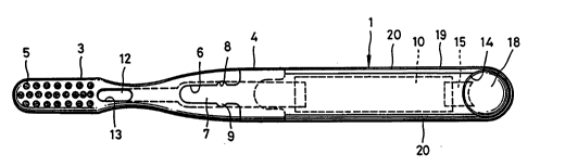
With reference first to Figs. 1 through 3,
there is shown an electronic toothbrush 1 which
includes a bristle portion 3 in which bristles
2 are implanted, and a handle 4 fitted detachably
into the bristle portion 3 to hold the same.
Preferably, the bristle portion 3 comprises
a molded body consisting of the synthetic resin
; or a combination of the synthetic resin and an
apatite-ceramic such as hydroxy apatite
[CalO(PO4)6( OH) 2] or apatite fluoride
[CalO(PO4)6F2]. The molded body of apatite-
ceramic is a mixture which includes ordinary
.`.b~
.~
'~'`''.,~''
.....
~ '
.:
"" '~,
-,;~: , ', ` ` ` ` :,
,'.''" , ' ' ` ' ' ' " '~' .
~ . ' ", ' ': ' ' '',:.,, " ' ` " ' '
. ' ~ ' ` ~ : : ~ ' ' '
.,,'. - , ' '~ ' .' ' :
' ';."
`',. ' . ~: , `
';':~ , .` :
2Q08640
- 6 -
. .,
1 synthetic resin (plastic) and 70 - 90 wt-~ of
. hydroxy apatite or apatite fluoride and is
obtained by applying about 500 - 700 kg/cm2 of
. pressure to the mixture at room temperature to
- i
-~ 5 mold the same.
~ .
.
,,:s
,,,, 10
':i
,~ .
,'.',
.,;.
. . .
,:,
....
:,.
",,.,,~
. :,~
` 20
"` .
.: .
.,:,
..~
~ 25
~,
: ., .
. ::. , . - . .:.. ; . ., . . :~ .-
- ~086~0
, - 7 -
1 The bristle portion 3 has a number of
holes 5 in which bristles 2 are implanted. The
holes 5 may be filled with hydroxy apatite or an
~; anti-fungus agent, before which the bristles 2
`~ 5 can be implanted,
The handle 4, which comprises a synthetic
resin or an ion-eluting ceramic, is formed to
have a longitudinally extending projection 7
capable of being fitted into a recess 6 formed in
the bristle portion 3.
The recess 6 is formed to have an engaging
groove 8, and the projection 7 is formed to have
an engaging protuberance 9 which mates with the
groove 8, thereby preventing the handle 4 from
~' readily detaching from the bristle portion 3.
As shown in Fig. 4, the handle 4 is formed
to include a recess 10 for receiving an electric
circuit, the recess being open to one side of the
handle 4. A plate-shaped first conductor 11 is
fixedly inserted into the projection 7 of the
handle 4. One end of the first conductor 11
projects into the recess 10, and its other end
protrudes from the projection 7. When the
protruding end portion of the first conductor 11
, is inserted into the bristle portion 3, it fits
.,
, into a slit 12 formed in the bristle portion.
A hole 13 is formed in the bristle portion
. . ~ ., .
. q
-~,
.. ;,; , ~ ~ ,
-~.: . . .
:;. .. . :', ~: .. ' ' '
:~ .
2008640
- 8 -
,'''
1 3 in the side thereof having the implanted
bristles 2. The distal end portion of the first
conductor 11 fitted into the slit 12 is exposed at
the hole 13 to improve conductivity. Through
the hole 13 has the form of an elongated slot in
the illustrated embodiment, it can be formed as
a plurality of apertures if desired.
The end of the handle 4 opposite the
projection 7 is formed to include a cavity 14 for
loading a battery cassette including the battery
, 18. A second conductor plate 15 is fixed in the
handle 4 in such a manner that one end thereof
' projects into the battery loading cavity 14 while
~'' the other end projects into the circuit accommo-
,? 15 dating recess 10.
' An electric circuit 17 of the kind shown,
:;" :,.
,~ for example, in Fig. 7 is formed on a circuit
board, to which a light-emitting diode 16 is
affixed in accordance with this embodiment. The
` 20 circuit board having this circuit is accommodated
in the recess 10. It should be noted that a
.,:,
sound-producing device instead of the light-
emitting diode 16 can be affixed to the circuit
~ board, in which case the electric circuit would be
:`` 25 designed to actuate the sound-producing device.
`;'j' After the battery cassette including the
~ battery 18 is loaded in the handle 4 accommodating
:, ...
~.....
:. :;
..
':;,'.
.. ~ ~ , . - .- ,
~ - 2008640
:
1 the circuit board, a cover 19 consisting of an
, electrically conductive material and formed to
. .
, serve as a second conductor is secured to the
. handle, thereby preventing the circuit board and
battery 18 from falling out. As shown in Fig. 5,
.:
the cover 19 is formed to have a generally C-
~ shaped cross section and includes longitudinally
Z extending side edges provided with longitudinal
' projections 20 so as to embrace the handle 4. The
-::
cover 19 is formed so that it can be fixedly
fitted onto the handle 4 from the end thereof
~' .
accommodating the battery 18. The cover 19
further has a tongue 21 fitted into a groove 22
provided in the handle 4, and is formed to include
a hole 23 positioned so that light emitted by the
light-emitting diode 16 on the circuit board
accommodated in the recess 10 can be seen from
the outside. The tongue 21 is formed to have a
hole 24 with which a fingernail is engaged when
detaching the cover 19.
As shown in Fig. 6, the loaded battery 18
. .
has a first (e.g., negative) electrode connected
to the conductor plate 15, and a second (e.g.,
positive) electrode connected to the cover 19,
which consists of the electrically conductive
material. The battery 18 is retained in the handle
4 so as not to fall out, though the retaining
:s-,~
"' .
:
::
:,.,.~
' :J,.`. ' ` ~' ' , ,
`'~'.,` ' ' ' ' , '' ~,. ' " . '
: i.'~" ' ' ' ' ' , : ' . " ' ' ,
,.,;:~,' ' . , :: ' ' ....... ..
.
2008640
-- 10 --
,:
I means is not shown.
When the electronic toothbrush is used,
the hand of the user contacts the cover 19 in
', grasping the handle 4, and the bristles 2 are
brought into contact with the teeth. As a result,
, a terminal on the hand side of the circuit shown
'~ in Fig. 7 and a terminal on the tooth side are
electrically closed, so that a current which passes
through the user's hand and body flows into the
surface of the teeth via the dental pulp tissue and
.~ tooth tissue proper. Calcium of fluorine ions
which elute out of the ion-eluting ceramic of the
~ bristle portion 3 collect on and permeate the
; teeth and tooth pulp. The flow of electric
~,
current causes the protein organic ions of
; plaque on the surfaces of the teeth to become
affixed to the toothbrush 1, so that the plaque
separates from the tooth surfaces.
;; When the electric current passes through
the interior of the toothbrush 1, a trigger
voltage is applied to the base of a transistor 26
(Fig. 7) by an amplifier circuit which includes
resistors Rl, R2 and an amplifier 25. The
" ..
trigger voltage causes the transistor 26 to turn
on, thereby activating the light-emitting diode 16,
which emits light as a result. The light from
` the light-emitting diode 16 can readily been seen
,.,.~ ,~
,',."~
.... .
;'
,~,,.: . . - - ` ~ ::
::`
2008640
:, , .
-- 11 --
,, :
1 from the outside through the hole 16.
' A preferred second embodiment of the
present invention will be described with reference
to Figs. 9 - 12 wherein an electronic toothbrush
, 5 1' lncludes a bristle portion 2', handle portion
3' detachable thereto and a battery cassette 4'
detachably secured to the handle portion 3'.
The head 6' of bristle portion 2' has a number of
holes 5' in which bristles are implanted. A plug
7' of electrical conductive material is fitted
into a hole near one of the holes 5'. The
bristle portion 2' is provided with a longitudinally
elongating central hole 8' so that a part of the
plug 7' will extend into the central hole 8',
which has a plate 9' of electrical conductive
material therein. The plate 9' is formed with at
least one step portion and opposed surfaces thereof
may be resiliently abutted on opposed walls of
:,
~ the hole 8' so as not to slip out from the
`'"' 20 central hole 8'. The central hole 8' is open
i ~
., .;
to a groove 10' wherein recesses 11, 12 are formed.
The plate 9' is provided at its one end with a
.: .~, .
~ flat wall 12'.
:~
The handle portion 3' has a recess 13'
being open to upper side thereof wherein an
electrical circuit 14', a first and second terminal
15', 16' are accommodated. A light-emitting
,~ ,.
., .,~
.
~ ~ `
2008640
: - 12 -
"~ .
;~, 1 diode and/or a sound producing device are affixed
to a circuit board on which the electrical circuit
~, is fonmed and negative terminal 19' and positive terminal
'. 20' are affixed. A vertical leg 21' of the first
terminal 15' is inserted into a slit 22 formed on
the recess 13 and a vertical leg 23' of the first
- terminal 15' is electrically connected to a
, positive electrode of a battery 24' so that the
....
:................. terminal 15' can be into contact with the positive
. 10 terminal 17'. The vertical leg 25' of the
second terminal 16' is inserted into a slit 26' of
: the handle portion 3' and a segment 27 is brought
into electrical contact with the negative electrode
of the battery 24'. The terminal 16' is abutted
. .
' 15 on the negative terminal 19' of the electrical
circuit 14'.
To close the top-opening of the recess 13',
a silicon seal 28 and an electrically conductive
cover 29 are secured to the handle portion 3'.
The cover 29 includes opposed walls which are
:.:. snap-fitted to the opposed outer surfaces of the
~ handle portion 3'. The projection 30' of the
. ~:,
handle portion 3' is press-fitted into a slit 30
of the cover 29.
The negtive terminal 18' of the electri-
~ cal circuit 14' is connected through a spring 31
`:.~.:~ to the cover 29 to make the negative side cover 29.
;^~,.
.... .
,~.: . - - - .
, ~ . : , . .
~ - , .. . .
.
: `- 2008640
: - 13 -
1 The seal 28 and the cover 29 are formed
to include holes 32, 33 so positioned that light
.s and/or sound emitted by diode and/or device
, 45, 46, 49, 50.
The handle portion 3' is provided at its
front portion with a hollow projection 34 in which
a stainless steel shaft 35 is inserted. The rear
- end of the shaft 35 comes into contact with the
positive terminal 20. The handle portion 3' is
provided with engaging protuberances 36, 37
. which mate with the grooves or slits 11, 12 of
the bristle portion 2'.
When the bristle portion 2' is attached
to the handle portion 3', the shaft 35 is inserted
into the hole 8' and the front portion of the
.-- handle portion 3' is also inserted into the
'. groove 10' of the bristle portion 2' so that the
`1' protuberances 36, 37 are snap-fitted into the
slits 11', 12', thereby firmly securing the
i 20 handle portion 3' to the bristle portion 2'.
When the bristle portion 2' is to be replaced
with a new one, the bristle portion 2' is drawn
sl ,
., in the direction apart from the handle portion 3'
.,, j .
.~ so as to easily separate each other.
The battery cassette 4' is provided at
.~' its front part with a T-shape recess 38 and a
. .j
~ stepped portion for disposing O ring 39. The
,:,
~ :
,
2008640
- 14 -
1 cassette 4' includes a stopper 40 and a tray 41
, of electrically insulating material having a
T-shaped part 42 which is placed in the recess 38.
~he front portion 43 of the cassette 4' can be
inserted into the rear opening of the handle
.':. portion 3' so that the positive electrode of the
battery 24' is brought into electrical contact
. with the leg 23' and the negative electrode thereof
: is in electrical contact with the leg 27'. The
. .:
:.~ 10 stopper 40 is engaged with a hole 44 of the
negative cover 29 so as to prevent the cassette
, 4' from sipping out of the handle portion 3'.
The electric circuits 14, for example, in
... Figs. 11 and 12 are formed on each circuit board,
~. lS respectively to which a light emitting diode 45,
.s~,, a buzzer 46, a composite sound source 49 for
',:3~ storing the desired music or voice, an amplifier
S0, or a speaker 51 together with resistors
Rl, R2, R3, an amplifier 47 and a transistor 48
are affixed.
:': When the electronic toothbrush i8 used,
~,, the hand of the user contacts the cover 29 in
~r~S
grasping the handle 4', and the bristles 2' are
brought into contact with the teeth 7'. As a
result, a terminal 29 on the hand side of the
circuit shown in Figs. 11 and 12 and a terminal
.~ 7' on the tooth side are electrically closed, so
:,..
.~';
.:: :, - -
' ~`' ~ ` . ' ' ,
'.' ' . ' '
`'., ' '~' ~ ' ~' ''' '
"' ~.......... ~
~ . ~
-,:., 20~s640
~ - 15 -
. .
1 that a current which passes through the user's
hand and body flows into the surface of the
, teeth via the dental pulp tissue and tooth tissue
,,
proper. The flow of electric current causes the
protein organic ions of plaque on the surfaces of
the teeth to become affixed to the toothbrush 1'.
so that the - plaque separates from the
tooth surfaces.
When the electric current passes through
the interior of the tooth brush 1'. a trigger
voltage is applied to the base of a transistor
48 (Fig. 11 or 12) by an amplifier circuit which
includes resistors Rl, R2, R3 and an amplifier 47.
The trigger voltage causes the transistor 48 to
turn on, thereby activating the light-emitting
diode 45, the buzzer 46 or the sound source 49,
. .;;
~ which emits signal as a result. The signal from
^.:
the such the device can readily been recognized
., ~:~.
`~ from the outside through the hole 33 or ear.
v~20 An embodiment illustrated in Fig. 13
relates to an improvement of toothbrush in Fig. 8.
A bristle portion 51 has bristles 52 implanted
, .~. .
~ therein. An electrically conductive conductor
- 53 is inserted into a longitudinal hole formed in
the bristle portion 51 and extends outwardly of
one end thereof. The other end of the conductor
:~
53 in the bristle portion 51 leads to the outside
.',:.;,
: - . ,
-
2008640
, .
- 16 -
:.
,~
1 through an electrically conductive plug 54. A
handle 55 is fitted detachably into the bristle
;-;
portion 51 so that the end portion of the conductor
;"~ 53 is brought into electrical contact with a
terminal 56 as supported in a hollow main body 57
.,
, made of a synthetic resin but has electrically
conductive plates 58 embedded on outer surfaces
of the main body 57. A cassette 59 is inserted
into the interior of the hollow main body 57
wherein a battery 60, a buzzer 61, a circuit
,;
~ ' board 62 having a circuit of Fig. 11 or 12. The
; parts 63 - 66 are assembled in each cavity of the
cassette 59 so as to electrically connect each
components to emit a light and/or produce a sound.
~-~ 15 The negative part of the circuit board 62 comes
."~", ...
~rrl into electrical contact with the plate 58 when
;, ,;,r;
~ the cassette 59 is inserted into the main body 55.
.~r.. , After insertion of the cassette 59 into the
:.,..;.:.
~ main body 55, both the members are bonded each
"~ 20 other so that the sealing effect to protect
~; electrical components from water is increased.
,,r~': When the electronic toothbrush in Fig. 13
is used, the hand of the user contacts the plates
58 in grasping the handle portion 55 and the
bristles 52 are brought into contact with the
teeth as well as the afore-mentioned embodiment.
As a result, the terminal 58 on the hand side and
. .,
~.,.
.
:~ .
., ~ . .:
.,~",. ~
. ' ' ' . ' ' ' ' ' . ' '
.. . . . . .
, , ~ .
2~08640
- 17 -
,,.
I the terminal 54 on the tooth side are electrically
closed to pass a current through the user's body
and separate sordes from the tooth surfaces.
When a music or voice from the sound
producing device or source is desired to be re-
placed, an embodiment illustrated in Figs. 14 and
15 is preferred wherein a cassette 67 is detachably
attached to a main body 57' of the handle portion
55'. The cassette 67 includes a buzzar 68 and
a melody board 69 which is put on a market. The
user will have different cassettes 67 including
different melody boards 69 and use a desired one
of them. One end of the cassette 67 are provided
'~:
'''r' with a pair of electrical terminals 70 which is
:,~
brought into electrical contact with terminals on
the circuit board like the circuit board 62 in
Fig. 13 and for the circuit diagram of Fig. 12
when the cassette 67 is inserted into the main
~ body 57' of the handle portion 55'.
,c 20 The present invention is not limited to
;~i the foregoing embodiments but can be modified in
-~ various ways based on the gist thereof without
~ departing from the scope of the claims.
.. ,.......................................................................... .
.,~,
,;:,
~ 25
~:,
-;`'"
. ..
,
. . . .
, ,^ , ,
.^. , ,