Note: Descriptions are shown in the official language in which they were submitted.
BACKGROU~ID O~ THE INVENTION
The in~ention relates to a method of heat treat-
mer,t of products advanced through a chamber by cir-
culating through the chamber hot, humid air that i8
exhaus~ed and supplied with humidity and heat and then
blown back -to the chamber, and an apparatus for use in
the method.
The method and the apparatus according -to the
invention are generally applicable and may thus for
instance be used for thawing out frozen products but
have primarily been developed and tested in connection
with the scalding of carcases, in parti ~ ar pig carcases,
and the invention will therefore be described in the
following particularly in connection with such applica-
tion.
It is ~nown in so-called suspension steam
scald ~ to scald pig carcases in a chamber by treatnEnt
with hot, humid air or air containing partlcles of
water. The pig car~ses are then scalded either by the con-
densation of the steam on the rind surface or by hot
particles of water from the circulating air.
NO patent No. 105 798 discloses an apparatus for
the treatment of carcases in a chamber with a vertical-
ly rising flow of steam by exhaustion of vapour from
the upper end and blowback of the steam to the lower
end. Humidity is suppliêd as vapour by means of an eva-
porator at the lower end of the chamber.
DK patent No. llS 190 deals with an apparatus
for thermally treating products, in particular for
scalding carcases, in which steam is applied to the
circulating air, followlng which it is guided past
refrigeration units causing the humidity of the air to
condensate as a fog of floating droplets. The products
are then thermally treated with a fog of hot particles
of water. The apparatus is extremely energy consuming
because large amounts of heat get lost through the
refrigeration units.
.
'. .
In another practised apparatus ~he consumption
of vapour is reduced by replacing the refrigeration
units by heating units which together with the supply
of aqueous vapour maintain a well defined temperature
and humidity of the air in a chamber, e.g. 85 to 90% of
relative humidity. The contro:L of the heating units and
the supply of vapour are effected by ~eans of a humi-
dity sensor and a temperature detector, but at varying
loads of the chamber it has turned out to be difficult
to obtain satisfactory joint control of temperature and
humidity. An example of a process utilizing such an
apparatus is disclosed in DK patent application No.
5006/84 dealing with a method of scalding carcases by
directing a hot, humid jet of air ha~ing a relative
humidity of no less than about 80% and a temperature of
about 62C towards every part of the suspended car-
cases.
DK patent application No. 1643~85~relates to an
apparatus for scalding suspended carcases in which heat
and humidity are imparted to the circulating air by
means of a combination of water atomizers and burners
discharging directly in the duct for blowback of the
circulating air to the chamber. A problem involved by
this method is the presence of exhaust gas in the
treatment air.
With a view to thawing out frozen products use
is nowadays made of chambers with injection of hot air
with controlled humidity.
In this respect the control of temperature and
time according to a fixed program for the actual pro-
duct is generally practised. It is very important that
the temperature is controlled very strictly and that
the air humidity is ~ept above a determined level,
since too dry air, e.g. when thawing out frozen pro-
ducts, causes such products to become dry on their sur-
face, thereby lowering their quality and value, and
since a too quick thawing ~ut implies a too heavy loss
of drippage, following which 1:he products also decline.
A general problem of the known methods and
apparatuses is unstableness at fluctuating loads and
other heat/cold stresses from outside, thereby ham-
pering an exact, controlled heat treatment.
It is the object of the present invention to
provide an inexpensive and effective method of heat
treatment capable of eliminating unstableness as
regards temperature and humidity at varying load or
other heat/cold stresses.
SUMMARY OF THE INVENTION
It has now turned out that the purpose according
to the invention is obtained by a method characterized
in that heat and humidity are supplied to the air by
atomizing excess water into the circulating air, in
relation to saturation thereof with steam, at a tem-
perature higher than that desired in the chamber.
This method provides for obtaining a very stable
heat treatment because it inherently neutralizes
fluctuations. If the temperature for instance falls in
the chamber, for instance due to increasing load, a
smaller quantity of water will simply evaporate from
the surface of the water particles that are atomized
into the flow of air, thereby requiring a smaller
amount of heat to be bound as heat of evaporation,
thereby counteracting the drop of temperature. If the
temperature in the chamber rises, correspondingly more
water will be evaporated from the particles of water
and atomized into the circulating air, and a larger
amount of heat will be bound as heat of evaporation,
thereby preventing the temperature from increasing. A
very quick re-adjustment to the desired processing
parameters is thus obtained.
As it appears from the above it is completely
decisive of the method concerned that a sufficiently
large surface area of the water particles be provided
in order to obtain an effective transition of H20 from
the liquid phase to the gas phase.
The method according l:o the invention is very
economical as regards energy and entails the additional
advantage that energy is only consumed in the on-load
condition of the chamber, since water is not condensed
in the chamber when unloaded and, therefore, the ato-
mized water will not evaporate but may merely be recir-
culated. Moreover, the method is very flexible asregards the heat source for heating water to a higher
temperature than desired in the chamber. For heating
purposes, use may thus be made of waste heat from
anywhere in the slaughterhouse. In this respect lt
should be observed that in a slaughterhouse hot water
at a temperature of about 82C is generally available.
The method according to the invention is,
moreover, economical as regards water consumption as
an expected consumption of water per pig carcases is about 3
to 6 liters or even dcwn to ~ liter.
The effective, stable method according to the
invention makes it possible to eliminate the problems
of red-colouring the neck and head regions of the
pig caracases that might occur by the prior methods of suspen-
sion scalding which is due to insufficient effective-
ness.
Advantageously, the temperature of the water is
regulated by means of a controllable heat source, and
the excess of atomized water is recirculated.
After the above atomization an atomization of
water of a lower temperature is advantageously effected
into the circulating air in order to ensure a substant-
ially complete saturation of the circulating air with
steam.
In the method according to the invention it may
be advantageous to supply dry heat to the circulating
A
I
air by means of a heat source prlor to said atomization
of water of a temperature h:Lgher than that desired in
the chamber, in particular at: the beginning of the pro-
cess to obtain a quick adjustment to the desired pro-
cess parameters.
As mentioned above, the method according to theinvention is of essentia~ interest in connection with
the scalding of carcases and is particularly advantage-
ous in the so-called "suspension scalding" of pig c~x~ses.
In that respect the air is kept at a temperature in the
range between 60 and ~5C and a relative humidity of at
least 90%.
It may be advantageous to vary the temperature
and~or humidity throughout the chamber to obtain the
optimum heat treatment. This is expediently obtained by
independent and individual control of the temperature
in sections throughout the chamber by treating the air
as outlined above in a number of separate air circula-
tion circuits.
The invention also relates to an apparatus for
heat treatment of products advanced through a chamber,
comprising one or more subunits, through which the pro-
ducts to be subjected to heat treatment are passed, and
a fan which on its draught side is connected with the
subunit for exhaustion of the humid air from the
chamber, and on its delivery side with a flow passage
for blowback of the humidified air to the subunit, and
characterized in that it includes a water atomizer for
water of a higher temperature than that desired in the
chamber, and a heat source for heating the water to be
supplied to the water atomizer.
Said heat source may in an embodiment of the
apparatus according to the invention be a heat
exchanger with controlled supply of heat medium, pre-
ferably by means of a control device. The above men-
tioned water atomizer discharges advantageously in the
flow passage.
A
In an embodiment of the apparatus according to
the invention a further atomizer for water having a
lower temperature may be positioned after the first
mentioned atomizer. A heat source for the supply of dry
heat may be positioned before the first mentioned atom-
izer, said heat source being advantageously according
to an embodiment a heat e~changer with controlled
supply of heat medium, preferably by means of a control
device allowing the admission of heat medium at a
considerable thermal deficit in the circulating air.
A preferred embodiment of the apparatus
according to the invention is characterized in that a
basin is arranged below the water atomizer or each
water atomizer in the flow passage, each basin being
connected with the corresponding water atomizer.
According to this embodiment the non-evaporated
water, atomized into the circulating air, is collected
in the basin from which it may easily be recirculated
to the water atomizers. This provides for obtaining a
good water and energy economy.
The heat source for heating the water recir-
culated to the water atomizer to a desired temperature
is according to an additional embodiment of the appara-
tus according to the invention disposed in or in asso-
ciation with the basin below said water atomizer.
Preferably, the flow passage on the deliveryside is connected with the subunit according to prior
art through a series of tubes provided with openings
uniformly distributed over the wall of the subunit.
chamber. Such an arrangement provides for obtaining an
effective distribution of the humid air injected into
the subunit, and the rind surface is scalded at a
constant air velocity substantially all over the-entire
surface of the carcase.
In order to vary the temperature and~or humidity
throughout the chamber, thereby obtaining a high flex-
h
3~
ibility and improved control with a view to the heat
treatment of the products in the chamber the apparatus
according to the invention may, as mentioned above,
comprise a series of sections or subunits corresponding
to apparatuses as stated in the preceding, and in
mutual alignment. Each of said sections may have a
separate air circulation system for the supply of heat
and humidity to the circulating air so that the tem-
perature and/or air humidity may be controlled indivi-
0 dually in each of the sections of the apparatus.BRIEF DESCRIPTION OF THE DRAWINGS
Fig. 1 is a schematical, cross-sectional view of
an apparatus according to the invention,
Fig. 2 is a section of a first subunit in the
same apparatus according to the invention along the
line A-A in Fig. 1,
Fig. 3 illustrates a section of a last subunit
in the same apparatus according to the invention along
the line A-B in Fig. 1,
Fig. 4 is another embodiment of the section as
shown in Fig. 2, and
Fig. 5 is a schematical cross-sectional view of
an apparatus according to the invention as shown in
Fig. 1, but with another arrangement of holes for
distributing hot and humidified air.
DETAILED DESCRIPTION OF THE PREFERRED EMBODIMENTS .
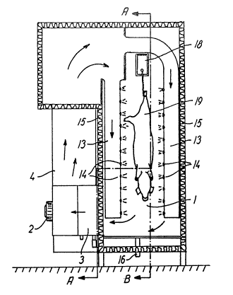
In Fig. 1 a scalding chamber (or a subunit
thereof) is designated 1 in which the carcases are
subjected to treatment. At the bottom the chamber is
provided with an outlet 16 for condensed water. The
air is passed from chamber 1 through a heat exchanger
3 to the draught side of a fan 2 connected on the
delivery side with two successive -air humidifiers.
After the air has been heated and humidified therein it
flows out into a duct. The flow passage formed by the
humidifiers and the duct is designated 4. From the
z~
duct the air is again in~ected into the chamber
through hollow tubes 13 provided with a series of
holes or nozzles 14 for distributing the hot and
humidified air, said holes or nozzles being positioned
upwards the insulated chamber wall 15.
A conveyor 18 for the suspension and con-
tinuous conveyance of the carcases 19 is positioned
at the top of chamber 1.
Fig. 2 illustrates the part of the air cir-
culation circuit through which humidity and heat aresupplied to the air.
The first air humidifier accommodates a water
atomizer 5. Said atomizer may be of any arbitrary type
ma~ing provision for a sufficiently good atomization to
obtain the desired area of water film on the water par-
ticles. An additional atomizer 6 is accommodated in
the second air humidifier. Basins 10 and lOa for
collecting the part of the water that is atomized into
duct 4 but does not evaporate, are located under each
of atomizers 5 and 6. Basins 10 and lOa supply
water to their respective atomizer through pumps 11
and lla. In basin 10 the water is kept heated by
means of a heat source 7. Heat source 7 may be of an
arbitrary, appropriate heat source, such as a heat
exchanger capable of utilizing, as the heat medium,
excess water from other processing steps in the
slaughterhouse.
A temperature detector 8 is positioned at the
exhaust outlet 20 and immediately before heat ex-
changer 3. It is connected with a control device 9controlling the supply of heat medium to heat exchanger
~ and supplying supplementary heat to basin 10 upon
fall of the air temperature.
The two basins 10 and lOa are in communica-
tion through a valve 12 that is opened by means of alevel sensor 17 in basin 10, and still a level sen-
sor 17a is arranged in ves;sel lOa for the supplyof supplementary water.
The hot water for atomizer 5 may also be com-
pletely or partially supplied directly from outside and
may for instance be obtained by means of excess heat
from other processing steps in the slaughterhouse.
Control device 9 also controls the supply of
heat medium to heat exchanger 3, however, preferably
so that heat medium is only admitted when heat source
7 in itself is not capable of covering the need for
heat for a shorter time. Thus, heat exchanger 3
begins particularly to function upon starting the plant
and when subjected to constantly heavy load by car-
cases, and is supplementing source 7.
The heat medium in heat exchanger 3 is advant-
ageously vapour but may as well be any other suitable
medium.
The shell side of heat exchanger 3 may be in
connection with basin lOa so that the used heat
medium, in this case vapour, may be supplied by means
of level sensor 17a to basin lOa as supplementary
water.
In respect of providing a uniform air flow a
diffusor shown in dashed lines in Fig. 2 may be
arranged at the air inlet of the first humidifer. A set
of baffles may further be positioned at the air outlet
of the second humidifier, likewise as shown.
The apparatus includes sluices 21 for feeding
the carcases into chamber 1 and for discharging them,
of the type having two sets of "doors" made from a
rubber material and arranged in mutual alignment. Said
doors are pushed open by the gravitational force of the
carcases.
Fig. 3 illustrates the distance between the
porkers continuously conveyed through chamber 1.
The tubes 13 for the humidified air are
uniformly spaced apart throughout chamber 1.
Nozzles 14 may be disposed adjustably so that
the por~ers are treated with~ a uniform air flow all
over their surface.
Fig. 4 illustrates a preferred embodiment of the
part of the air circulation c:Lrcuit through which humi-
dity and heat are supplied to the air.
The air humidifier accommodates a water atomizer
of a type as mentioned above in connection with Fig.
2. Basin 10 for collecting the part of the water that
is atomized into duct 4 but does not evaporate is
located under atomizer 5. Basin 10 supplies water
through pump 11 and further through the tube side of
heat exchanger 7 to water atomizer 5, said water
supplied to water atomizer 5 being heated by means of
an appropriately heated liquid supplied to the shell
side of heat exchanger 7. Preferably said
appropriately heated liquid is excess water from other
processing steps in the slaughterhouse.
A temperature detector 8 is positioned at the
exhaust outlet 20. It is connected with a control
device 9 controlling the supply of heat medium to the
shell side of heat exchanger 7 and supplying supple-
mentary heat to the water atomizer 5 upon fall of the
air temperature.
A level sensor 17a is arranged in basin 10
for the supply of supplementary water.
The apparatus includes sluices 21 as mentioned
in connection with Fig. 2.
Fig. 5 is a variant of the apparatus according to
the invention illustrated in Fig. 1, in which the
guiding of tubes 13 is so that part of the holes or
nozzles 14 will flow the heated and humidified air
from below and upwards against the suspending carcases.
The chamber may be composed of subunits and the
length of the chamber may thus be varied arbitrarily by
choice of a suitable number of subunits. The capacity
of the chamber may thus be var1ed. One subunit may
comprise an air circulation circuit for the exhaustion
of air from the subunit, supply of humidity and heat to
the air and blowback thereof to the subunit. The
apparatus may thus consist of a series of such subunits
in mutual alignment, following which the temperature
and humidity may be controlled separately in the indi-
vidual subunits.
This is particularly desirable with respect to
the suspension scalding of pig carcases, a higher temper-
ature at the beginning of the chamber causing the rind
surface to be rapidly heated to the desired temperature
which is then upheld during conveyance through the
chamber.
The invention will now be further elucldated by
by means of non-limiting examples.
EXAMPLE 1
In this example reference is made to Figs 1 to 3
of the drawings.
Stuck porkers i.e. pig carcases 19 are after bleeding passed
into chamber 1 by conveyor 18. The carcases are con-
veyed through chamber 1 at a velocity regulated so as
to obtain a stay of time for 4 to 9 minutes, preferably
5 to 7 minutes, in dependence on the temperature in the
chamber. During the stay within chamber 1 the car-
cases 19 are treated with the humidified in~ected
air, following which they leave the chamber, and the
bristles are easily torn out in a following dehairing
machine.
During the stay in the chamber the humid air is
exhausted from chamber 1 through exhaustion outlet
20 and the temperature thereof i5 detected by ueans of
temperature detector 8. The air i8 passed through heat
exchanger 3 supplying dry heat thereto, if necessary,
during starting, peak load periods or in similar situa-
tions in which the heat source ~ is not capable of
A
. .
2~
12
generating the required amount of heat to rapidly
obtain the intended working temperature of the cir-
culation air. In said cases control device 9 turns on
heat medium and regulates the amount of heat medium
supplied to heat exchanger 3. The air is exhausted
further through fan 2 and is in~ected into the first
humidifier in which excess water of a higher temper-
ature than that intended in chamber 1 is atomized by
means of water atomizer 5, thereby obtaining a good
contact between the water droplet surface of the in-
jected particles and the circulating air. The air is
thereby humidified by evaporation of water from the
water droplet surface. The evaporated quantity of water
depends on the temperature of the air and on the tem-
perature of the water and on the contact between the
air and the water droplet surface, including the total
area of surface of the droplets. The circulating air
further receives heat from the hot water atomized into
the air.
In the second humidifier water of a lower tem-
perature i5 subsequently atomized into the circulating
air through water atomizer 6, thereby ensuring sub-
stantially complete saturation of the air with aqueous
vapour.
The non-evaporated portion of the atomized water
is collected in basins 10 and lOa from which it is
fed back directly to water atomizer 6 for atomization
and to water atomizer 5, respectively, after heating
by means of heat source 7. The temperature of the
water in basin 10 and thus of the water in atomizer
is regulated by controlling the supply of heat
medium to heat source 7 by means of control device 9.
Temperature detector 8 transmits a measuring signal
to control device 9 which opens for the supply in
dependence on the difference between intended and
detected temperature of the air. Supplementary water is
supplled to basin lOa as a compensation for the eva-
porated water. The amount of supplementary water is
controlled by means of level sensor 17a. Supplementary
w~tor to ba~ln ~o 1~ nuppllod rrom basln lOa by
means of valve 12 controlled by level sensor 1~.
The hot air thus humidified is in~ected into
chamber 1. Upon contact with the colder pig carcases 19
water will condense on the surface thereof, thereby
effecting a heating of the rind surface. The heating of
the rind surface depends on the temperature and humi-
dity of the treating air and on the contact between the
injected air and the rind surface.
The chamber temperature is kept at a value in
the range from 60 to 75C, preferably from 61 to 67C.
16 It depends on the time of treatment so that a shorter
time of treatment necessitates a higher temperature.
After starting and upon adjustment to the
desired process parameters during the supply of dry
heat by means of heat exchanger 3 and during the
supply of heat by means of the hot water atomized into
the circulating air by atomizer 5, the necessary heat
may under normal operating conditions be supplied to
the air solely from the atomized hot water.
Pig carcases scalded in this manner have turned out
to possess a very fine rind quality without red-colour-
ing of the neck and head regions.
EXAMPLE 2
This example illustrates a preferred embodiment
of the invention wherein pig carcases are scalded according
to the invention in an apparatus according to the in-
vention comprising two consecutive chambers or subunits
each including an air circulating circuit as illus-
trated in Fig. 4.
Stuck porkers i.e. pig carcases 19 are after bleeding passed into ,~
first chamber 1 by conveyor 18. Said porkers are
conveyed through chambers 1 at a velocity regulated
A
to as to obtain a stay of t:lme for 6~ minutes. During
the stay within chambers 1 the pig carcases l9 are
treated with humidified in~ected air, following which
they leave second chamber 1, and the bristles are
easily torn out in a following deharing machine.
During the stay in each chamber the humid air is
exhausted from chamber 1 through exhaustion outlet
and the temperature thereof is detected of means of
temperature detector 8. The air is exhausted further
through fan 2 and is injected into the humidifier in
which excess water of a higher temperature than that
intended in chamber 1 is atomized by means of water
atomizer 5, thereby obtaining a good contact between
the water droplet surface of the injected particles and
the circulating air. The air is thereby humidified by
evaporation of water from the water droplet surface.
The evaporated quantity of water depends on the tem-
perature of the air and of the temperature of the water
and on the contact between the air and the water
droplet surface, including the total surface of the
droplets. The circulating air further receives heat
from the hot water atomized into the air.
The non-evaporated portion of the atomized water
is collected in basin 10 from which it by means of
pump 11 is let through the tube side of heat
exchanger 10 to water atomizer 5. The temperature
of the water in atomizer 5 is regulated by
controlling the supply of heated liquid to the shell
side of heat exchanger 7 by means of control device
9. Temperature detector 8 transmits a measuring sig-
nal to control device 9 which opens for said supply
in dependence on the difference between the intended
and detected temperature of the air. Supplementary
water is supplied to basin 10 as a compensation for
the evaporated water, controlled by means of level sen-
sor l~a.
A
. ,
The hot air thus humidlfied is injected into
chamber 1. Upon contact wit:h the colder pig caracases 19
water condenses on the surface thereof, thereby
effecting a heating of the rind surface. The heating of
the rind surface depends on the temperature and humi-
dity of the treating air on the contact between the
injected air and the rind surface.
At an average load of the apparat~ according to
the invention by 200 pig caracases per hour it is possible to
maintain a substantially constant temperature of 62C
in the chamber, the air velocity in the duct amounting
to 6 to 7 m/sec. This temperature does not fluctuate
more than 0.5C when changing from idling to full load
of the chamber by porkers. The temperature of the
injected water varies at the same time between 67 to
77C in dependence on the load variations. The relative
humidity in the chamber amounted to 100% according to
measurements by wet and dry thermometer. 3000 litres of
water were atomized per hour, the consumption of
supplementary water amounted to 100 litres per hour and
as the heating liquid for the shell side o~ heat
exchanger 7 slaughterhouse waste water at a tem-
perature of about 82C was used.
Pig carcases scalded in this manner possess a very
fine rind quality without red-colouring of the neck an~
head regions.