Note: Descriptions are shown in the official language in which they were submitted.
, .J 5 ~3
~1--
SUTURING APPARATUS
Backqrou_d_of the Invention
The present invention relates to suturing and more particularly
to a novel apparatus for applying a suture to close a wound or
incision.
At the present time it is the general practice to apply sutures
with the aid of a hand held needle. Occasions may arise when it
is difficult to force the needle ~hrough the tissue at the
opposite sides of the wound or incision to be closed.
Furthermore, when handling the needle, particularly in difficult
situations, there is a risk that the doctor may be punctured by
the needle. Such an accident would, of course, subject the
doctor to the risk of infection.
In an effort to overcome the disadvantages of using the hand held
needle, a power-driven suturing apparatus has been suggested as
disclosed in U.S. patent No~ 4,557,265. The present inventio~
___ . _
5~
-2-
contemplates further advantages and improvements over this prior
apparatus.
Sum~ry o~ ~he Inven~ion
It is an important ob~ect o~ the present invention to provide a
novel power-driven suturing apparatus constructsd so that
movement of a needle can be controlled easily and accurately.
It is a further ob~ect of the present invention to provide a
novel apparatus for suturing of the above described type which is
constructed so that the needle and parts of the apparatus
directly assoaiated with the needle are disposable so as to
reduce any possibility of lnfection.
A more specific ob~ect o~ the present invention is to provide a
novel suturing apparatus o~ the above described type including a
handle unit which may contain a motor, a head unit for a needle
and quicX-disconnect means between the two units for enabling the
head unit to be readily removed and replaced.
Another ob;ect of the presen~ invention is to provide a novel
suturing apparatus o~ the above described type which may be
relatively easily and economically manufactured.
In carrying out the invention it is contemplated that the novel
apparatus will include a handle preferably housing a motor having
an output drive sha~t and a head assembly or unit with a
quick-disconnect connection to the handle and drive shaft, which
head assembly compri6es a housing, a plurality of drive rollers
constructed and arranged ~or supporting and driving the needle in
a precisely controlled manner around a circular path o~ travel,
and gear means operatively connectable with the drive shaft for
driving the rollers.
?759
--3--
Bxie~_~esc~iptions o~_th~_~rawinas
Other ob~ects o~ the present invention will become apparent from
the following description and the accompanying drawings wherein:
Fig. 1 is a slde elevational view, partiaily broken away, showing
an apparatus for suturing incorporating ~eatures o~ the present
invention;
Fig. 2 is an end elevational view of the apparatus as seen from
the right hand end o~ Fig. l;
Fig. 3 is an enlarged fragmentary sectional view taken along line
3-3 in Flg. 1;
Fig. 4 is an end view of the roller assembly shown in Fig. 3;
Fig. 5 is a side elevational view o~ a main housing member of the
head assembly included in the apparatus o~ Fig. 1;
Fig. 6 is an edge view o~ the housing member as seen from the
right hand side of Fig. 5;
Fig. 7 is a side elevational view o~ the ~ig. 5 housing member as
seen from the opposite side:
Fig. 8 is a side elevational view of a second housing member o~
the head assembly;
Fig. 9 is an edge view of the Fig. 8 housing member as seen from
the right hand side of ~ig. 8;
Fig. 10 is a side elevational view o~ a third housing member o~
the head assembly o~ Fig. 1; and
Fig. 11 is an edge view o~ the Fig. 10 housing member as seen
from the left hand side o~ Fig~ 10;
Z~ 5~9
-4-
De~ai~ed_Descr ~ ~ a Preferred Embodiment
Referring now to the drawings wherein like parts are designated
by the same re~erence numexals throughout the various figures, an
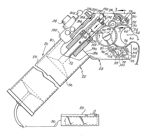
apparatus 20 incorporating features of the present invention is
shown in Figs. 1 and 2. The suturing apparatus 20 comprises a
handle unit 22 and a head unit or assembly 24 described in detail
below.
The handle unit 22, in the embodiment shown, includes an
elongated tubular case 25 o~ a siz~ and shape such ~hat it may be
easily held in the hand of an operator. A motor 26 of any
sui~able known construction i~ mounted within the casing or
handle 22. Preferably, the motor is a reversible electric motor
connectable to any suitable source o~ power. In the embodiment
shown, a battery pack 28, also o~ known construction, is
connected to the motor 26 by wires 30. The motor 26 has an
output or drive shaft 32 extending axially out o~ the casing for
connection with the head assembly in the manner described below.
The handle unit also includes means for controlling the operation
of the motor. Preferably the control circuitry has a flrst
push-button switch 34 located on the casing ad~acent to the head
assembly and adapted to be pressed or actuated to energize the
motor to drive the needle continuously as will be hereinafter
described. In addition, puæh-button switches 36 and 38 are
mounted on the casing at opposite sides thereof às shown in Fig.
2 for enabling the oper~tor to ~og the motor selectively in
forward and reverse directions respectively. A printed circuit
board 40 or o~her suitable means containing circui~ components o~
conventional design is mounted in the casing and connected
between the motor 26 and the switches 34, 36 and 38 for enabling
the operator to control ~he motor in the manner described.
-5~ 9
The head assembly 24 comprises first, second and third housing
members 42, 44 and 46 respectively shown in detail in Figs. 5-7,
8, 9 and 10, 11. ~he housing members, when assembled as shown ln
Figs. 1 and 2 provide a housing adapted to contain mèans
generally designated by the numeral 48 ~or guidlng and driving an
arcuate needle 50 around a circular path of travel 52 in the
manner to be described. The needle 50 has a pointed forward or
leading end 54 and a trailing end 56 with an eye or the like
adapted to be connected with a suture thread 58. It i8 noted
that the needle extends in a circle for about 270 degrees and
there is a gap 60 between the opposite ends of the needle to
enable edges 62 and 64 of tissue to be positioned in the gap for
suturing in the manner to be desc~ibed.
The needle guidl~g and driving means 48 comprises roller
asRemblies 66, 68, 70 and 72 spaced around and de~ining the outer
edge o~ the needle path o~ travel 52. The roller assemblies 66
through 72 are identical, so that only the assembly 66, which is
shown in detail in Figs. 3 and 4 need be specifically described.
The roller assembly 66 includes a shaft 74. An annular drive
roller segment 76 is integrally formed with a central portion of
the shaft for cooperating with an opposing drive roller segment
78. The drive roller segment6 combine to derine a generally
V-shaped groove 80 and present opposing inclined or diversing
surfaces 82 and 84 for frictionally engaging opposite side
portions of the needle for driving the needle. The roller
segment 78 is mounted on the shaft 74 with a slip fit so that it
is free to move axially o~ the shart. Resilient or spring means
in the form of a rubber washer 86 is disposed between the roller
segment 78 and a ~top or bacX-up washer 88, which is press-fitted
on and non-rotatable relative to the shaft. The dimensions are
such that the rubber or spring washer resiliently biases the
roller segment 78 for pinching the needle between the surfaces 82
and 84. While the roller segment 78 is axially slidable on the
shaft, it is e~fectively rotatably driven by the shaft through
the friction coupling provided by the rubber washer 86 and the
?759
-6-
back-up washer 88. With the structure just described, the roller
is sffective for aggressively gripping and frictionally engaging
opposite portions o~ the needle ~or ensuring acourate and
controlled movement of the needle in response to rotation o~ the
xoller. A g~ar 90 i8 ~ixed on the shaft 74 by means o~ a ~orce
~it or other suitable device such as key, which gear is adapted
to be driven in 'he manner to be described for driving the roller
assembly.
As shown in Figs. 1, 5, 6 and 7, the first or main housing member
42 of the head assembly is ~ormed with a transverse aperture 92
for receiving the shaft 74 of the roller assembly 66. This head
member is provided with additional similar transverse apertures
94, 96 and 98 ~or accommodating shafts 100, 102 and 104 of the
roller assemblies 68, 70 and 72. As previously indicated, the
roller assemblies 66 through 72 are positioned ~or engaging the
needle and de~ining the outer margins of the circular path 52.
In addition it is to be noted that the roller assemblies are
located and spaced from each other ln a manner such that at least
three o~ the rollers are always in suppoxting and driving
engagement with the needle during passage of the point of the
needle into and substantially entirely through the tissue being
sutured. It is noted that the groove 106 is ~ormed in the wall
o~ the housing number 42 as shown in Fig. 7 to provide clearance
for thP needle moving around from the path 52. The groove is
positioned so that its outer peripheral wall or surface is
located radially outwardly of the po~nts of contact between the
roller assemblies and the needle, so as to minimize or avoid any
frictional contact between the needle and the wail of the
groove.
The drive mean~ for the roller assemblies includes not only the
gear 90 on the shaft 74, but corresponding gears 108, 110 and 112
on roller shafts 100, 102 and 104 respectively. In addition, an
idler gear 114 mounted on shaft 116 meshes with gears 90 and 108
and another idler gear 118 mounted on shaft 120 me~hes with gears
.
110 and 112. A main drive gear 122 mounted on shaft 124 meshes
with gears 108 and 110 so that all of the roller assemblies will
be precisely driven in unison. The drive gear l22 also meshes
wi~h and is driven by a worm gear 126, which is located in a bore
128 formed in the housing member 42. A roller bearing 130 is
radially supported on shoulders 132 at an inner end o~ the bore
for a purpose to be descri~ed. A thrust bearing 135 is provided
in the opposite end of the bore for absorbing the end thrust from
the worm gear when the gear is driven in the direction of the
arrow ~see Fig. 1) for advancing the needle.
Referring again to Figs. 5-7, it is seen that the housing member
42 has apertures 134 and 136 respectively for receiving the
shafts 116 and 120 o~ the idler gears and another aperture 138
for receiving the shaft 124 o~ the drive gear 122, disposed in a
pocket 140.
Referring particularly to Figs. 8 through 11 along with Figs.
5-7, it is seen that t~e housing members 44 and 46 complement the
maln housing membar 42 so as to provide a complete housing into
which the roller assemblies and drive gearing may be readily
assembled. Thus housing member 44 is provided with shaft
accommodating apertures 142, 144, 146 and 148, adapted to be
aligned with the apertures 92, 94, 96 and 98 for receiving ends
of the roller assembly sha~t. Additional apertures 150 and ~52
in the housing member 44 align with the previously described
apertures 134 and 136 ~or receiving ends o~ the idler gear shaft
and aperture 154 aligns with the aperture 138 for receiving an
end at the main drive gear sha~t.
The supplemental or third housing member 46 is also formed with
apertures adapted to receive ends of the various roller and gear
shafts projecting from the main housing member. Thus housing
member 46 i8 ~ormed with apertures 15Ç, 158, 160 and 162 adapted
to align with the roller sha~t apertures 92, 94, 96 and 98 and
the main housing member~ Additional apertures 164 and 166 in the
.,,....,:: :.
X6~ 759
-8-
housing member 46 align with the idler gear shaft apertures 134
and 136 in the main housing member and aperture 168 in the
housing member 46 aligns with the main gear drive sha~t aperture
138 in the housing member 42.
The housing member 46 has a side surface or face 170 adapted to
abut and mate with a side sur~ace 172 on the main housing member
42. As a result, the housing member 46 will cover tha groove 106
formed in the main housing member. As shown best in Fig. 9, the
housing member 46 includes an arcuate flange 174 projecting from
the face 170 for entering the groove 106 and thus closing the
inner side of the circular path o~ travel 52 of the needle.
While the flange 174 cooperates with the surfaces of the groove
106 to enclose the needle path of travel, it is contemplated that
the needle will be primarily supported as well as driven by the
rollers whereby the needle will avoid substantial frictional
contact with the s~ationary sur~aces of the housing members which
might interfere with the smooth operation of the needle.
Again referring to Figs. 5-11, it is seen that the housing
members 42 and 44 have complementary beveled sur~aces 176 and
178, while the opposite side housing member 46 has a
corresponding surrace 180 so that ~he overall combination
provides the housing or head structure with a tapered edge
adjacent to the location where the sutures are to be applied so
as to enhance the ability of the doctor to see the exact manner
in which the needle is being inserted to suture a wound.
In accordance with a feature the present invention, the head unit
or assembly i8 adapted to be easily and quickly connected and/or
disconnected from the handl~ unit. More speci~ically, the handle
unit has an enlargement or fitting 182 at one end of the case 25,
which fitting carries the p~eviously-desoribed switches 34, 36
and 38. In addition, the ~itting 182 presents a flat
longitudinal sur~ace 184 and a Plat transverse surface 186
adapted to mate with and engage complementary flat surfaces 188
,; ,, ,.. ,,,,, ~ ..... .......................... ....
-9~
and 190 presented by the main housing member 42. These mating
surfaces ef~ectively lock the handle unit and the head assembly
against relative rotation when the parts are in relationship as
shown in Figs. 1 and 2.
As shown in Fig. 1, drive sha~t 32 extends from the case 25 and
parallel to the surrace 184 ~or entry into a complemen~ary bore
192 in the worm gear 126. The drive shaft 32 includes a
non-circular portion pre~erably having ~lat surfaces 194 adapted
to engage complementary ~lat sur~aces 196 ~ormed in the wall of
the worm-gear bore for providing a driving connection between the
shaft 32 and the worm gear. At the outer or free end of the
sha~t 32 a reduced diameter section 19~ is provided for entry
into and support by the radial ball bearing 130. While the
bearing 130 provides lateral or radial support for the drive
shaft and worm gsar, the thrust bearing 135 is adapted to
accommodate the axial thruæt generated by the worm gear when the
apparatus is actuated ~or driving a needle into the tissue to be
sutured.
It will be apprec~at~d that the head assembly can be quickly and
easily assembled with the handle unit simply by slipping the worm
gear over the outer end of the drive sha~t 32 until the housing
sur~ace 190 engages the surface 186. Preferably a spring-biaRed
ball detent 200 tsee Fig. 1) i8 provided between the fitting 182
and the housing member 42 for releasably retaining the head
assembly.
While the operation o~ the suturing apparatus is apparent from
the previous description, a brief summary is as follows. In the
first instance a new and sterile head assembly is to be engaged
with the handle unit. Then, in the embodiment shown, the battery
pack should be switched on. I~ desired, an indicator light 202
may be provided on the fitting 182 to show when the battery pack
is on. Then when the do tor wishes to advance the needle, it is
merely necessary to pr~ss the switch 34 for continuous operation
-10- ;~C~?'-~59
or the switch 38 ~or intermittent or ~ogging operation. When
either one of these switches axe energlzed, the drive sha~t 32
drives the worm gear which in turn driv~s the gear 122 and the
roller and idler gears in the directions of the arrows in Fig. 1.
The combination o~ the worm gear and drive gear 122 provides ~or
des~red high speed reduction so that the needle may be driven at
a pace acceptable to the doctor~s needs. In addition, the drive
gearing, including the worm gear, is self-locking so that
whenever the motor is de-energized, the gearing cannot move and
the needl~ will be securely held in a fixed position. In the
event it is desired to retract the needle, it is merely necessary
for the doctor to depress the reverse switch 38.
It is contemplated that the housing members and drive gearing may
be economically fabricated from suitable plastic material so as
to minimize ~he cost Or the head assembly and make it practical
to discard the assembly after each use. As will be underRtood,
such a disposable head assembly will aid in minimizing the
possibility o~ th~ spread o~ in~ection.
Nhile a preferred embodiment o~ the present invention has been
shown and described herein, it is obvious that many structural
details may be changed without departing ~rom the spirit and
scope of the appended claims. For example, while a battery has
been shown as connected with the motor for providing the power
source, it is contemplated that a built-in rechargable battery
could be placed in the case 25 or even that the motor could be
connected by a suitable cord to a wall outlet.
The invention is claimed as follows: