Language selection

Search

Patent 2008833 Summary

Third-party information liability

Some of the information on this Web page has been provided by external sources. The Government of Canada is not responsible for the accuracy, reliability or currency of the information supplied by external sources. Users wishing to rely upon this information should consult directly with the source of the information. Content provided by external sources is not subject to official languages, privacy and accessibility requirements.

Claims and Abstract availability

Any discrepancies in the text and image of the Claims and Abstract are due to differing posting times. Text of the Claims and Abstract are posted:

  • At the time the application is open to public inspection;
  • At the time of issue of the patent (grant).
(12) Patent: (11) CA 2008833
(54) English Title: DEVICE FOR RETAINING KNIFE BLADES FOR CUTTING A PAPER WEB
(54) French Title: DISPOSITIF DE MAINTIEN DES LAMES SERVANT A COUPER UNE BANDE CONTINUE DE PAPIER
Status: Deemed expired
Bibliographic Data
(52) Canadian Patent Classification (CPC):
  • 164/111
(51) International Patent Classification (IPC):
  • B26D 1/40 (2006.01)
  • B26D 7/26 (2006.01)
(72) Inventors :
  • STROMBERG, SVEN ARNE ROLAND (Sweden)
  • LARSSON, ROLF ARNE (Sweden)
(73) Owners :
  • STROMBERG, SVEN ARNE ROLAND (Sweden)
  • LARSSON, ROLF ARNE (Sweden)
(71) Applicants :
(74) Agent: GOWLING WLG (CANADA) LLP
(74) Associate agent:
(45) Issued: 1998-05-12
(22) Filed Date: 1990-01-29
(41) Open to Public Inspection: 1990-08-06
Examination requested: 1996-12-24
Availability of licence: N/A
(25) Language of filing: English

Patent Cooperation Treaty (PCT): No

(30) Application Priority Data:
Application No. Country/Territory Date
8900391-7 Sweden 1989-02-06

Abstracts

English Abstract


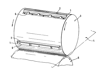
The present invention relates to a device for retaining
knife blades for cutting, perforation or other treatment
of a running web, preferably a paper web, whereby
said web (4) runs between a rotatable knife retaining
cylinder (3) and a rotatable counter pressure cylinder
(5) and whereby the knife blade (2) and a retaining
ruler (7) for retaining the blade (2) are provided in a
slot (6) in the knife retaining cylinder (3). In order
to reduce the time for mounting the knife blades, the
retaining ruler (7) has a relative to the slot (6)
downwardly inclined wedge surface (10), through which
said ruler (7) cooperates with a corresponding downwardly
inclined wedge surface (11) on a tightening ruler (9)
disposed beside the retaining ruler in the slot (6),
and the knife blade (2) is provided, during an adjustment
manoeuvre at which the knife retaining cylinder
(3) is rotated relative to the counter pressure cylinder
(5), to be pressed downwards into the slot (6) by
said counter pressure cylinder (5), whereby the blade
(2) through a support portion (12) on the retaining
ruler (7) displaces said ruler (7) downwards relative
to the tightening ruler (9) for wedging up said rulers
(7, 9) and the blade (2) in the slot (6).


French Abstract

La présente invention porte sur un dispositif de retenue de lames de couteaux pour couper, perforer ou faire un autre traitement sur une bande continue, de préférence une bande de papier, ladite bande (4) passant entre un cylindre rotatif de retenue du couteau (3) et un cylindre rotatif de contre-pression (5), le cylindre de retenue du couteau (3) ayant une fente (6) dans laquelle sont placées la lame de couteau (2) et une règle de retenue (7) pour retenir la lame (2). Dans le but de réduire le temps de montage des lames de couteaux, la règle de retenue (7) a une surface biseautée (10) inclinée vers le bas par rapport à la fente (6), qui lui permet d'agir en conjugaison avec la surface biseautée (11) correspondante inclinée vers le bas sur une règle de serrage (9) placée à côté de la règle de retenue dans la fente (6), et la lame de couteau (2) est amenée, durant une manoeuvre de réglage lors de laquelle on fait tourner le cylindre de retenue du couteau (3) par rapport au cylindre de contre-pression (5), à être poussée vers le bas dans la fente (6) par ledit cylindre de contre-pression (5), la lame (2) déplaçant ainsi la règle de retenue (7), par le biais d'une partie d'appui (12) sur ladite règle, vers le bas par rapport à la règle de serrage (9) pour caler lesdites règles (7, 9) et la lame (2) dans la fente (6).

Claims

Note: Claims are shown in the official language in which they were submitted.


8.

The embodiments of the invention in which an
exclusive property or privilege is claimed, are
defined as follows:

1. Device for retaining knife blades for cutting,
perforation or other treatment of a running web,
preferably a paper web, whereby said web (4) runs
between a rotatable knife retaining cylinder (3) and
a rotatable counter pressure cylinder (5) and whereby
the knife blade (2) and a retaining ruler (7)
for retaining the blade (2) are provided in a slot
(6) in the knife retaining cylinder (3),
c h a r a c t e r i z e d i n that the retaining ruler
(7) has a relative to the slot (6) downwardly inclined
wedge surface (10), through which said ruler (7)
cooperates with a corresponding downwardly inclined
wedge surface (11) on a tightening ruler (9)
disposed beside the retaining ruler in the slot (6),
and that the knife blade (2) is provided, during
an adjustment manoeuvre at which the knife retaining
cylinder (3) is rotated relative to the counter
pressure cylinder (5), to be pressed downwards into
the slot (6) by said counter pressure cylinder (5),
whereby the blade (2) through a support portion (12)
on the retaining ruler (7) displaces said ruler (7)
downwards relative to the tightening ruler (9) for
wedging up said rulers (7, 9) and the blade (2) in
the slot (6).


9.
2. Device according to claim 1, c h a r a c t e r i z e d
i n that resilient means (16) are provided
to displace the rulers (7,9) in vertical direction
relative to each other after said rulers and
the knife blade (2) have been disposed in the slot
(6) and loosened, whereby it is ensured that the
rulers (7, 9) and blade (2) remain in the slot (6)
until they are wedged up therein.

3. Device according to claim 2, c h a r a c t e r i z e d
i n that the resilient means consist of
helical compression springs (16), which down below
engage the retaining ruler (7) and on top engage
the tightening ruler (9) and which are adapted, from
a compressed position, to affect the rulers (7, 9)
in vertical direction in the slot (6) relative to
each other.

4. Device according to claim 3, c h a r a c t e r i z e d
i n that the compression springs (16) are
disposed in upwardly open holes (17) in the retaining
ruler (7) and that they on top engage the lower
side of tongues (18) protruding from the tightening
ruler (9) and in over the retaining ruler (7).

5. Device according to any preceding claim,
c h a r a c t e r i z e d i n that the tightening ruler
(9) has height adjustment means (13) for determining
at which height the tightening ruler (9) shall be
set relative to the bottom (14) of the slot (6) and
that the height adjustment means (13) can be set to
alter a certain height position of the tightening
ruler (9) relative to the bottom (14) of the slot
(6) to another height position.

6. Device according to claim 5, c h a r a c t e r i z e d
i n that the height adjustment means (13)

10.

consist of screws which are screwed into the tightening
ruler (9), protrude downwards like legs and
are accessible from above for determining the height
position of the tightening ruler (9).

Device according to claim 5 or 6, characterized
i n that on the bottom (14) of
the slot (6) there is provided a protective strip
(15) of a harder material than that of the knife
retaining cylinder (3) and which the height
adjustment means (13) are adapted to engage.

Device according to any preceding claim,
c h a r a c t e r i z e d i n that the support portion
(12) of the retaining ruler (7) for the knife blade
(2) consists of a flange protruding laterally from
the lower parts of the retaining ruler (7) and the
width of which is less than the thickness of the
blade (2).

Device according to any preceding claim,
c h a r a c t e r i z e d i n that a withdrawal device
(21) can be hooked onto the retaining ruler (7) for
pulling up and loosening said ruler from the slot
(6).

Device according to any preceding claim,
c h a r a c t e r i z e d i n that stop means (19)
to ensure that the rulers (7, 9) do not accidently
fall out of the slot (6) can be provided at the end
portions of the slot (6).

Description

Note: Descriptions are shown in the official language in which they were submitted.


1. 2a'~33


DEVICE FOR RETAINING KNIFE BLADES FOR CUTTING A PAPER
WEB.

The present invention relates to a device ~or retaining
knife blades for cutting, perforation or other threat-
ment of a running web, preferably a paper web, whereby
said web runs between a rotatable knife-retaining cy-
linder and a counter pressure cylinder, whereby the

2. 200~8~3

knife blade and a retaining ruler for holding the knife
blade are provided in a slot in the knife retaining cy-
linder.

At prior art devices of the above type it takes much
too long time to brace a knife blade. Since the cylinder
in question often has si~ knife blades, there is a longer
breakdown when the knife blades must be exchanged or
adjusted. This because each retaining ruler, so called
setting ruler, has a setting screw on every tenth centi-
meter and each such screw must be tightened twice. Themounting of the knife blade is namely carried out so that
the setting screws are tightened with a dynamometric
wrench, whereafter a so called setting turn is made by
rotating the cylinder with the knife blade or blades
one turn relative to the counter pressure cylinder.
~Ihen the knife blade strikes the counter pressure cy-
linder, said cylinder press the knife blade down into
the slot to its correct position. Thereafter, the set-
ting screw is permanently tightened with a box wrench
and the device is ready for operation.

The object of the present invention is to provide a de-
vice of the above type with the improvement that it
enables a substantially quicker mounting of knife bla-
des than previou~ly. This is arrived at by providing
the device with the characterizing features of claim 1.

The device defined in claim l is remarkably time-saving
when mounting a knife blade. The screwing moments re-
quired previously are eliminated and replaced by a
wedge-up function which is automatically carried out
when the knife blade is pressed down into the slot
during the setting turn.

The invention will be further described below with
reference to the accompanying drawings, wherein

8 3 3
3.

fig. 1 is a perspective view of two devices according
to the invention mounted on a cylinder;
fig. 2 is a sectional view along the line II-II in fig. l;
fig. 3 is a cross-sectional view of the device according
to the invention at a point where the device is provi-
ded with height adjustment means;
fig. 4 is a cross-sectional view of the device accor-
ding to the invention at a point where the device is
provided with resilient means;
fig. 5 is a cross-sectional view of the device accor-
ding to the invention at a point where a withdrawal de-
vice is connected to the device according to the inven-
tion; and
fig. 6 is a longitudinal section of an end portion of
the device according to the invention.

The retaining device l shown in the drawings is adapted
for retaining a knife blade 2 on a rotatable knife retai-
ning cylinder 3. The knife blade 2 is adapted for cutting,
perforation or other treatment of a running web 4, pre-
ferably a paper web, which e.g. runs through a printingpress (not shown). The web 4 runs through a space between
the knife retaining cylinder 3 and a rotatable counter
pressure cylinder S and is shown with dashed and dotted
lines in fig. 1.

The knife retaining cylinder 3 has a number of slots 6,
normally six, for receiving knife blades therein. The
illustrated device enables mounting of the knife blade
2 with a wedge-up moment. For this purpose the retaining
device has a retaining ruler 7 which is adapted to re-
tain the knife blade against one side wall 8 of the slot6. The retaining device 1 also comprises a tightening
ruler 9 disposed beside the retaining ruler 7 and adapted
to engage the opposite side wall lO of the slot 6. The
retaining ruler 7 has a wedge surface 11 facing the
tightening ruler 9 and extending in a direction sloping
downwards relative to the slot 6. In other words, the

2~8~33
4.
wedge surface extends such that it, seen from above and
downwards, approaches the side wall 8 of the slot 6.

The wedge surface 11 of the retaining ruler 7 cooperates
with a corresponding wedge surface 11 on the tightening
ruler 9. The wedge surface 11 also extends in a down-
wardly inclined direction relative to the slot 6 and
also approaches the side wall 8 of said slot seen from
above and downwards.

The retaining ruler 7 includes a support portion 12
through which the blade 2 displaces the retaining ruler
7 during an adjustment manoeuvre. This support portion
12 may be provided on different portions of the retai-
ning ruler 7 and may have various designs. A suitable
position for the support portion 12 is down below on the
retaining ruler 7 as shown in e.g. fig. 2. The support
portion 12 may further preferably be a flange protruding
laterally from the retaining ruler 7, extending along the
entire length thereof and having a width less than the
thickness of the knife blade 2.

The tightening ruler 9 preferably has a plurality of
height ad~ustment means 13 adapted to determine at which
height the tightening ruler 9 shall be set from the
bottom 14 of the slot 6. These height adjustment means
13 can be set to alter a certain height position of the
tightening ruler 9 relative to the bottom 14 of the slot
6 to another height position. The height adjustment
means 13 may be of a suitable type and be disposed in a
suitable manner. An example of a preferred hei8ht adjust-
ment means 13 is a screw which is screwed into the tighte-
ning ruler 9 and protrudes downwards as a leg throughwhich the tightening ruler 9 engages the bottom 14 of
the slot 6 or suitably a protective strip 15 on the bot-
tom 14 of the slot 6 and of a harder material than the
material in the knife retaining cylinder 3. The head

'"' 20088~
s.
of the screw 13 is accessible from above 90 that th~
screw can be screwed down or up with a tool, whereby
the tightening ruler 9 can be lowered or raised in the
slot 6.

In order to ensure that the rulers 7, 9 and knife
blade 2 remain in the slot 6 until they are wedged up
therein, resilient means 16 are provided to displace
the rulers 7, 9 vertically relative to each other. These
resilient means 16 (there are preferably a plurality
thereof) are compressible by manually displacing the
retaining ruler 7 upwards relative to the ti8htening
ruler 9 until the total width of both rulers 7, 9 and
the blade 2 is less than that of the slot 6. The rulers
7, 9 with the blade 2 are in this condition insertable
into the slot 6, whereafter they are released. Thereby,
the resilient means 16 will displace the retaining ruler
7 relative to the tightening ruler 9, which means that
the total width of said rulers 7, 9 and the knife blade
is increased to until they are fixed in the slot 6. The
resilient means preferably consist of helical compres-
sion springs 16 which down below engage the retaining
ruler 7 and on top engage the t;~ht~ning ruler 9. These
compression springs 16 are adapted, from a position in
which they are compressed, to displace the retaining
ruler 7 downwards relative to the tightening ruler 9.
The compression springs 16 are preferably positioned in
up~ardly open holes 17 in the retaining ruler 7 and on top
they engage the lower sides of tongues 18 protruding
from the tightening ruler 9 and in over the retaining
ruler 7. The mounting of the knife blade 2 in the knife
retaining cylinder 3 is carried out by inserting the
rulers 7, 9 and the blade 2 into the slot 6 as defined
above. Thereby, the height adjustment means 13 of the
tightening ruler 9 have been preset such that the blade
2 through the retaining ruler 7 will be in a position
some~hat above its final cutting position. Thereafter,

6. ~D8833

stop means 19 are screwed onto both end portions of
the slot 6 by means of screws 20. These stop ~eans 19
see to that the rulers 7, 9 can not accidentally fall
out of the slot 6 during operation.

5 Thereafter, an adjusting step takes place during which
the knife retaining cylinder 3 is rotated a so called
setting turn relative to the counter pressure cylinder
5. Thereby, the edge of the blade 2 will strike the
counter pressure cylinder 5, the peripheral surface
10 which press the blade 2 downwards to its cutting posi-
tion. During this down-stroke pressing the blade 2 will
press the retaining ruler 7 downwards through the sup-
port portion 12, which means that the rulers 7, 9 and
blade 2 Putomatically ~edge up in the slot 6 with
15 strength.

The retaining device 1 described above permits a very
quick and safe mounting of knife blades 2 on the knife
retaining cylinder 3 and it also ensures that the blade
2 is fixed in the exact correct position in the slot 6.

20 The rulers 7, 9 must of course be possible to loosen
when required and this loosening may be carried out
by means of a suitable withdrawal device 21 ~ee fig. 5).
Such a device may consist of a bracket 22 through which
a screw 23 is threaded. The bracket 22 also has two
25 pivotally mounted hook means 24 with hook portions 25
which from above are insertable into apertures 26 in
the retainjng ruler 7 to be hooked thereon. When the
hook means 24 are hooked onto the retaining ruler 7,
the screw 23 is screwed towards the tightening ruler 9
30 from above and thereby, the retaining ruler 7 is drawn
upwards to the tightening ruler 9, which means that
the keyed joint loosens and the blade 2 can be removed
from the slot 6 for replacement or adjustment.

200883~
7.
The invention is not limited to the embodiment de9cribed
above and shown in the drawings, but may vary within the
scope of the following claims. As an example of an al-
ternative embodiment could be mentioned that the web
can be of another material than paper, e.g. plastic;
the resilient means may be of another type than helical
compression springs. Finally, it can be mentioned that
the height adjustment means are easily adjusted for adap-
ting the height of the tightening ruler 9 in the slot 6.
Hereby, the height adjustment means may e.g. be set such
that the tightening ruler 9 is in position for mounting
new dull knife blades. Additionally, the height adjust-
ment means may be set such that the tightening ruler 9
is in a position higher up in the slot for mounting a
sharpened or resharpened, i.e. somewhat lower knife blade.

Representative Drawing
A single figure which represents the drawing illustrating the invention.
Administrative Status

For a clearer understanding of the status of the application/patent presented on this page, the site Disclaimer , as well as the definitions for Patent , Administrative Status , Maintenance Fee  and Payment History  should be consulted.

Administrative Status

Title Date
Forecasted Issue Date 1998-05-12
(22) Filed 1990-01-29
(41) Open to Public Inspection 1990-08-06
Examination Requested 1996-12-24
(45) Issued 1998-05-12
Deemed Expired 2003-01-29

Abandonment History

There is no abandonment history.

Payment History

Fee Type Anniversary Year Due Date Amount Paid Paid Date
Application Fee $0.00 1990-01-29
Maintenance Fee - Application - New Act 2 1992-01-29 $50.00 1992-01-08
Maintenance Fee - Application - New Act 3 1993-01-29 $50.00 1993-01-05
Maintenance Fee - Application - New Act 4 1994-01-31 $50.00 1994-01-07
Maintenance Fee - Application - New Act 5 1995-01-30 $75.00 1994-12-15
Maintenance Fee - Application - New Act 6 1996-01-29 $75.00 1996-01-18
Maintenance Fee - Application - New Act 7 1997-01-29 $75.00 1997-01-17
Maintenance Fee - Application - New Act 8 1998-01-29 $75.00 1998-01-07
Final Fee $150.00 1998-01-27
Maintenance Fee - Patent - New Act 9 1999-01-29 $75.00 1999-01-19
Maintenance Fee - Patent - New Act 10 2000-01-31 $100.00 2000-01-20
Maintenance Fee - Patent - New Act 11 2001-01-29 $100.00 2001-01-02
Owners on Record

Note: Records showing the ownership history in alphabetical order.

Current Owners on Record
STROMBERG, SVEN ARNE ROLAND
LARSSON, ROLF ARNE
Past Owners on Record
None
Past Owners that do not appear in the "Owners on Record" listing will appear in other documentation within the application.
Documents

To view selected files, please enter reCAPTCHA code :


To view images, click a link in the Document Description column. To download the documents, select one or more checkboxes in the first column and then click the "Download Selected in PDF format (Zip Archive)" or the "Download Selected as Single PDF" button.

List of published and non-published patent-specific documents on the CPD .

If you have any difficulty accessing content, you can call the Client Service Centre at 1-866-997-1936 or send them an e-mail at CIPO Client Service Centre.


Document
Description 
Date
(yyyy-mm-dd) 
Number of pages   Size of Image (KB) 
Drawings 1993-11-02 4 102
Description 1993-11-02 7 239
Cover Page 1993-11-02 1 14
Abstract 1993-11-02 1 30
Claims 1993-11-02 3 93
Cover Page 1998-04-30 2 79
Representative Drawing 1998-04-28 1 9
Correspondence 1998-01-27 1 40
Prosecution Correspondence 1996-12-24 1 35
Prosecution Correspondence 1997-03-21 1 33
Fees 1994-12-15 1 43
Fees 1997-01-17 1 49
Fees 1996-01-18 1 52
Fees 1994-01-07 1 33
Fees 1993-01-05 1 40
Fees 1992-01-08 1 40