Language selection

Search

Patent 2009054 Summary

Third-party information liability

Some of the information on this Web page has been provided by external sources. The Government of Canada is not responsible for the accuracy, reliability or currency of the information supplied by external sources. Users wishing to rely upon this information should consult directly with the source of the information. Content provided by external sources is not subject to official languages, privacy and accessibility requirements.

Claims and Abstract availability

Any discrepancies in the text and image of the Claims and Abstract are due to differing posting times. Text of the Claims and Abstract are posted:

  • At the time the application is open to public inspection;
  • At the time of issue of the patent (grant).
(12) Patent: (11) CA 2009054
(54) English Title: QUARTER-TURN DETENT TWISTLOCK
(54) French Title: VERROU TOURNANT A CLIQUANT QUART DE TOUR
Status: Deemed expired
Bibliographic Data
(52) Canadian Patent Classification (CPC):
  • 24/58
(51) International Patent Classification (IPC):
  • F16B 21/08 (2006.01)
  • A44B 99/00 (2010.01)
  • A45C 13/12 (2006.01)
  • F16B 21/02 (2006.01)
(72) Inventors :
  • FRANO, FRANCIS G. (United States of America)
(73) Owners :
  • ILLINOIS TOOL WORKS INC. (United States of America)
(71) Applicants :
(74) Agent: FINLAYSON & SINGLEHURST
(74) Associate agent:
(45) Issued: 1998-12-22
(22) Filed Date: 1990-01-31
(41) Open to Public Inspection: 1990-08-09
Examination requested: 1994-09-29
Availability of licence: N/A
(25) Language of filing: English

Patent Cooperation Treaty (PCT): No

(30) Application Priority Data:
Application No. Country/Territory Date
307,918 United States of America 1989-02-09

Abstracts

English Abstract


A twistlock fastener is constructed of a latching member and a
base member. The base member has a socket portion with a
square-shaped internal bore. The latching member is formed with head
portion and a shank portion. The shank portion has a
cylindrical section adjacent to the head portion and has a pair
of resilient bifurcated leg elements integrally formed with the
cylindrical section. Each of the leg elements have a radial
surface to provide a latching shoulder. Each latching lateral
shoulder is formed with a width sufficient to retain the shank
portion in the square-shaped internal bore. Each of the opposite
side surfaces at the opposite ends of the latching shoulder for
both leg elements lie in a common flat plane which is
perpendicular to the latching shoulders. The surface on each of
the leg elements that extends axially from and adjacent to each
latching shoulder is flat, and the corner surfaces along each of
the leg elements adjacent to each of the opposite side surfaces
are rounded along the length of the leg elements.


French Abstract

Verrou tournant constitué d'un élément de verrouillage et d'un élément de base. L'élément de base possède un emboîtement présentant un alésage interne en carré. L'élément de verrouillage comprend une tête et une tige. La tige possède une section cylindrique qui est adjacente à la tête, ainsi qu'une paire de pattes bifurquées et résilientes formées intégralement avec la section cylindrique. Chacune des pattes présente une surface radiale fournissant un épaulement de verrouillage. Chaque épaulement latéral de verrouillage est de largeur suffisante pour retenir la tige dans l'alésage en carré. Chacune des surfaces latérales opposées aux extrémités opposées de l'épaulement de verrouillage des deux pattes repose en un plan plat commun qui est perpendiculaire aux épaulements de verrouillage. La surface de chacune des pattes s'étendant axialement depuis chacun des épaulements, et qui sont adjacentes à ceux-ci, est plane. Les surfaces de coin le long de chacune de ces pattes adjacentes à chacune des surfaces latérales opposées sont arrondies sur la longueur des pattes.

Claims

Note: Claims are shown in the official language in which they were submitted.


The embodiments of the invention in which an exclusive property or
privilege is claimed are defined as follows:

1. A twistlock fastener comprising a latching member and a
base member, said base member having a socket portion with a
square-shaped internal bore, said latching member comprising a
head portion and a shank portion, said shank portion having a
cylindrical section with one end adjacent to said head portion and
a pair of resilient leg elements connected to the other end of
said cylindrical section, each of said leg elements including a
latching shoulder, said shoulders extending in opposite radial
directions from an axis of said shank portion, the length of said
shoulder across each leg element being slightly less than the
length of a side wall of said square-shaped bore, each of said
shoulders being of a width in said radial directions sufficient to
retain said shank portion in said square-shaped bore, opposite
side surfaces of said leg elements each lying in a common flat
plane perpendicular to and at opposite ends of said shoulders, the
surface on each of said leg elements which extends axially from
said shoulder at an intermediate location being flat and being
perpendicular to said common flat planes and the corner surfaces
formed along and adjacent to each of said opposite side surfaces
being rounded to permit the rotation of said latching member
relative to said base member.

2. A twistlock fastener as defined in claim 1, wherein said
flat surface on each of said leg elements extends axially to the
juncture with said cylindrical section.

3. A twistlock fastener as defined in claim 2, wherein said
flat surface on each of said leg elements tapers inwardly from
said shoulder to the juncture with said cylindrical section to
define a triangular-shaped flat surface on each leg element.

4. A twistlock fastener comprising a latching member and a
base member, said base member having a socket portion with a
square-shaped internal bore, said latching member comprising a


head portion and a shank portion, said shank portion having a
cylindrical section with one end adjacent to said head portion and
resilient bifurcated leg elements integrally formed with the other
end of said cylindrical section, each of said leg elements
including a right-angled latching shoulder extending in an outward
radial direction from the axis of said shank portion, the length
of said shoulders across each of said leg elements being slightly
less than the length of a side wall of said square-shaped bore,
each of said shoulders being of a width in said radial direction
sufficient to retain said shank portion in said square-shaped
bore, said length of said shoulders being equal to approximately
the diameter of said cylindrical section, opposite side surfaces
of said leg elements each lying in a common flat plane
perpendicular to and at opposite ends of said shoulders, the
surface on each of said leg elements which extends axially from
said shoulder and intermediate its length being flat and being
perpendicular to said common flat planes and corner surfaces
formed along each of said leg elements and adjacent to each of
said opposite side surfaces being rounded along the length of said
leg elements to permit the rotation of said latching member
relative to said base member.

5. A twistlock fastener as defined in claim 4, wherein said
flat surface on each of said leg elements extends axially to the
juncture with said cylindrical section.

6. A twistlock fastener as defined in claim 5, wherein said
flat surface on each of said leg elements tapers inwardly from
said shoulder to the juncture with said cylindrical section to
define a triangular shaped flat surface on each leg element.


Description

Note: Descriptions are shown in the official language in which they were submitted.


OIIP~TER--IIJRN DETENT ~WISTLOCK
BAC~GROUND OF TE~E TNVENTION

In the design of a twistlock fastener, one of the most
important features is to have a very positive set of latching
positions so that the user will know exactly at which of the
positions the latching head is located.

Many o~ the prior art twistlock fasteners operate on the
principle of it5 latching head acting against a resilient spring
member, such as disclosed in U.S. Patents 3l344,488; 2,382,943
and 1,190,582; British Patent 10,660; Swedish Patent 176,401 and
West German Pate~t 2,161,626. The difficulty with each of these
prior art devices is that they do not provide a very positive
la~chin~ arrangement.

One twistlock fastener that has been ~ound to give a
positive set of latching positions is disclosed in U.S. Patent
4,498,827. Unfortunately, this fastening device has a very
complex design requiring exact dimensional compliance between the
latching member and the base mem~er which is dif~icult to
manufacture and assemble. Also, this patented structure does not
perform as a one-quarter turn twistlock since it has three
distinct settings for every one-quarter turn.

;: ~ This invention is directed to a novel latch member that
cooperates in a square-shaped aperture of the base member to
provide a: one-quarter turn twistlock fastener with very positive
quarter turn latching positions. The simpl.icity of the design of
this novel twistlock fastener makes it easy to manufacture and to
a~semble. ,
:: :


,
'
.


~ . .
'

(--~


SUMM~RY OF T~ ~NVENTION

~ quarter-turn twistlock fastener is constructed o~ a latching
member and a base member. The ba5e member is ~ormed with a
socket portion having a square-shaped internal boreO The
latching member has a head portion and a shank portion, where the
shank portion is formed with a cylindrical section and a pair of
resilient leg elements integrally formed with the cylindrical
~ection~ Each of the leg elements have a radial surface to
provide a latching shoulder, and the lateral shoulders are of a
width sufficient to retain the shank portion in the square-
shaped bore. Each of the opposite side surfaces of the leg
elements lie in a common fIat plane perpendicular to and at
opposite ends of latching shoulders. The surface on each of the
leg elements that extends axially from and adjacent to each
latching shoulder is substantially flat across its length and is
perpendiculax to the common flat pla:nes. The generally square
~: shaped~ shank- portion is rotatable by virtue of rounded corner
~ surfacPs being ~ormed along the length of the leg .elements
: adjacent to the opposite side surfaces.
'


::


' . :
?

- ; :

(

DESCRIPTION OF DRAWING

For a better understanding of this invention, reference may
be made to the accompanying drawing, in which:

Figure l is a *ront elevational viaw of the preferred
embodiment of this invention with the left half o~ the base
member shown in cross section;

Figure 2 is a cross sectional view of the base memher which
is depicted in Figure l;

Figure 3 is a front elevational view of the latching member
for the prQferred embodlment of this invention;

Figure 4 is a side elevational view of the latching member
taken from the right side of Figure 3;

Fîgure 5 is a cross sectional view of the latching member
taken along ~he line 5-5 of Figure 4 and looking in the direction
of the arrows;

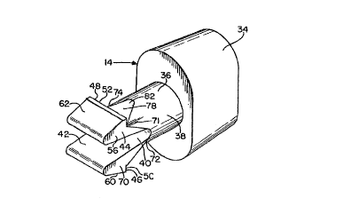
Figure 6 is perspective view of the latching member;

Figure 7 is a partial bottom plan view of the preferred
embodiment with the latching member shown in one of its two
quarter-turn positions; and

Figure 8~ is a partial bottom plan view of the preferred
embodiment with the latching member shown one-half way between
its quarter-turn pos'ltions.

:


.- :
,

.

s 2~0905~
( -

DESCRI~ ON OF PRE~ERRED EMBOI~IMENT

There is shown in Fig. 1, a twistlock fastener generally
designated by the reference 10 and incorporating the principles
of this invention. Twistlock fastener lo is constructed of a
base member 12 and latching member 14.

Base member 12 has a mounting portion 16 and socket portion
18. Th~ socket portion 18 is inteyrally formed at the center of
the oblong-shaped mounting portion 16 and is constructed as an
upstanding oval neck section 20 having a square-shaped bore 22
extending through its center area. The continuous oval-shaped
outer wall 24 of neck section 20 extends upwardly from mounting
portion 16 and is integrally connected to an oval-shaped top wall
26. A continuous internal square-shaped wall 28 is formed
integrally with the inside mar~inal edges of top wall 26 to
define square-shaped bore 22.

The length o~ the square-shaped wall 28 is substantially
less~ than the length of outer wall 24 to provide a latchin~
surface 29 at its inner end ~or retaining the latching member 14
in a ~ixed rotata~le position with respect to base member 12, as
will be explained in detail hereinafter.

On ~oth ends of soc~ek portion 18 there is provided a
mounting aperture 30, Ea~ch mounting aperture 30 is forme~ with
an enlarged upper diameter portion 32 ~or receiving the head of a
screw ~astener in a flush-mounted relation~
:
The latching member 1~4 has head portion 34 and shank portion
360 The head portion 34 can be of any cross sectional shape, but
is shown for illustration purposes as rectangular. While the
shape is not significant, it is important that its cross
sectional dimensions be greater than that of shank portion 36.

The shank portion 36 has a cylindrical section 38 formed


- ~

'
~:


.:

- 2~9~
(

adjacent head portion 34 and a leg section 40 extending axially
from the outer end of cylindrical section 38- The leg section 40
comprises a pair of bifurcated leg element~ 42 and 44. The leg
elements 42 and 44 are formed wit~ lateral radial surfaces 46 and
48, respectively, to provide latching shoulders 50 and 52,
respectively.

Latching shoulders 50 and 52 extend in radially opposite
directions from the centr~l axis of the shank portion~36. The
sidewall sur~aces 54 and 56 formed at the opposite ends of
latching shoulders 50 and 52 are general~y flat for the length
of shank portion 36, and extend generally perpendicular to
latching shoulders 50 and 52.

Referring now to Figure 1, there is shown the assembly of
the latching member 14 into the socket portion 18 of base member
12. This assembly is readily accomplished by inserting the shank
portion 36 through the square-shaped opening formed in the center
of top wall 26 into square-shaped bore 22.
,
Ramp surfaces 60 and 62 are formed on the outer ends of
resilient leg elements 42 and 44, respectively, to cause the
resilient leg elements to squeeze together as the leg elements
42, 44 are inserted inwardly into sc~are-shaped bore 22. With
the leg elements squeezed together by ramp surfaces 60 and 62,
: shanX portion 35 is pushed through bore 22 until head portion 34
i5 contiguous to top wall 26.

Because the distance from the latching shoulders 50, 5~ to
head portion 34 is slightly greater than the length of bore 22,
the latching shoulders 50, 52 will th~n extend beyond square-
shaped latching surface 29 to free the resilient leg elements 42,
44 to spring into a radial ~utward position, as shown in Fig. 1.
In this position, latching member 14 is rotatably held within
~ base member 12.
The side surfaces 54 and 56 of leg elements 42 and 44 are


.
,

" ~: ~

2 ~
: (..
formed with common flat parallel surfaces 68 and 70,
\ respectively, that extend generally perpendicular to latching
shoulders 50, 52. The distance between the common flat parallel
surfaces 68 and 70 is slightly less than the length of side walls
28 of square-shaped bore 22.

To permit the latching member 14 to be rotatable relative to
the s~uare-shaped bore 22 in base member 12, it is necessary to
have four rounded corner edges 71, 72, 73 and 74 extending
lengthwise o~ the bifurcated leg section 40 between the
]~ cylindrical section ~8 and the latching shoulders 50 and 52.

In order to provide positive q~arter-turn latching
positions, a flat surface 76 and 78 is formed on leg elements 42
and 44, respectively, inte~mediate the rounded corner edges 71-
74. The flat surfaces 76 and 78 extend from latching shoulders
~5 50 and 52, respectively, and tapers inwardly in an axial
direction to an apex at its juncture with the cylindrical section
to form triangular sections 80 and 82. The size of triangular
sections 80 and 82 determines of the amount of resistance to the
latching member being rotated to tha next position. A larger
~~ size triangular section will provide greater resistance to
rotation.

As depicted in Figure 8, a rotational force on head portion
34 in either direction causes the resilient leg elements 42 and
44 to be squeezed towards each other as the four rounded corners
71~74 engage the side wall5 28 of square-shaped bore 22. After
the latching member 14 is rotated ninety degrees, the flat
triangular sections 80 ard 82 and the common flat surfaces 58 and
70 are brought into engagement with the four side walls 28 of
bore 22 to provide a very positive quarter-turn position as shown
in Figure 7.

From the foregoing description, it will be appreciated that
the rounded corners 71-74 on resilient leg elements 42 and 44

09~
(. (

permit the latching member 14 to be rotated in the square-shaped
bore 22 and that flat parallel surfaces 68 and 70 cooperate with
flat parallel sur~aces 76 and 78 (adjacent latching shoulders 50
and 52~ to provide very positive quarter-turn positions.


~' :
, . '''

~;


- , ,. ~

.: ~ , ' .':.:~ ' '

Representative Drawing
A single figure which represents the drawing illustrating the invention.
Administrative Status

For a clearer understanding of the status of the application/patent presented on this page, the site Disclaimer , as well as the definitions for Patent , Administrative Status , Maintenance Fee  and Payment History  should be consulted.

Administrative Status

Title Date
Forecasted Issue Date 1998-12-22
(22) Filed 1990-01-31
(41) Open to Public Inspection 1990-08-09
Examination Requested 1994-09-29
(45) Issued 1998-12-22
Deemed Expired 2004-02-02

Abandonment History

There is no abandonment history.

Payment History

Fee Type Anniversary Year Due Date Amount Paid Paid Date
Application Fee $0.00 1990-01-31
Registration of a document - section 124 $0.00 1991-11-13
Maintenance Fee - Application - New Act 2 1992-01-31 $100.00 1992-01-22
Maintenance Fee - Application - New Act 3 1993-02-01 $100.00 1992-11-26
Maintenance Fee - Application - New Act 4 1994-01-31 $100.00 1993-11-12
Maintenance Fee - Application - New Act 5 1995-01-31 $150.00 1994-11-14
Maintenance Fee - Application - New Act 6 1996-01-31 $150.00 1995-11-02
Maintenance Fee - Application - New Act 7 1997-01-31 $150.00 1997-01-03
Maintenance Fee - Application - New Act 8 1998-02-02 $150.00 1998-01-20
Final Fee $300.00 1998-08-10
Maintenance Fee - Patent - New Act 9 1999-02-01 $150.00 1999-01-25
Maintenance Fee - Patent - New Act 10 2000-01-31 $200.00 2000-01-04
Maintenance Fee - Patent - New Act 11 2001-01-31 $200.00 2001-01-03
Maintenance Fee - Patent - New Act 12 2002-01-31 $200.00 2002-01-03
Owners on Record

Note: Records showing the ownership history in alphabetical order.

Current Owners on Record
ILLINOIS TOOL WORKS INC.
Past Owners on Record
FRANO, FRANCIS G.
Past Owners that do not appear in the "Owners on Record" listing will appear in other documentation within the application.
Documents

To view selected files, please enter reCAPTCHA code :


To view images, click a link in the Document Description column. To download the documents, select one or more checkboxes in the first column and then click the "Download Selected in PDF format (Zip Archive)" or the "Download Selected as Single PDF" button.

List of published and non-published patent-specific documents on the CPD .

If you have any difficulty accessing content, you can call the Client Service Centre at 1-866-997-1936 or send them an e-mail at CIPO Client Service Centre.


Document
Description 
Date
(yyyy-mm-dd) 
Number of pages   Size of Image (KB) 
Representative Drawing 1998-12-15 1 8
Claims 1997-12-24 2 96
Cover Page 1998-12-15 1 60
Cover Page 1994-04-01 1 20
Abstract 1994-04-01 1 39
Claims 1994-04-01 2 115
Drawings 1994-04-01 1 51
Description 1994-04-01 7 311
Correspondence 1998-08-10 1 39
Office Letter 1991-04-02 1 62
PCT Correspondence 1991-07-03 1 29
Office Letter 1994-10-14 1 67
Prosecution Correspondence 1994-09-29 1 42
Prosecution Correspondence 1997-12-01 2 46
Examiner Requisition 1997-06-03 2 80
Fees 1997-01-03 1 49
Fees 1995-11-02 1 42
Fees 1992-11-26 1 48
Fees 1992-01-22 1 32
Fees 1994-11-14 1 48
Fees 1993-11-12 1 55