Note: Descriptions are shown in the official language in which they were submitted.
- 1 - 2~9129
IMAGE PICKUP HEAD FOR IMAGE PICKUP DEVICE
This invention relates to an image pickup head for
an image piCkUp device adapted to pick up an image of
the surface of a subject in various fields such as
medical fields, industrial fields and the like.
Image pickup devices which are adapted to abut
have connected to them an image pickup head including
built-in light projecting means for illumlnating the
surface of a section to be observed (hereinafter
referred to as an "observed section") of a subject in
order to display a magnified image of the surface of
the observed section at a monitor image plane, have
been used in various fields. In such image pickup
devices, it is essential that illumination of the
surface of the observed section is appropriately and
accurately carried out.
More particularly, illumination mainly comprising
light which is vertically projected onto the surface of
the observed section of a subject against which the
image pickup head is abutted (hereinafter referred to
as "abutment surface") tends to cause the reflection of
the light on the abutment surface of the subject to be
increased. This results in the image of that portion
of the abutment surface at which the reflection of
light is increased appearing white on a monitor image
plane for displaying a magnified image of the abutment
surface, leading to a failure in the satisfactory
observation of details of the abutment surface of the
subject, such as its colour, its overall configuration
and the like.
Illumination mainly using horizontally projected
2~9129
-- 2
light, i.e. light which is projected parallel to the
abutment surface of the observed section of a subject
generally fails to illuminate satisfactorily fine
recesses which might exist on the abutment surface.
Thus, a finely recessed portion of the abutment surface
would appear relatively dark on a monitor image plane
for displaying a magnified image of the abutment
surface! resulting in an inability to observe fine in
the abutment surface of the subject.
In order to alleviate these problems, the present
applicants proposed a light guiding device for
illumination suitable for displaying a magnified image
of the observed surface of a subject including fine
recesses, as disclosed in European Patent Application
No. 89.305570.7.
The proposed light guiding device is adapted to be
used with an image pickup head and is constructed so as
to eliminate the adverse effect of light reflected on
the surface of the observed section of a subject, to
permit a three-dimensional magnified image of the
surface to be satisfactorily displayed on a monitor
image plane. Unfortunately, elimination of light
reflected on the observed surface renders the
observation of light reflection on the surface
substantially impossible.
This will now be considered in connection with the
observation of the surface of the skin of the human
body. The so-called "shining condition" of the skin
such as the complexion and glow of the surface of the
skin vary depending upon the health condition of ~he
skin, the degree of aging of the skin and so on.
Therefore, the "shining conditions" of the skin are
2~1,~t
u~eful ln determlnin~ ~he condltlon of the skln. The
detectlon of the shinlng conditlon of the skin for thls
purpose can be carried out on ~he basls of the degree
of reflectlon of light at the skin ~urface. hus,
although lt is generally effectlve and deslrable to
ellminate the reflectlon of light at the surface of the
observed section of a ~ubJect in order to observe the
sub~ect accurately, lt ls also desirable to make the
detectlon of light reflectlon at the surface of the
observed section possible.
Furthermore, the lmage obtalned of the observed
sectlon of a sub~ect when accompanied by llgh~:
reflected at the observed section, sa~lsfactorlly shows
the three-dimensional or stereo configuratlon of the
observed sec~lon, whereas the lmage of the ob~ierved
section whlch i~ free of reflected light effec:tively
lndlcate~ the colour of the ob6erved sectlon. In the
latter case, for example, when the observed sectlon i3
the ~kln of a human body, a part of light pro;jected
onto the skin penetrate~ the outer layer of the ~kln,
thereby causlng the structure of the outer layer to be
clearly observed.
Accordingly, the present învention has concluded
that the substantlally simultaneous observation of both
an image of the subject accompanled by light reflected
at the surface of the observed section and an lmage
thereof free of reflected light slgnlficantly
contrlbutes to the detectlng of or finding cell~ in
which a cancer may have developed, and the like. The
present lnvention has been made ln view of the
foregoing.
Accordlngly, lt ls an obJect of the present
2~129
invention to provide an image pickup head for an image
pickup device which is capable of permitting the
observed section of a subject to be illuminated with as
uniform an illuminance as possible.
It is another object of the present invention to
provide an image pickup head for an image pickup device
which is capable of permitting a magnified image of the
observed section of a subject to be effectively
displayed while preventing the reflection of light at
the observed section from adversely affecting the
image, as well as permitting the degree of the light
reflection to be detected.
It is a further object of the present invention to
provide an image pickup head for an image pickup device
which is capable of permitting an image of the observed
section of a subject accompanied by light reflected at
the surface of the observed section, and an image of
the same observed section free of the reflected light,
to be selectively displayed while being instantanously
changed over as required.
In accordance with the present invention, there is
provided an image pickup head for an image pickup
device comprising: a head body; an optical system
within the head body; an image pickup element in the
head body arranged to pick up an optical image
introduced through the optical system; and a light
guide located annularly about the optical axis of the
optical system in the head body arranged to project
light for illumination supplied from a light source
through the projection end of the light guide on to the
surface of a subject; characterised by: a first
polarizing element having a predetermined polarization
2~V91 .~",9
-- 5
plane, arranged in the optical path of light projected
from the projection end of the light guide onto the
subject; a second polarizing element having a
predetermined polarization plane, arranged on the
optical path of light reflected at the subject and
guided to the image pickup element; and operative means
for varying the polarization planes of first and second
polarizing elements relative to each other.
In a preferred embodiment of the present
invention, the operation means comprises rotation means
for rotating any one of the first and second polarizing
elements about the optical axis of the optical system
to vary their polarization planes relative to each
other.
Alternatively, the operation means may comprise a
slide system for causing at least one second polarizing
plate, having a predetermined polarization plane
crossing the polarization plane of a first polarizing
plate, to enter retractably the optical path of the
reflected light.
In an alternative embodiment of the present
invention, the second polarizing element has a
predetermined polarization plane crossing the
polarization plane of the first polarizing element and
is arranged in the optical path of light reflected at
the subject and guided to the image pickup element, and
a rotation element is provided on the side of the first
or second polarizing element facing the subject
arranged to rotate the polarization plane of one of the
first and second polarizing elements relative to the
polarization plane of the other polarizing element.
2~ 29
-- 6
In a preferred embodiment of the present
invention, the rotation element comprises a liquid
crystal element. Alternatively, the rotation element
may comprise a PLZT.
The invention may be carried into practice in
various ways and some embodiments will now be described
with reference to the accompanying drawings in which:-
Figure 1 is a schematic front elevatlon, partly lnsection, showing a first embodiment of an image pickup
head for an image pickup device according to the
present invention;
Figure 2 is a view similar to Figure 1 showing a
second embodiment;
Figure 3(a) is an exploded perspective view
showing a polarization panel comprising a combination
of polarizing plates and a liquid crystal element;
Figure 3(b? is a sectional view of the
polarization panel shown in Figure 3(a);
Figure 3(c) is a front elevation of the
polarization panel shown in Figure 3(a);
Figure 4 is a schematic sectional view of the
liquid crystal element shown in Pigure 3(a);
Figure 5(a) is a fragmentary schematic vertical
sectional view showing the essential part of third
embodiment of an image pickup head for an image pickup
device;
2~91~
Figure 5(b) is a sectional view taken along line
Vb-Vb of Figure 5(a);
Figure 6(a) is a fragmentary schematic vertical
sectional view showing the essential part of a fourth
embodiment of an image pickup head for an image pickup
device; and
Figure 6(b) is a sectional view taken along line
VIb-VIb of Figure 5(a).
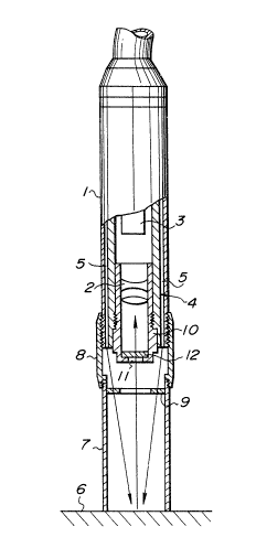
Figure 1 shows a first embodiment of an image
pickup head for an image pickup device according to the
present invention. The pickup head includes a head
body comprising a lens barrel or tube 1, in which a
magnifying optical system 2 is located. The lens tube 1
also houses an image pickup element of CCD image sensor
3 for converting an optical image formed ~hrough the
magnifying optical system 2 into an electrical signal.
For this purpose, the image pickup element 3 is
positioned at the proximal end of the lens tube 1 and
is connected to a display unit (not shown) including a
monitor image plane for displaying a magnified image
obtained through the image pickup element 3.
The image pickup head also includes a plurality of
optical fibres 5 on the inner surface of the lens tube
1 located about the optical axis of the magnifying
optical system 2 so as to form a part of the lens tube
1. The optical fibres 5 are annularly arranged in a
manner to surround the magnifying optical system 2 and
be close to one another, thus forming a light guide 4.
The light guide 4 is so arranged that its distal end
terminates at the distal end of the lens tube 1. The
optical fibres 5 are bundled in front of a light source
2~91,~,9
-- 8
(not shown) and then guided to the proximal end of the
lens tube 1. Then, the optical fibres 5 extend towards
the distal end of the lens tube 1 while being evenly
arranged in such a way that they are annularly close to
one another. Such an arrangement of the light guide 4
permits light projected from the light guide 4 onto the
surface of the observed section of a subject 6 to
illuminate the surface uniformly.
The image pickup head also includes an objective
contact member 7 of a cylindrical configuration which
is threadedly connected to the distal end of the lens
tube 1 through a cylindrical member or ring 8 which is
itself threadedly connected to the lens tube 1. The
axial position can then be varied for the adjustment of
focus of the head. The objective contact member 7
extends in the direction of the optical axis of the
magnifying optical system 2 and engages the ring 8
about the optical axis of the magnifying optical system
2. The objective contact member 7 has an opening at
its distal end, which is brought into contact with the
surface of the observed section of the subject 6 to
stabilise the positional relationship between the lens
tube 1 and the surface of the observed section of the
subject 6 with this arrangement, the objective contact
cylinder 7 can be rotated relative to the lens tube 1,
resulting in the focus of the lens tube 1 or magnifying
optical system 2 and therefore the image pickup head
being adjusted.
In the illustrated embodiment, the objective
contact member 7 has a cylindrical shape. However, it
may be formed into any other suitable shape depending
upon the properties of the surface of the observed
section of the subject 6. For example, it may be
2~9129
expanded or constricted at its distal end.
The image pickup head further includes a first
polarizing element or plate 9 having an annular shape
located in the objective contact member 7. The first
polarizing plate 9 is positioned in the optical path of
light discharged from the distal end or projection end
of the light guide 4 towards the surface of the
observed section of the subject 6, so that light from
this distal end of the light guide 4 passes through the
first polarizing plate 9 for illuminating the surface
of the subject 6. The image pickup head also includes
a second polarizing element or plate 12 of a circular
shape positioned in the optical path of light reflected
at the observed section of the subject 6 and directed
towards the image pickup element 3. In the illustrated
embodiment, the second polarizing plate 12 is located
inside an opening 11 in a mounting cylinder 10 in which
the magnifying optical system 2 is housed.
The operation of the image pickup head of the
first embodiment will now be described.
First, for the purpose of observing the subject 6,
the objective contact member 7 is placed in contact
with the surface of the observed section of the subject
6 and then rotated to cause movement in the axial
direction, resulting in adjustment of the focus of the
image pickup head.
Light for illumination is radiated from the light
source (not shown) and is annularly uniformly
discharged from the optical fibres 5 constituting the
light guide 4 and permeates through the first
polarizing plate 9, positioned in the optical path of
- 10 - 2~9129
the light, so that the light is linearly polarized.
This results in the light illuminating the abutment
surface or the observed surface of the subject 6 with a
substantially uniform illumination. Thus, it will be
noted that the image pickup head of the illustrated
embodiment may accomplish satisfactory illumination on
the abutment surface of the subject 6 even when any
unevenness exists on the abutment surface.
Light reflected at the abutment surface of the
observed section of the subject 6 is linearly or
straightly polarized light having been polarized by
the first polarizing plate 9, and has a polarization
plane in a specific vector direction. Also, the
portion of the polarized light reaching the interior of
the subject through the abutment surface is reflcted
within the interior after being changed, at the
abutment surface, into circularly polarized light
having a polarization plane in every direction
corresponding to the configuration of the abutment
surface. Thus~ the linearly polarized light reflected
on the abutment surface and the circularly polarized
light reflected within the interior of the subject 6
are guided together to the second polarizing plate 12,
which either allows only the linearly polarized light
to permeate through or removes it, so that either only
the linearly polarized light or only the circularly
polarized light may be selectively guided through the
magnifying optical system 2 to the image pickup element
3. This results in a magnified image of the abutment
surface being supplied to the image pickup element 3.
Thus, in this first embodiment, turning the
objective contact member 7 causes the first polarizing
plate 9 and second polarizing plate 12 to be rotated
2~9129
relative to each other, leading to a deviation between
the polarization planes of the two polarizing plates.
Adjustment of the relative angle between the polarizing
plates 9 and 12 may readily selectively provide an
output for the image pickup element 3 which is either
accompanied by, or free of, light reflected at the
abutment surface of the subject 6.
The elimination of light reflected at the abutment
surface from the output permits the colour at the
abutment surface of the observed section to be observed
highly distinctly. When, for example, the skin of a
human body is to be observed, this permits the --
conditions of the skin such as the conditions of
capillary vessels, the rubescence of the skin, the
precipitation of a pigment in the skin, a change to the
morbid state and the like to be readily diagnosed.
Furthermore, when it is required to detect the degree
or amount of light reflected at the abutment surface
for the purpose of observing, for example, the "shining
condition" of the skin as described above, a comparison
between the output for the image pickup element free of
light reflected at the abutment surface and that
accompanied by the light, which are obtained by
rotating the first and second polarizing plates 9 and
12 relative to each other, can be carried out,
resulting in the quantitative detection of the "shining
condition" being facilitated.
Thus, the image pickup head of the first
embodiment permits a magnified image of the abutment
surface of the subject 6 to be distinctly formed at the
light receiving plane of the image pickup element 3,
and is then displayed on the image plane of a monitor
display device such as a TV monitor. The image pickup
2~9129
- 12 -
head is suitable not only for a magnifying observation
of the tissues of the skin or an organ of a human body
but also the observation of various kinds of subjects,
by constructing the objective contact member
appropriately to each of ~he subjects.
In this first embodiment, relative rotation
between the first polarizing plate 9 and the second
polarizing plate 12 is carried out manually. However,
the present invention may be constructed so as to carry
out this relative rotation automatically.
Figures 2 to 4 show a second embodiment of an
image pickup head according to the present invention,
which is adapted to carry out relative rotation between
the two polarizing plates automatically and rapidly.
The image pickup head of the second embodiment
includes a head body comprising a lens barrel or tube
1, in which a magnifying optical system 2 is housed, as
in the first embodiment. Also, the lens tube 1 has an
image pickup element 3 for converting an optical image
formed through the magnifying optical system 2 into an
electrical signal. For this purpose, the image pickup
element 3 is located at the proximal end of the lens
tube 1 and connected to a monitor display unit such as
a TV monitor (not shown) including an image plane for
displaying the magnified image obtained through the
image pickup element 3.
The image pickup head also includes a plurality of
optical fibres 5 on the inner surface of the lens tube
1 arranged about the optical axis of the magnifying
optical system 2. The optical fibres 5 are annularly
arranged in a manner to be close to one another and
- 13 - 2 ~92 29
surround the magnifying optical system 2, thus forming
a light guide 4. The light guide 4 is so arranged that
its distal end terminates at the distal end of the lens
tube 1. The optical fibres 5 are bundled in front of a
light source (not shown) and then guided to the
proximal end of lens tube 1. Then, the optical fibres
5 extend towards the distal end of the lens tube 1
while being evenly arranged in such a way that they are
annularly close to one another. Such an arrangement of
the light guide 4 permits light discharged from the
light guide 4 to illuminate uniformly the surface of
the observed section of a subject 6.
The lens tube 1 is so formed that its distal end
protrudes by an amount required for the adjustment of
the focus of the image pickup head, resulting in the
provision of an objective contact member 7 of
cylindrical shape which extends in the direction of the
optical axis of the magnifying optical system 2. The
objective contact member 7 has at its distal end an
opening, which is brought into contact with the surface
of the observed section of the subject 6 to stabilise
the positional relationship between the lens tube 1 and
the subject 6. Also, the objective contact member
serves to block any foreign or external light from
entering the image pickup head.
In this embodiment, the objective contact member
7, as described above, is connected directly to the
lens tube 1. However, it may be connected to the
distal end of the lens tube 1 through a cylindrical
member or ring 8 adapted to be threadedly adjusted for
the adjustment of focus of the lens tube as in the
first embodiment. In the second embodiment, the
objective contact member 7 has a cylindrical shape as
2~99~ 9
- 14 -
in the first embodiment. However, it may be formed
into any other suitable shape depending upon the
properties of the abutment surface of the observed
section of the subject 6.
For example, it may be expanded or constricted at
its distal end.
In the second embodiment, as shown in Figure 2 to
4, a first polarizing plate 9 i5 provlded, contlguous
with an opening 11 in a mounting cylinder 10 for the
magnifying optical system 2. The first polarizing
plate 9 is annular and arranged coaxially with the
optical axis of the magnifying optical system. It is
positioned in the optical path of light for illumination
discharged from the distal end or projection end of the
light guide towards the subject, so that the light
discharged from the light guide 4 may be projected on
the abutment surface of the observed section of the
subject. Also, a second polarizing plate 12 which is
circular and has a polarization plane crossing that of
the first polarizing plate 9, is arranged so as to be
combined with the first polarizing plate 9 and received
in the central opening of the first polarizing plate 9.
The second polarizing plate 12 is positioned in the
optical path of light reflected from the subject 6. On
the subject side of the combination of the first and
second polarizing plates 9 and 12, there is a liquid
crystal element 13 which is contiguous with the second
polarizing plate 12 so that it serves as a rotation
element for rotating the polarization plane of the
polarizing element or plate. An A.C. oscillator 17 is
connected to the liquid crystal element 13 for applying
a D.C. voltage to control the rotation of the
polarization plane across a liquid crystal material
2~9129
- 15 -
(described below) through transparent electrodes 14,
external electrodes 15 (Figure 4) and through a lead
wire 16 (Figure 2). The oscillator 17 will be
described below.
The combination of the first and second polarizing
plates 9 and 12 cooperates with the liquid crystal
element 13 to constitute a polarization panel 19 as
shown in detail in Figures 3(a) to 3(c). More
specifically, Figure 3(a) i~ an exploded perspectlve
view showing the polarization panel 19 prior to
assembly, Figure 3(b) is a vertical sectional view of
the panel 19 after assembly, and Figure 3(c) is a front
elevation of the panel 19 after assembly, viewed from
the polarization plate side.
The liquid crystal element 13, as shown in Figure
4, includes two transparent plates 20 made of a glass
material or the like and a nematic liquid crystal
material 21 interposed between the transparent plates
20. The transparent electrodes 14 are arranged on each
surface of the liquid crystal 21 and are made of tin
oxide, indium oxide or the like. The transparent
electrodes 14 are connected to the corresponding
external electrodes 15, respectively, which are then
connected through the lead wire 16 to the A.C.
oscillator 17 (Figure 2). The oscillator 17 is
connected to a control switch 22, which allows A.C.
power to be supplied from the A.C. oscillator 17 to the
transparent electrodes 14 to apply an A.C. voltage
across the liquid crystal 21, whereby the liquid
crystal element 13 readily controls rotation of the
polarization plane of the second polarizing plate 12 in
a vector direction. In addition, the control of the
applied voltage facilitates adjustment of rotation
2~ X9
- 16 -
angle of the polarization plane. It is also possible
to pass an A.C. current between the transparent
electrodes 14 in a manner to cause the phases to be
opposite to each other, thereby rendering the average
value of the voltage applied across the liquid crystal
21 zero. This tends to prolong the life of the liquid
crystal 21.
In the illustrated embodiment, it is not
necessarily required to arranged the A.C. oscillator 17
and control switch 22 directly on the image pickup
head. They may be connected through the lead wire 16
to the image pickup head. In this instance, they may
be operated by remote control. The oscillation
f}equency of the A.C. oscillator 17 is conveniently set
within the range between 300Hz and 50KHz. When the
oscillation frequency is set at a level as low as 60Hz
which is the output frequency of the monitor TV, the
image displayed on the TV monitor is accompanied by a
beat. The setting of the frequency at a level above
50KHz does not exhibit any meritorious effect and
rather causes an increase in power consumption. Thus,
the frequency is preferably set at about lKHz. This is
preferable also from the viewpoint of the manufacturing
of the oscillator 17, because an oscillator of such a
frequency is relatively easily manufactured.
The image pickup head may be constructed into any
desired size depending upon its intended use, because
the liquid crystal element 13 can readily be small-
sized.
In place of the liquid crystal 21, there may be
substituted a material capable of rotating the
polarization plane of the polarizing plate by an
- 17 - 2 ~91 29
electrical treatment such as, for example, PLZT. More
specifically, the PLZT comprising a composite material
of oxides of lead (Pb), lanthanum (La), zirconium (Zr)
and titanium (Ti) and is a transparent crystal made by
sintering the oxides in powder form under pressure.
The polarization characteristics of PLZT vary when it
is subject to electrical treatment. Alternatively, a
material which is capable of rotating the polarization
plane of the polarizing plate when magnetism is applied
to it may be used for this purpose in place of the
liquid crystal 21.
The remainder of the second embodiment may be
constructed in substantially the same manner as the
first embodiment.
The image pickup head of the second embodiment may
be operated in substantially the same way as the first
embodiment, in order to check the observed section of a
subject 6. For this purpose, the objective contact
member 7 is placed against the surface of the observed
section.
Then, light for illumination generated from a
light source (not shown) is discharged through the
optical fibres 5 of the light guide 4 from the
periphery of the magnifying optical system 2.
Thereafter, the light passes through the first
polarizing plate 9 positioned in the optical path of
the light, so that it may be subject to linear
polarization, resulting in its having a polarization
plane in a specific vector direction. This polarized
light is uniformly projected on the abutment surface of
the observed section of the subject 6 for illumination.
This causes the light to be reflected at the abutment
- 18 - 2~
surface of the subject. This reflected light, as
described above, is linearly polarized light with a
polarization plane in a specific vector direction due
to its polarization through the polarizing plate 9. A
part of the polarized light reaches the interior of the
subject 6 through the abutment surface and is reflected
within the interior. It is therefore changed, at the
abutment surface, into circularly polarized light,
having a polarization plane in every direction
corresponding to the conflguration of the ab~tment
surface. The linearly polarized light reflected at the
abutment surface and the circularly polarized light
reflected within the interior of the subject 6 are
guided to the liquid crystal element 13. If no voltage
is applied from the oscillator 17, the liquid crystal
element 13 causes the direction of the polarization
plane of the reflected light to be rotated by a
predetermined angle, so that only reflected light
having a polarization plane in the same vector
direction as the linearly polarized and reflected light
may be permitted to permeate through the second
polarizing plate 12 and reach the image pickup head 3
through the magnifying optical system 2.
On the other hand, when a voltage is applied from
the oscillator 17, the polarization direction of the
reflected light is not caused to be rotated.
Accordingly, the reflected light permeates through the
liquid crystal element 13 while leaving the
polarization direction of the linearly polarized light
as it is without changing the vector direction, so that
the reflected light fails to permeate through the
second polarizing plate 12. Thus, only that portion of
the light reflected within the interior of the subject,
from which the light reflected at the abutment surface
2~2,~3
- 19 -
of the subject which has a polarization plane in the
vector direction is removed, permeates through the
second polarizing plate 12 and is guided through the
magnifying optical system 2 to the image pickup element
3.
Thus, it will be noted that the image pickup head
of the second embodiment selectively provides either an
output for the image pickup element which contains
light reflected at the abutment surface of th~ s~lb~ct
6, or an output for the image pickup element from which
only the reflected light is removed, as required.
Also, the illustrated embodiment permits the selection
to be instantaneously carried out by the on-off control
of the oscillator 17. Accordingly, it eliminates any
necessity to keep the subject 6 stationary, so that an
image of the abutment surface accompanied by the light
reflected at the surface and that free of the reflected
light may be substantially concurrently observed. This
permits the image pickup head to be operated in
association with a device in which an electrical image
is taken such as, for example, an image processing
device, an image recording device or the like, so that
an image of the observed section of the subject 6
accompanied by the reflected light and that free of the
reflected light may be substantially simultaneously
obtained with a time difference as small as ten
milliseconds.
In this instance, although the output for the
image pickup element which is accompanied by light
reflected at the abutment surface of the observed
section of the subject 6 facilitates the observation of
unevenness of the surface, it fails to permit the
colour of the surface or the like to be distinctly
9~2g
- 20 -
observed. However, the application of a voltage across
the liquid crystal element 13 causes light reflected at
the surface of the observed section to be eliminated
from the image, resulting in the colour of the surface
being distinctly observed to a degree sufficient to
ensure accurate observation of the subject.
In the second embodiment, the arrangement of the
first and second polarizing plates 9 and 12 may be
carried out in any desired manner as long as the first
polarizing plate 9 is positioned in the optical path of
the projected light and the second polarizing plate 12
is positioned in the optical path of the reflected
light.
Figures 5(a) and 5(b) show a third embodiment of
an image pickup head according to the present
invention. It is constructed so as to eliminate light
reflected at the surface of the observed section of a
subject without using a liquid crystal element as in
the second embodiment.
In the third embodiment, as shown in Figures 5(a)
and 5(b), a first annular polarizing plate 9 positioned
in the optical path of projected light is pivotally
supported on a cylindrical objective contact member 7
so as to be pivotally movable about the optical axis of
the image pickup head. The objective contact member 7
is formed on the outer periphery with gearing 24, of
which a part is exposed. The gearing 24 is operatively
connected through a pinion 25 to a motor 23 outside the
lens tube 1, by means of which it can be rotated. A
second polarizing plate 12 provided in the optical path
of reflected light is fixed in an opening 11 of a
mounting cylinder 10. The remainder of the third
2~`92,Y~,9
- 21 -
embodiment may be constructed in substantially the same
manner as the first embodiment.
In the image pickup head of the third embodiment,
light for illumination generated or radiated from a
light source (not shown) is guided through a light
guide 4 to the first polarizing plate 9, where it is
linearly polarized. When the first polarizing plate 9
is rotated by means of the motor 23, the vector
direction of the polarization plane of the light, which
is linearly polarized and then guided to the abutment
surface of the observed section, varied with time as
the first polarizing plate 9 rotates. The linearly
polarized light with a varying vector direction is
reflected at the abutment surface and circularly
polarized light is reflected within the interior of the
subject, are guided to the second polarizing plate 12.
The second polarizing plate 12 causes only that
portion of the circularly polarized light reflected
within the subject which has a polarization plane in a
specific direction to pass through. It also ensures
that only that portion of the linearly polarized light
reflected at the surface of the subject which has the
specific appropriate vector component will pass
through.
Thus, it will be noted that the image pickup head
of the third embodiment permits the proportion of light
reflected at the abutment surface of the subject which
represents the reflected light introduced to the image
pickup element to be reduced, thus providing an image
in which the light reflected at the surface of the
observed section of the subject is decreased.
20~9129
- 22 -
Figures 6(a) and 6(b) show a fourth embodiment of
an image pickup head according to the present
invention, which is adapted to eliminate light
reflected at the surface of the observed section of a
subject 6 without using a liquid crystal element as
used in the second embodiment.
In the fourth embodiment, a first annular
polarizing plate 9 located in the optical path of the
projected light is fixed on a cylindrical objectlve
contact member 7 so that its centre is aligned with the
optical axis of the image pickup head, while a second
polarizing plate 12 placed in the optical path of the
reflected right is supported in the opening 11 of a
mounting cylinder 10. It covers the opening 11 and is
slidable in a direction perpendicular to the optical
axis. The second polarizing plate 12 comprises a
combination of a polarizing plate section 12a and a
transparent polarizing plate section 12b. The
polarizing section 12a allows linearly polarized light
in a direction at an angle to the linearly polarized
light passing through the first polarizing plate 9 to
pass, while the transparent polarizing plate section
12b allows linearly polarized light in the same
direction as the linearly polarized light passing
through the first polarizing plate 9 to pass, or is
free of any polarization properties. This second
polarizing plate 12 has on one side a slide member 27,
which is arranged so as to project or extend outside
the objective contact member 7. It is constantly
elastically abutted against a cam 26 driven through a
motor 23 located outside a lens tube 1 by means of a
spring 29. In this embodiment~ the use of the
transparent polarizing plate section 12b permits the
difference in brightness between an image accompanied
2~9~29
- 23 -
by reflected light and one free of reflected light to
be significantly reduced.
The remainder of the fourth embodiment is
substantially the same as the first embodiment.
In the image pickup head of the fourth embodiment,
light for illumination radiated from a light source
(not shown) is guided through a light guide 4 to the
first polarizing plate 9, where it ls linearly
polarized. When the motor 23 is driven, the sections
12a and 12b of the second polarizing plate 12 are
reciprocated in a plane perpendicular to the optical
path of the reflected light, so that the polarizing
plate sections 12a and 12b enter the optical path
alternately.
Such an arrangement causes the ratio of permeation
of the linearly polarized light through the polarizing
plate 9 and then reflected at the surface of the
observed section of the subject 6 to be decreased, so
that reflected light from which a significant
proportion of the light reflected at the abutment
surface of the subject is removed may be introduced to
the image pickup element, resulting in an image being
obtained in which the light reflected on the abutment
surface is greatly reduced.
Each of the ima~e pickup heads of the present
invention described above permits an image of a desired
magnification to be obtained, determined by the
magnifying optical system selected. It has been found
that all the above-described embodiments allow the
image to be magnified fifty to two hundred times.
~912g
- 24 -
As can be seen, an image pickup head in accordance
with the present invention selectively provides an
output for the image pickup element, either accompanied
by light reflected at the surface of the observed
section of a subject, or substantially decreased in or
free from such reflected light. Also, the image pickup
head of the present invention permits the outputs to be
instantaneously changed. Thus, the present invention
eliminates any necessity to keep a subject stationary,
resulting in the possibility of an lmage of the subJ~ct
accompanied by light reflected at the surface of the
subject and an image decreased in or free of such
reflected light being substantially simultaneously
observed.
Furthermore, the output for the image pickup
element accompanied by light reflected at the surface
of the observed section of the subject can provide an
image of the surface which readily enables the
observation of any unevenness of the surface, whereas
the output for the image pickup element decreased in
reflected light permits the colGur of the surface of
the subject to be distinctly and accurately observed.
Thus, the image pickup head of the present invention
allows, for example, the conditions of the skin, hair,
capillary vessels of a human body, the rubescence of
the skin, the precipitaion of any pigment in the skin,
a change to the morbid state and the like, to be
readily diagnosed. In particular, the present
invention permits the observed section of a subject to
be directly visually observed, so that the diagnosis of
pigment precipitation in the skin, the diagnosis of a
grey hair, the inspection of dandruff and the like may
be quantitatively carried out. Additionally, the image
pickup head of the present invention is widely
2~9129
- 25 -
applicable to the inspection of fine cracks or
unevenness in the surface of products in various
industrial fields, for quality control of the product
and the like.