Note: Descriptions are shown in the official language in which they were submitted.
.` 20~9146
Title
LOAD ELEVATOR PLATFORM FOR TRUCR OR T~E LIXE
~ackground of Invention
This invention relates to improvements in a load elevator
platform for a truck., van or the like.
Elevator platforms have been used for many years for the
purposes of raising and lowering a load with respect to the floor
Oe a truck. One such elevator platform is described in United
States Patent No. 3,275,170 dated September 27, 1966 and assigned
to Diesel Equipment Limited. In this prior patent, the load
elevating platform is made from a heavy gauge sheet metal and is
heavy in weight. Tbis elevator platform requires a powerul
elevating mechanism.
There are many applications where an elevator platform
can be used to advantage on vehicles which are designed to carry
relatively low-weight loads and in which it is desirable to
minimize the weight of the platform in order to reduce the load
applied to the vehicle by reason of the platform itself. If, for
example, the platform is to be used on a small truck such as a
pick-up truck, the weight of the platform could represent a
substantial portion of the weight-carrying capacity of the vehicle.
It is an object of the present invention to provide a
light-weight elevator platform for a load elevator mechanism for a
truck or the like.
: ,
( ~--
2Q09~
DS66-2547-196
It is a further object of the present invention to
provide a light-weight elevator plat40rm which consists Oe a
frame, a plurality of floor boards and a plurality of support
rails which cooperate with one another and with the frame to
support the floor boards.
Summarv of Invention
According to one aspect of the present invention there is
provided in a load elevator for raising and lowering a load with
respect to the bed of a truck, the improvement of a light-weight
elevator platform comprising a plurality of light-weight floor
boards, each having oppositely disposed side edges and oppositely
disposed ends, a frame having oppositely disposed first frame
members and oppositely disposed second frame members connected to
one another to define a rectangular-shaped floor board enclosure,
said frame members each having a side face which is directed
inwardly of the enclosure, a plurality of support rails each
having oppositely disposed side faces and oppositely disposed
ends, means for releaseably securing the ends of said support
rails to the first frame member to releaseably retain the support
rails in a-position extending between the first frame members in a
spaced parall.el relationship to the second frame members, mounting
means at said side face of each second frame member and at each
side face of each support rail releaseably retaining a marginal
side edge portion of one of the floor boards to support one floor
board between each support rail and between the second frame
members and an adjacent support rail. .
,........................................... 2~9146 .,
D566-2547-196
Brief Description of the Drawinqs
The invention will be more clearly understood after
reference to the following detailed specification read in
conjunction with the drawings wherein:
Pigure 1 is a pictorial view of a platform constructed in
accordance with an embodiment of the present invention;
Figure 2 is a sectional view of the platform of Figure 1
taken along the line 2-2 of Fig~re l;
Figure 3 is a sectional view taken along the line 3-3 of
Figure 1 with the floor board removed;
Figure 4 is a sectional side view illustrating the manner
in which the support rails are supported by the frame members;
Figure 5 is a sectional side view which illustrates the
manner in which the ends of the frame members are attached to the
frame members;
Figure 6 is a pictorial view of the mounting bolt and
sleeve of Figure 4;
Figure 7 is an exploded pictorial view of the combined
securing and pivot mechanisms used to connect the frame members at
the back end of the platform;
Figure 8 is a sectional side view taken through the back
frame member which illustrates the mechanism of Figure 6 in an
assembled configuration, and
Figure 9 is a cross-sectional view of a floor board
constructed in accordance with a further embodiment of the present
invention.
2~91~6
DS66-2547-196
Description of Preferred Embodiment
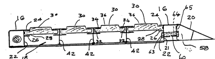
With reference to Figure 1 of the drawings, the reference
numeral 10 refers generally to an elevator platform constructed in
accordance with an embodiment of the present invention. The
elevator 10 includes a frame which is generally identified by the
reference numeral 12 which consists of oppositely disposed first
frame members 14 and oppositely disposed second frame members 16
which are connected to one another and cooperate with one another
to define a rectangular-shaped floor board enclosure 18. A ramp
frame member 20 is attached to one of the second frame members 16,
which forms the front frame member, by means of a nut and bolt
assembly which is generally identified by the numeral 76. As shown
in Figure 3 of the drawings, the first frame members 14 are
U-shaped channel members which have flanges 41 and 43 which
project inwardly of the enclosure 18 from their inner side faces
40 to form a mounting channel 45 which is proportioned to receive
an end of the supporting rails 42 and an end of the second frame
member 16 in a close fitting relationship so as to support the
support rails 42 and frame members 16 in use.
As shown in Figure 2 of the drawings, the second frame
members 16 each have a rectangular cross-sectional configuration
and a side face 22 which is directed inwardly of the enclosure
18. Flanges 24 and 26 project laterally inwardly from the side
faces 22 in a spaced relationship to form a mounting channel 28
therebetween.
A plurality of floor boards 30 are provided, each of
which has oppositely disposed side edges 32 and marginal edge
portions 34 which extend inwardly from the side edges 32 to a
_ 4
2~31~
DS66-2547-196
raised crown portion 36. The floor boards 30 also have oppositely
disposed ends 38 arranged to butt against the inner side faces 40
of the first frame members 14.
A plurality of support rails 42 are provided for the9
purposes of supporting the floor boards. As shown in Figure ~ of
the drawings, each of the support rails 42 has a central rib
portion 46 which has oppositely disposed side faces 44. Flanges
,48 and 50 project outwardly from each side face 44 and serve to
provide mounting channels 52 which as shown in Figure 2 of the
drawings, are proportioned to receive the marginal edge portions
34 of the floor boards in a close-fitting relationship with the
crown portion 40 projecting above the upper face 54.
- As shown in Figure 4 of the drawings, the ends 56 of each
support rail 42 are seated in the mounting channel 45 to the first
.frame members 14 in a close fitting relationship.
As shown in Figures 2 and 5 of the drawings, the first
frame member 16 which forms the front frame member is seated in ..
-the mounting channel 56 of the first frame members 14 in a like
manner to that in which the opposite ends of the support rails 42
are mounted. The frame member 16 is, however, also rigidly
secured to the frame member 16 by means of a mounting bolt
assembly which is generally identiied by the reference numeral
58. As shown in Figure~6, the mounting bolt assembly 58 includes
a tubular sleeve 60 which has a threaded pin 62 projecting
radially outwardly therefrom. A bolt 64 is threaded through the
sleeve 60 and throuqh passages formed in the end wall 65 of the
ramp 20 and throuqh thq side wall 21 of the front frame member
16. The head of the bolt 64 bears against the wall 65 and a nut
;....
,, - .
: ,, " . .... .... . . .,, , . , : . , - , . , , . , , . . . , ....... ~ ,
2~9146
DS66-2547-196
63 is connected to the other end of the bolt 64 and bears against
the side wall 21. This serves to clamp the ramp 20 to the front
frame member 16 and it also serves to position the sleeve 60 so
that the pin 62 (Fig. 5) extends through a passage 67 in the wall
69 of the frame member 14. A nut 71 is threadedly mounted on the
end of the pin 62 and serves to secure the ends Oe the frame
members 16 in the channel 45 of the frame members 14.
The second or back frame member 16 is also a releasable
frame member which is releaseably attached to the first frame
members 14 by mounting means of the type illustrated in Figures 7
and 8 of the drawings which also incorporated the pivot which is
used to connect the platform to the elevator mechanism. The
advantage to constructing the frame so that the frame members 16
can be detached is that this facilitates the mounting of the floor
board 30 which is to be positioned with its marginal edge in the
channel 28 of the detachable frame member 16 and it permits the
platform to be assembled without the need to weld any of the
components to one another.
As shown in Figures 7 and 8 of the drawings, a rod 100
which has centering plates 102 mounted thereon is positioned
within the chamber 104 fonmed within the back frame member 16. A
passage 106 is formed in the web 14a. A rod supporting assembly
108 is provided at each~end of the rod. The rod supporting
assembly 108 comprises a sleeve 110 which has a first plate 112
and a second plate 114 welded thereto in a spaced parallel
relationship. The plate 112 is proportioned to fit in a close
fitting relationship within the channel formed in the frame
members 14 as shown in Figure 8. The inner end portion of the
- 6
2~1~6
DS66-2547-196
tubular member 110 extends through the passage 106 and the other
end portion 116 projects outwardly from the plate 114 and serves
to form the pivot pin on which the platform will pivot when
attached to the elevàtor mechanism. Opposite ends of the rod 100
are threaded to receive mounting nuts 118 which serve to secure
the frame members 14 to the frame member 16.
In the embodiments illustrated in Figures 1 to 8 of the
drawings, the frame members 14 and 16 and the support rails 42 and
the ramp 20 are preferably made for extruded aluminum. The floor
boards 30 are preferably made from wood.
In the embodiment illustrated in Figure 9 of the
drawings, the floor board members 80 are made from extruded
aluminum and include a stiffening rib portion 82 which extends
downwardly from the centre of the width of the floor panel portion
84. The floor panel portion 84 has marginal edge portions 86
which are formed to provide a recessed shoulder 88 from which a
flange 90 projects downwardly and outwardly to a rounded edge
portion 92. The marginal edge portion 86 is proportioned to fit
in a close-fitting relationship within the channel 52 of the
support rail 46 and within the channel 28 of the second frame
members 16 (Fig.2).
The downwardly and outwardly inclined flange portions 90
will tend to be deflected outwardly under the influence of a load
applied to the floor panel portion 84 and this will further serve
to seat the floor board members 80 in the mounting channels of the
support members and frame members.
The width of a typical elevator platform constructed in
accordance with an embodiment of this invention may range from
20~91~
DS66-2547-196
about 57" to 90~ and the front to back depth from the outer side
edges of the frame members 16 may measure from 24" to 36~. The
frame member3 14 and 16 may have a depth of about 2~ with the
combined width of the upper flanges being about 1 1/4~ and the
combined width of the lower flanges 50 being about 1~. The
thickness of the central rib may be about .1~ and the width of. the
lower end portion ~4 may be about .3". The height of the mounting
channel 52 and the mounting channel 28 may be about 1.3". The
wooden floor boards may each measure about 4~ in overall width and
have a thickness of about 1 3/4n.
It will be apparent from the foregoing that the various
components of the frame may be prefabricated to form a kit which
can be easily assembled and as a consequence, it is possible to
ensure that each of the frame members has a length which is equal
to the maximum dimension of any platform which might be required.
When a platform smaller than the maximum size is required, it is
then merely necessary to cut each of the frame members to the
required length and to make corresponding length adjustments to
the support members and frame members. As a result, it is
possible to assemble a platform of any required width and front to
back depth from these standard components.
Various modifications of the present invention will be
apparent to those skilled in the art without departing from the
scope of the invention.