Language selection

Search

Patent 2009209 Summary

Third-party information liability

Some of the information on this Web page has been provided by external sources. The Government of Canada is not responsible for the accuracy, reliability or currency of the information supplied by external sources. Users wishing to rely upon this information should consult directly with the source of the information. Content provided by external sources is not subject to official languages, privacy and accessibility requirements.

Claims and Abstract availability

Any discrepancies in the text and image of the Claims and Abstract are due to differing posting times. Text of the Claims and Abstract are posted:

  • At the time the application is open to public inspection;
  • At the time of issue of the patent (grant).
(12) Patent: (11) CA 2009209
(54) English Title: CLOSURE STRIP
(54) French Title: BAUDE DE FERMETURE
Status: Expired
Bibliographic Data
(52) Canadian Patent Classification (CPC):
  • 220/12
  • 24/81
(51) International Patent Classification (IPC):
  • B65D 77/10 (2006.01)
  • B65D 33/16 (2006.01)
(72) Inventors :
  • HOLMES, JACK H. (United States of America)
(73) Owners :
  • KWIK LOK CORPORATION (United States of America)
(71) Applicants :
(74) Agent: OYEN WIGGS GREEN & MUTALA LLP
(74) Associate agent:
(45) Issued: 1995-12-12
(22) Filed Date: 1990-02-02
(41) Open to Public Inspection: 1990-08-10
Examination requested: 1992-05-15
Availability of licence: N/A
(25) Language of filing: English

Patent Cooperation Treaty (PCT): No

(30) Application Priority Data:
Application No. Country/Territory Date
309,276 United States of America 1989-02-10

Abstracts

English Abstract


A multi-closure strip of generally flat, semirigid
plastic closures which are joined by sets of transversely
spaced connecting material in which the connecting material
is formed between smoothly rounded protrusions, each having
an apex and a wider base. The connecting material is along
a line generally parallel or at a slight angle to the longi-
tudinal axis of the multi-closure strip. A gap is provided
between the transversely spaced sets of closure material so
that, by the application of a lateral force, the connecting
material is separated in tension as one closure moves later-
ally relative to the other.


Claims

Note: Claims are shown in the official language in which they were submitted.


Claims

1. In a multi-closure, end-to-end strip of
semirigid, plastic closures wherein the closures each have a
side-edge, bag-neck access opening joining a bag-neck
receiving opening, said closures being joined together in a
strip by connecting material between the ends of adjacent
closures, the ends of each closure having protrusions
extending parallel to the longitudinal axis of the strip,
the connecting material having two portions separated
transversely by a gap between the ends of adjacent closures,
each portion being defined by the protrusions of the ends of
the closures, the protrusions of the end of one closure
being transversely offset from and logitudinally overlapping
the protrusion of the next adjacent closure, with the
connecting material being along a line generally parallel to
the longitudinal axis of the strip and within the overlap of
the protrusions of adjacent closures, whereby lateral
movement of the endmost closure relative to the next
adjacent closure will fracture the connecting material
between the overlapping protrusions in tension, leaving the
protrusions unconnected.

2. The strip of claim 1, said line of connecting
material being along a line about 15 degrees from the
longitudinal axis of the strip.

3. The strip of claim 1, said protrusions each
being smoothly curved and having a base and an apex, said
connecting material lying approximately midway between the
apex and the base.

4. The strip of claim 2, said protrusions each
being smoothly curved and having a base and an apex, said
connecting material lying approximately midway between the
apex and the base.


5. A multi-closure strip of semirigid, thin
plastic closures, said closures each having an access
opening on a side-edge thereof communicating with a bag-neck
receiving opening, means connecting said closures in said
strip for separation by tensile fracture by movement of the
endmost closure laterally in one direction in the plane of
said closure relative to the longitudinal axis of the strip
and the adjacent closure, wherein said connecting means
includes a set of transversely spaced, smooth protrusions on
each closure, the protrusions of the set extending from a
common end of the closure, the opposed protrusions of each
adjacent closure overlapping in the longitudinal direction
of the strip and being interconnected by connecting material
within the overlap of the protrusions and forming an
elongated gap between adjacent closures, said set of
protrusions of the endmost closure being offset transversely
in the plane of the closures in the direction downstream in
said lateral movement relative to the set of protrusion on
the adjacent closure to which it is connected.

6. The strip of claim 5, said connecting
material lying along a line about 15 degrees from a line
parallel to the longitudinal axis of the strip.

Description

Note: Descriptions are shown in the official language in which they were submitted.


2009209


DescriPtion

CLOSURE STRIP


Field of the Invention
This invention pertains to closures formed of
semirigid, flat, plastic material for holding closed the
necks of flexible bags and to strips of such closures
which can be separated by breaking the connections
between adjacent closures in the strip.
.

Description of the Prior Art
Multi-closure strips of the type shown in
United States Patent Nos. 3,164,249; 3,164,250; and
4,333,566 are well known. These closures are generally
made of flat, semirigid plastic. The closures are
separated, preferably by an automatic machine, by break-
ing the connecting material which interconnects adjacent
closures in the strip after the bag neck to be closed is
pushed into the closure.
occasionally, per the invention as described
in Patent No. 3,164,250, the machine for automatically
applying and separating the closures will not break the
straight connecting material between the closures
cleanly, leaving an undesirable jagged tab protruding
from the edge of the closure. Per the invention as
described in Patent No. 4,333,566, the round connecting
material does break cleanly from both connected
closures, leaving a residue of round pieces of plastic
around the machinery. This has now become objectionable
in some packaging operations because of the possibility
of the plastic pieces getting into the product package
under certain conditions.
It is also neC~cc~ry that the connecting
material in these strips of closures have sufficient
strength such that the closures, when in strip form,

2009209
_ 2

will not prematurely break during handling, particularly
when the closures in the strip are subjected to forces
perpendicular to the plane of the closure. This type of
ben~ing can occur frequently because the strips are
stored in large coils and, during handling, the closures
are subjected to bending in the plane perpendicular to
the plane of the closure.
Thus, two of the desired features of a satis-
factory strip of semirigid plastic closures are that
they be able to be handled and not break prematurely,
and, when separated, will separate cleanly without
leaving a ~agged tab.

Summary of the Invention
It is an object of this invention to provide
an improved multi-closure strip in which the closures,
when machine applied, are broken from the strip, leaving
no residue behind. Through many tests, it has been
shown that the most effective way to separate the
connected closures is by using tensile force.
It is another object of this invention to
provide a multi-closure strip of flat, rigid plastic
closures which can be bent in a direction perpendicular
to the plane of the strip or otherwise handled without
prematurely separating the closures from the strip but
which will break cleanly when separated.
Basically, these objects are obtained by
providing the closures in end-to-end connecting array,
with protrusions ext~n~i~g from the ends of the adjacent
closures. Two sets of protrusions extend from each end
of a closure with the protrusions of each set being
transversely spaced from one another. The confronting
protrusions of adjacent closures are connected together
with common connecting material. The separating junc-
ture of the connecting material between the protrusionsis along a line generally parallel or at a slight angle
to the longitll~inAl axis of the strip of closures. A

2009209


minimal central gap is provided between the transversely
spaced protrusions in each set so that by the applica-
tion of a force lateral to the lengthwise axis of the
closure strip, and in the plane of the flat plane of the
strip, the connecting material is separated by tensile
stress as one closure moves laterally relative to the
other.
In the preferred form of the invention, each
protrusion extends smoothly in a rounded shape having a
wide base and a narrower outer apex to provide the
necessary structure to transfer the separating force to
the connecting material. The connecting material is
approximately midway between the base and the apex of
each protrusion.
Brief Description of the Drawings
Figure 1 is a fragmentary plan view of a
multi-closure strip embodying the principles of the
invention.
Figure 2 is a fragmentary plan view of a
multi-closure strip embodying the principles of the
invention, with a breaking implement shown shifting the
endmost closure laterally relative to the next closure
of the strip.
Figure 3 is an enlarged detail of the closure
strip showing the connecting material positioned between
the protrusions of adjacent closures.

Detailed Description of the Invention
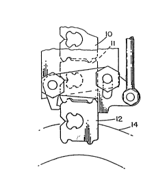
The figures show a portion of a multi-closure
strip of generally flat, semirigid, plastic closures,
with only the endmost closures 10, 11 and 12 being
illustrated. It is understood, however, that these
closures generally come in an elongated strip stored in
a coil, with the axis of the coil being generally right
to left, as shown in Figure 1 of the drawing.

2009209
_ 4

Bags whose necks are to be held closed by the
closures generally travel along line 14 and become
gathered into the bag neck receiving opening 16 of the
closure, as illustrated by the wavy lines 18 in Figure
2.
Each closure has a bag neck receiving opening
16 and a bag access opening 19.
The adjacent closures are interconnected by
interconnecting material 20 between two sets of trans-
versely spaced protrusions 22 and 24, and 26 and 28.Each protrusion is substantially identical and includes
an apex 30 and a wider base 32, with the apex being
rounded as shown in Figure 3. The protrusions are
separated by a gap or punched-out opening 33.
lSAlso as best shown in Figure 3, the connecting
material 20 is along a line 60 generally parallel to the
longitll~in~l axis of the strip. A slight deviation from
actual parallelism of about lS degrees (as shown by the
letter "Xn) has been found to be preferred, although
lesser degrees are also satisfactory.
A closure strip of the type identified is
easily broken by a pusher 40 having a rounded tip 42.
The pusher is moved by a member 44 which causes a link
46 connected to the pusher 40 to pivot about an axis 48.
25As best shown in Figure 2, the lateral motion
of the pusher 40 pushes closure 12 laterally to the
right relative to closure 11. This causes the connect-
ing material to receive a tensile breaking stress since
the protrusions 22 and 24 are pulled away from protru-
sions 26 and 28. It has been found that by producing a
tensile breaking stress, separation will be effected
without leaving any residue. This is to be contrasted
with connecting closures of the type shown, for example,
in United States Patent Nos. 3,164,249 and 3,164,250.
In '249 the fracture is a tensile stress fracture but
the force is applied longit~ ly to the strip. In
'250 the fracture is also tech~ically tensile stress

2009209
_ 5


fracture because the connecting webs pivot around
opposite corners of their rectangular shape at their
connection to the adjacent closure, but the webs that
get separated undesirably fall as residue of rectangular
pieces around the machinery as discussed earlier.
While the preferred embodiment of the inven-
tion has been illustrated and described, and while other
alternatives will be apparent, it should be understood
that other variations will be apparent to one skilled in
the art without departing from the principles herein.
Accordingly, the invention is not to be limited to the
exact configuration illustrated in the drawing.

WD50-lVFl

Representative Drawing
A single figure which represents the drawing illustrating the invention.
Administrative Status

For a clearer understanding of the status of the application/patent presented on this page, the site Disclaimer , as well as the definitions for Patent , Administrative Status , Maintenance Fee  and Payment History  should be consulted.

Administrative Status

Title Date
Forecasted Issue Date 1995-12-12
(22) Filed 1990-02-02
(41) Open to Public Inspection 1990-08-10
Examination Requested 1992-05-15
(45) Issued 1995-12-12
Expired 2010-02-02

Abandonment History

There is no abandonment history.

Payment History

Fee Type Anniversary Year Due Date Amount Paid Paid Date
Application Fee $0.00 1990-02-02
Registration of a document - section 124 $0.00 1990-08-17
Maintenance Fee - Application - New Act 2 1992-02-03 $100.00 1992-01-14
Maintenance Fee - Application - New Act 3 1993-02-02 $100.00 1993-01-26
Maintenance Fee - Application - New Act 4 1994-02-02 $100.00 1994-01-04
Maintenance Fee - Application - New Act 5 1995-02-02 $150.00 1995-01-13
Maintenance Fee - Patent - New Act 6 1996-02-02 $150.00 1996-01-24
Maintenance Fee - Patent - New Act 7 1997-02-03 $150.00 1997-01-31
Maintenance Fee - Patent - New Act 8 1998-02-02 $150.00 1998-01-23
Maintenance Fee - Patent - New Act 9 1999-02-02 $150.00 1999-01-21
Maintenance Fee - Patent - New Act 10 2000-02-02 $200.00 2000-01-20
Maintenance Fee - Patent - New Act 11 2001-02-02 $200.00 2001-01-18
Maintenance Fee - Patent - New Act 12 2002-02-04 $200.00 2002-01-18
Maintenance Fee - Patent - New Act 13 2003-02-03 $200.00 2003-01-20
Maintenance Fee - Patent - New Act 14 2004-02-02 $250.00 2004-01-22
Maintenance Fee - Patent - New Act 15 2005-02-02 $450.00 2005-01-20
Maintenance Fee - Patent - New Act 16 2006-02-02 $450.00 2006-01-30
Maintenance Fee - Patent - New Act 17 2007-02-02 $450.00 2007-01-17
Maintenance Fee - Patent - New Act 18 2008-02-04 $450.00 2008-01-18
Maintenance Fee - Patent - New Act 19 2009-02-02 $450.00 2009-01-19
Owners on Record

Note: Records showing the ownership history in alphabetical order.

Current Owners on Record
KWIK LOK CORPORATION
Past Owners on Record
HOLMES, JACK H.
Past Owners that do not appear in the "Owners on Record" listing will appear in other documentation within the application.
Documents

To view selected files, please enter reCAPTCHA code :


To view images, click a link in the Document Description column. To download the documents, select one or more checkboxes in the first column and then click the "Download Selected in PDF format (Zip Archive)" or the "Download Selected as Single PDF" button.

List of published and non-published patent-specific documents on the CPD .

If you have any difficulty accessing content, you can call the Client Service Centre at 1-866-997-1936 or send them an e-mail at CIPO Client Service Centre.


Document
Description 
Date
(yyyy-mm-dd) 
Number of pages   Size of Image (KB) 
Cover Page 1994-03-02 1 12
Abstract 1994-03-02 1 19
Claims 1994-03-02 2 74
Drawings 1994-03-02 1 19
Description 1994-03-02 5 195
Cover Page 1993-10-15 1 12
Abstract 1993-10-15 1 19
Claims 1993-10-15 2 74
Drawings 1993-10-15 1 19
Description 1993-10-15 5 195
Cover Page 1995-12-12 1 16
Abstract 1995-12-12 1 19
Abstract 1995-12-12 1 20
Description 1995-12-12 5 204
Claims 1995-12-12 2 79
Drawings 1995-12-12 1 20
Representative Drawing 1999-07-30 1 6
Correspondence 2006-02-16 1 17
Fees 1994-04-11 3 108
Assignment 1994-03-17 10 213
PCT Correspondence 1995-09-29 1 34
Correspondence 2006-03-01 1 14
Correspondence 2007-05-09 2 15
Fees 1997-01-31 1 46
Fees 1996-01-24 1 45
Fees 1995-01-13 1 47
Fees 1994-01-04 1 34
Fees 1993-01-26 1 35
Fees 1992-01-14 1 37