Note: Descriptions are shown in the official language in which they were submitted.
2~
FIELD OF 'l'lilS INVEN$ION
This invention relates to method and apparatus
for use in membrane distillation separation particularly,
[but not exclusively,] for desalination of sea water or
brine.
BACRGROUND OF THE INVENTION
The principle of membrane separation is known.
In one previous method of membrane distillation separation,
heated sea water or brine is passed along one side of a
capillary membrane and fresh water coolant is passed along
the opposite side of the capillary membrane. In this
method, water permeates through the membrane and mixes with
the fresh water coolant on ~he oppo ite side of the
membrane. The membrane prevents migration of the salts
contained in the sea water or brine across the membrane.
In such prior membrane distillation desalination
processes, all of the sea water or brine must be heated to
a specified temperature even though only a portion of the
heated water permeates through the membrane. Accordingly,
the energy used in heating the balance of the sea water
or brine is lost giving rise to a source of energy
inefficiency. Furthermore, there is a need to improve the
rate of permeation across the membrane.
_ 3 _ 2~ S~
SUMMARY OF THE INVENTION
A distillation separation membrane is provided
for use in the desalination of sea water or brine. The
distillation separation membrane comprises: a porous
support member of a material selected from the group of
polymers consisting of polyvinyl chloride, polypropylene,
nylon, polystyrene, polycarbonate and polysulphone; and a
hydrophobic separation coating within the interstices of
substantially all of the pores of said porous support
member, which are adjacent the surface of said porous
support member, said separation coating having been formed
dynamically by subjecting the surface of said porous
support member to a membrane forming component for a period
of time sufficient to form a separation coating capable of
distillation separation of salt from water.
A method is provided of forming a distillation
separation membrane which method comprises the dynamic
formation, in situ, of a thin film within the pores of or
on a porous support, of a hydrophobic separation membrane
by passing suitable membrane forming components together
across the support surface and causing the components to
react together at said surface to form said membrane.
A method is also provided for the desalination of
sea water using a membrane as set out above and including
the step of heating said sea water thereby causing
vaporization of said sea water, the vapour thus created
3~32~L
-- 4 --
passing through said distillation separation membrane for
subsequent liquefication.
The invention also provides, in a method of
desalination of sea water by means of membrane
distillation, the use of an electro-conductive separation
membrane having an electro-conductive porous support member
and supplying electric current to said porous support
member to heat said sea water in contact with said
distillation separation membrane thereby causing
vaporization of said sea water, the vapour thus created
passing through said distillation separation membrane for
subsequent liquefication.
BRI13F Dl~SCRIPTION OF THE DRAl~INGS
Fig. l is a diagrammatic view of a known
distillation separation module to which the various aspects
of the present invention may be advantageously applied,
Fig. 2 is a diagrammatic view of a distillation
separation module in accordance with the present invention;
Fig. 3 is a diagrammatic layout of a system for
membrane formation in accordance with the present
invention;
Figs. 4A to 4C illustrate various arrangements of
membrane modules in accordance with the present invention.
Figs. 5A to 5C show further assemblies of
membrane modules according to the present invention.
- 5 - ~ 5~
Fi~. 6 is a perspective view of a membrane module
according to the present invention;
Fig. 7 is a perspective view of a membrane
separation distillation module assembly according to the
present;
Fig. 8 is a further perspective view of a
membrane core according to the present invention;
Fig. 9 is a diagrammatic view of a membrane
separation distillation assembly according to the present
invention;
Fig. lO is a further diagrammatic view of a
membrane core module assembly according to the present
invention;
Fig. ll is a diagrammatic illustration of a
membrane distillation separation apparatus according to the
present invention and incorporating various aspects of the
present invention;
Fig. 12 is a sectional view of an apparatus for
membrane distillation according to the present invention;
Fig. 13 is a schematic view of a membrane
distillation desalination apparatu~ according to the
present invention;
Fig. 14 is a schematic view of a membrane
distillation desalination system incorporating membrane
distillation desalination apparatus according to the
present invention;
- 6 - Zc~ 2~
Fig. 15 is a schematic view of a further membrane
distillation desalination system incorporating membrane
distillation desalination apparatus according to the
present invention; and,
Fig. 16 is a schematic view of a membrane
distillation desalination plant incorporating membrane
distillation desalination apparatus according to the
present invention.
BRIEF DESCRIPTION OF PREFERRED RMRODIMENTS OF TH~ INVENTION
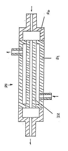
Referring to the drawings, Figure
diagrammatically shows a known membrane distillation
separation ~odule which is generally identified by
reference 20. The module 20 has a tubular membrane 22
mounted within a generally co-axial outer casing 24
provided with end caps 26. In use, elevated temperature
sea water is passed along the interior of the tubular
membrane 22. The term "elevated temperature" is used in
this specification in a relative sense to indicate that the
feedwater has a higher temperature than the coolant water
referred to below. Vapour from the sea water passes
through the walls of the tubular membrane 22 and mingles
with fresh water coolant flowing in the annular space
defined between the exterior of the tubular membrane 6 and
the interior of the outer casing 24.
Referring to Figure 2, a membrane distillation
separation module according to the present invention is
7 2(~ 51
generally identified by reference 28. The module 28 has a
porous support tube 30 running generally centrally there-
along. The porous support tube 30 has a separation
membrane incorporated therewith by means of a dynamic
membrane formation method which is described in more detail
below. The porous support tube 30 is supported within a
heat conductive, thin-walled and waterproof exchange tube
32, to leave a concentric gap 34. The assembly of the
porous support tube 30 and the exchange tube 32 is mounted
within an outer casing 36 which is provided with end caps
38. An annular passage 40 is defined between the exterior
of the exchange tube 32 and the interior of the outer
casing 36.
In use, elevated temperature sea water is
arranged to flow through the porous support tube 30 while
relatively cold sea w~ter is arranged to flow in the
passage 40 between the exchange tube 32 and the outer
casing 36. The elevated temperature sea water within the
porous support tube 30 is subjected to heat to cause the
sea water to vaporize; the water vapour or steam thus
formed passes through the wall of tube 30 into the
concentric gap 34 where it is cooled and liquified by
contact with the inner surface of the heat conductive
exchange tube 32 whose outer surface is in con~act with the
cold sea water.
The efficiency of the prior art device and the
device of the present invention may be increased by
- 8 - ~ 2S~
rendering the tubular membrane (reference 22 in Figure 1)
and the porous support tube (reference 30 in Figure 2)
electro-conductive and by applying an electric current
therealong. This results in a much more localized heating
of the sea water with a consequent energy saving.
Furthermore, by replacing the tubular membrane of the prior
art device with a porous support carryin~ a thin
dynamically formed membrane, as shown by reference 30 in
Figure 3, the flow rate of the permeate through the
membrane may be increased significantly.
The formation of the dynamically formed membrane
and the structure of the membrane modules will now be
discussed in more detail. Referring to Figure 3, the
production of the membrane is shown schematically.
Membrane formation liquids are placed in a container 42.
Suitable liquids include, for example, silico organic
alcohol polymers, organic siloxane, soluble emulsions, or
soluble fluorinated ~polytetrafluoroethylene) polymeric
emulsions. A suitable indicator agent is also added.
When using the invention for membrane distillation
desalination, sodium chloride may be used in a small amount
as the indicator agent. A solvent will be present which
may be water or an organic solvent or a mixture o~ organic
solvents or water. Also present in the container 42 are
substances to cause the deposition of the membrane. In the
case of silico organic-alcohol polymers the membrane
depositing substance is preferably an acidic substance
9 x~ zs
whilst in the case of emulsions an emulsion-breaking agent
is present.
The membrane is formed within a membrane module
44. To form the membrane, a pump 46 is activated to feed
liquid from the container 42 through a heater 48 to the
membrane module 44. At the same time, coolants from a
container 50 are pumped by means of a coolant pump 52
through the ~embrane module 44.
Initially, because there is little or no membrane
present within the pore structure of the porous support
tubes in the membrane module 44, the indicator agent of the
membrane forming liquid will be able to flow through the
porous support tubes (30 in Figure 2) of the membrane
module 44 and may be detected for example by conductometric
means. Gradually however, membrane formation will occur
within the pores of the porous support tube 30 and the flow
of indicator agent through the walls of the support body
will gradually diminish. When the level of transported
indicator agent falls to a pre-determined minimum value,
the pumps 46 and 52 and the heater 48 are switched off and
the membrane module 44 is removed for post-processing.
Such post-processing generally incudes curing by physical
treatment which may include air, room te~perature air or
heating in an oven. Conditions which have been found to be
satisfactory for membrane formation are summarized in the
following chart:
1 0 ~ ;2~ 3~32~o
Conditions for Membrane formation
a. Feed Formula
Membrane formulation materials - 1 to 5000 PPM.
Indicator agents - ratio of molecular
no. and membrane
materials is 1/16 to 1
Additives 0 to 1 molar
Solvent 90 to 100%.
b. Process Conditions
Temperature of feed 30 to 99 deg. C
Time required 20 to 460 minutes
Pressure 0.01 to 5 kg/cm
Flow Speed 5 to 100 cm/min
(Feed flow inside capillary tube membrane)
Coolant Temperature 5 to 80 deg. lower than
that of feed temperature
c. Post Treatment Processinq
Air-blow temperature for membrane lB0 deg. C
Timing for heating
~or not heating) membrane 0.5 to 24 hours.
d Properties of Resultant Membrane
.
Salt recovery 99 to 99.8~
Permeate productivity 45 to 100 litre /day m
11- 2C~ S~
The porous support tube 30 should have a pore size
of from .02-1 micron. Such porous support tubes 30 are
commercially available manufactured from nylon, poly-
propylene, cellulose acetate and cellulose triacetate.
Examples of commercially available support tubes include
those manufactured by Micaon Separations Inc. and sold
under the trade mark Calyx Capsules. Alternatively, porous
support tubes 30 may be manufactured from polysulfone,
polyvinyl chloride, polyvinyl and polyvinyl alcohol. Such
support tubes may be manufactured using known techniques
such as described in "Membrane Science and Technology" Wang
Ying 1986 Second China.
Referring now to Figures 4A-4C, arrangements are
shown wherein a plurality of the porous support tubes 30
having separation membranes on them are bundled together
to form membrane modules of different geometric
configurations. The membrane modules are identified
generally by a reference 53. The membrane modules 53
illustrated in Figure 4A-4C have one or more porous support
tubes 30 within a single support tube casing 51. In these
arrangements, it is preferable that the difference between
the external diameter of the support tube 30 or the bundle
of support tubes 30 and the internal diameter of the
support tube 51 be relatively small so as to maximize the
efficiency of heat exchange.
- 1 2 - 2(~332~j~
A~ shown in Figure 4B, the support tube casing
does not have to be a round tube as shown in Figure 4A,
instead, flat walled tubing 54 may be employed. The
support tube casing 51 or 54 may be of plastics material or
thin corrosion-proof metal. As also shown in figure 4B,
the individual support tubes 30 may be secured together by
means of fine fibres 56 for subsequent insertion into a
support tube support casing. Alternatively, a sheet of
assembled support tubes 30 (Figure 4C) may be rolled up
between sheets of plastic film 70 about a central tube 62.
A sheet of net-like material 60 is placed on the sheet of
plastic film 70 on one of the faces of ~he film opposite
the support tubes 30 and rolled up with the film and tube
assembly. The net-like material 60 is included to provide
a conduit for cooling water adjacent the plastic film 70.
The central tube 62 i5 provided with openings 63 through
the sides thereof to receive permeate from between the
sheets of plastic film 70 which then collects within the
central tube 62.
As may be seen from Figures 5A through 5C, the
support tube casings 51 containing bundles of support tubes
30, may themselves be assembled within the outer casing 36
in a variety of ways. Figures 5A, 5B and 5C correspond
respectively to the arrangements shown in Figures 4A, 4B
and 4C. The diameter of the outer casing 36 shown in
Figures 5A-5C would typically be at least one inch and may
be greater than eight inches. The assembling of the
- 13 - ~ ~a
support tube bundles of Figures 5A through 5C is discussed
in further detail below.
As shown in Figure 6, the assembly of support
tubes within their respective tube support casings 51
may be secured together by providing bonding structures
such as 64. Such bonding structures may be made of epoxy
resin. Each assembled bundle of tube support casings 51
with porous support tubes 30 contained therein is
hereinafter referred to as a membrane core 66. To provide
such a membrane core 66 with suitable rigidity, a
stiffening member such as indicated by reference 68 may be
located therein.
To assemble a membrane core of the type shown in
Figuxe SC, a tube arrangement as illustrated in Figure 4C
may be employed. The individual support tubes 30 having
membranes formed thereon as described above, are placed, in
parallel between two thin plastic membrane sheets 70 as
shown in Figure 4C. The length of the membrane sheets 70
should be such that the sheet extends lO centimetres or
more beyond each end of the support tubes 30. Along the
sides of the plastic sheets 70, a silica gel mixture is
disposed in a one inch to 2 inch thick layer. The
thickness of the silica gel layer should be greater than
the diameter of the porous support tubes 30. As the
plastic sheets are coiled, bonding agents envelop each
porous support tube 30 so as to bond the support tubes 30
and the plastic sheeting 70 together. As the silica gel
- 14 - 2 ~r~ 2 5
extends beyond the ends of the support tubes 30, coiling of
the plastic sheets 70 and support tubes 30 will seal the
ends of the support tubes. The ends of the rolled up
bundle of support tubes however, may be cropped in order to
reopen the support tubes to permit access to the interior
of the support tubes. Alternatively, a sheet of plastic may
be used which is narrower than the length of the support
tubes so that upon rolling, the ends of the tubes will
protrude beyond the silica gel mixture which acts as a
bonding agent. Such an arrangement is shown in Figure 8
where the bonding agent is designated by reference 74.
As shown in Figure 8, the ends of the porous
support tubes 30 may be encased in a further bonding agent
indicated by reference 72. The bonding agent may be epoxy
or, if it is desired to make electrical connection to the
porous support tubes 30 (which will be discussed in more
detail below), a mixture of epoxy and graphite or other
suitable conductive material may be used.
Figure 7 shows a membrane core made up of tube
arrangements as illustrated in Figure 4A. The porous
support tube casings 51 containing porous support tubes 30
are arranged in a generally parallel cylindrical
arrangement. The porous support tubes 30 extend beyond the
ends of the support tube casings 51. The ends of the
support tubes casing 51 are bonded together with a suitable
bonding agent at 74. The ends of the porous support tubes
30 are bonded together by a further bonding agent at 72.
- 15 - 2~
Figures 9 and 10 show membrane separation
distribution modules of the type generally illustrated in
Figure 2. Similar components are indicated by li~e
references. The module 28 shown in Figure 9 corresponds
to the tube arrangement shown in figure 7 whereas the
module 28 shown in Figure 10 corresponds to the tube
arrangement of Figuré 8.
Referring to Figure 9, the membrane GOre 66 is
placed within an outer casing 36 so that the tube support
casings 51 extend the length of outer casing 36. The
membrane core 66 is fluidly sealed to the casing 36 by a
suitable seal, such as an O-ring, at 75 which extends
between the interior of the casing 36 and the bonding agent
74.
The outer casing 36 is provided with tubular
extensiQn portions 37 at either end. The ends of the
porous support tubes 30 extending from the bonding agent 74
are received within the extension portions 37. The outer
ends of the extension portions 37 are provided with end
caps 26. Suitable seals such as an O-ring 77 provide a
seal between the interior portion of the extension 37, the
bonding agent 72 at the ends of the tubes 30 and the end
caps 26.
The operation of the membrane separation
distillation module 28 in Figure 9 will now be described.
Elevated temperature water is introduced as shown by the
arrow at reference 98, flows along the length of the
- 16 ~ 5~
support tubes 30 and is discharged as shown at reference
100 through the opposite end cap 26. Cold water is
. introduced as shown by the arrow at reference 102, flows
around the exterior of the tube support casings 51 and
discharges from the outer casing 36 as shown by the arrow
at reference 104. The water vapour which permeates through
the porous support tubes will cond~nse within the tube
support casings 51 and exit from the tube support casings
between the two bands of bonding agent 72 and 74. This
condensed fresh water permeate will then be discharged from
the membrane distillation separation distillation apparatus
28 as shown by the arrow at reference 106.
The membrane separation distillation module of
Figure 10 will now be described in more detail. The outer
casing 36 contains that portion of the membrane core 66 of
Figure 8 which is covered by the sheet of plastic film 70.
As discussed above in reference to Figure 9, the outer
casing 36 is provided with extensions 37 at either end. O-
ring seals 79 seal between the outer casing 36 and the
extension 37 at either end of the outer casing 36 but do
not seal between the plastic sheet 70 and the interior of
the casing 36. The support tubes 30 which extend beyond
the ends of the plastic sheet 70 are contained wi~hin the
extensions 37. An O-ring 77 seals between the bonding
agent 72 at the ends of the support tubes 30 and the
interior of the extensions 37. The O-ring 77 also
- 17 - ~9~
provides a seal between end caps 26 and the outer ends of
the extensions 37.
In use, elevated temperature sea water is
admitted at reference 98 through the left hand end cap,
flows through the interior of the porous support tubes 30
and is discharged through the opposite end cap at lO0.
Cold water is admitted through the ri~ht hand extension 37
at reference 102, flows between the plastic sheet 70 and
the outer casing 36 to be discharged through the left hand
extension 37 at reference 104. As discussed above in
relation to reference 4C, a net-like material 60 is coiled
up within the plastic sheet 70 and support tube bundle 58
to permit the cold water to circulate over a substantial
portion of the area of the plastic sheets 70. Elevated
temperature sea water permeating through the porous support
tubes 30 will condense between the porous support tubes 30
and the plastic sheets 70. The permeate will eventually
collect within the central tube 62 through the openings 63
in Figure 4C and be discharged through the ends of the
central tube 62 which extend through both of the end caps
26 as indicated by references 106 in Figure lO.
Figure ll shows a further embodiment of a
membrane separation distribution module 28 according to the
present invention. The embodiment of Figure ll differs
from the embodiments of Figures 9 and lO insofar as the
regions of elevated temperature and cold water flow are
Z~ 5~
- 18 -
concerned. The embodiment of Figure 11 uses a singleporous support tube 30 rather than a tube bundle. The
porous support tube 30 has a hydrophobic membrane 80 formed
on its exterior and interior surfaces. This membrane is
both electro-conductive and solar heat absorptive. Within
the porous support tube 30, there is a thin wall tube 82
which is both waterproof and heat conductive. The porous
support tube 30 and thin wall tube 82 are generally
concentrically disposed within an outer casing 36.
In use, elevated temperature sea water introduced
at reference 98, passes along the m~mbrane 80 on the porous
support tube 30 and exits at reference 100. A coolant,
such as cold sea water, is passed within the thin wall tube
82, entering at reference 102 and exiting at reference 104.
In this embodiment, permeate passing through the membrane
80 will collect between the thin wall tube 82 and the
support tube 30 and be discharged at reference 106~ A
connector 108 is provided through the outer casing 36 to
enable the elevated temperature water 104 being discharged
from the membrane separation distillation module 28 to be
further utilized, for example, to be fed into a further
module.
The support tubes 30 in the embodiment of
Figure 11 are preferably electro-conductive and are
connected to a source of electrical power 84. Such
electrical connection may be made by having an electro-
conductive layer of bonding agent, for example epoxy
containing graphite, which acts as a conductor between the
power source 84 and the porous support tubes 30A
Furthermore, it is preferable that the outer casing 36 be
transmittive to solar radiation, that the porous support
tube be solar radiation absorptive and that the module be
arranged so that the support tubes 30 may receive solar
radiation. The effect of the solar radiation is to heat
up the incoming sea water whilst the effect of the electric
current supplied to the porous support tube is to cause
vaporization of sea water in contact therewith.
The formation of electro-conductive and
hydrophobic membranes will now be discussed. A porous
suppor~ tube may be formed by means such as extrusion, for
example, from a plastic material to which has been added
suitable organic and inorganic additives (such as graphite,
crushed carbon, polyethylene glycol and/or dodecane
sulphite) to obtain a porosity of 3Q to 50% and pore
diameters within the porous support tube of from 0.2 to 1
microns. The support tube diameter preferably ranges from
2-6 mm. with a wall thickness of from 10-1,000 microns. A
typical formulation of the porous support tube is:
polypropylene 25-75~ by weight;
graphite or crushed carbon 5-75~ by weight;
polyethylene glycol 10-30~ by weight;
dodecane sodium sulphate 5~25~ by weight and
phthaly dibutyl ester 5 20~ by weight.
20 2~.~''3~
The presence of the graphite or crushed carbon will provide
the poro-.s support tube with the necessary de~ree of
electro-conductivity, thermal conductivity and solar
absorptiveness for use in the present invention.
To produce the membrane within the walls of the
support tube, it is preferred to use the method set out
above in the description of Figure 3 using the following
formula:
1. Silico-organic alcohol (or siloxane
emulsion)liquid solution 1-5000 PPM
Colloidal graphite 0.5-1250 PPM
Polyvinyl Alcohol 0.5-100 PPM
2. Silico-organic alcohol (or siloxane
emulsion) liquid solution 1-5000 PPM
Intrinsic conductive polymeric
polyelectrolyte solution 1-2000 PPM
Polyvinyl Alcohol 0.5-100 PPM
A membrane so formed will be hydrophobic in
nature. The conductivity of the membrane will not increase
even when the membrane is in contact with sea water because
of this hydrophobicity. When using the membrane in
distillation desalination, the sea water salts will not
generally be in contact with the membrane because there
will be a layer of saturated water vapour therebetween.
251
- 21 -
Since this water vapour layer contains little if any salt,
it is relatively non-conductive.
The electrically conductive and thermally -
conductive hydrophobic, porous, membrane containing support
5 so formed possesses the following characteristics
Volume resistivity (~) 102 _ 105
Solar absorptivity (~) 0.7 - 0,9
Surface Tension at 20C. (dyne/cm) 20 - 30
Membrane Thickness (microns) 0.1 - 0.4
Voltage Applied (v) 5 - 35
Salt Recovery (~) 99 - 99.8
Permeate productivity
(litres/day/MZ) 45 - 100
A suitable module according to Figure ll has been
15 produced using components having the following dimensions:
Internal diameter of
membrane tube (mm) 2-6
Thickness of membrane tube
(microns) 10~1000
External diameter of
coolant tube (mm) 1.8-5.8
Thickness of coolant tube
(microns) 2.5-6.5
Internal diameter of the
external shell tube (mm) 2.5-6.5
Wall thickness of the
external shell (microns) lOO 1000
- 2 2 - 2~d~ 25~L
Overall length of the
external shell tube (m) 0.4-20
The entire membrane separation apparatus would
typically combine a series of membrane separation
distribution modules 28 having all of the respective flow
channels of feeds, coolant water and permeate of each
module fluidly connected. In order to increase the length
of the apparatus, a plaiting method may be used wherein
fibre lines are used to plait the individual modules 28
together in a generally parallel arrangement in a single or
a pair of lines. Such a combination is referred to as a
"membrane stack" and is generally identified by reference
86 in Figure 12. The stacks may include 5 to 5,000 or more
individual modules 28. The respective reference numbers
indicating flow of elevated temperature water, coolant
water and permeate are the same as used in Figure 11.
The membrane stack 86 is provided with end caps
88 at either end. The end caps 88 may be sealed to the
ends of the modules 28 by an elastic silica gel after
insertion of the ends of the modules into the end caps.
Membrane stacks such as 88 may be placed on
oblique ground or racks which are coated with solar
reflection paints. The degree of obliqueness of the ground
or racks should be selected so as to correspond to the
latitude of the location in order to maximize the amount of
solar heat absorbed.
23 - Z~`925~
The flow of permeates may be considerably
increased during the membrane distillation desalination
process by creating a partial vacuum in the space adjacent
the fresh water side of the membrane. ln the embodiment of
Figure 11 this would be the space between the thin walled
tube 82 and the porous support tube 30. It has been found
that such reduced pressure tends to bring down the boiling
point at the contact region between the membrane 80 and the
sea water and produce more saturated vapours. Moreover,
such a reduced pressure enables the water vapour or steam
which has penetrated the membrane 80 to leave the pores in
the porous support tube 30 so that the steam does not
condense inside the pores and block the heat exchange
between the cold air and the steam. It is believed that
this method has not been previously used in the process of
membrane distillation desalination and is therefore
regarded as another novel characteristic of the present
invention.
A preferred methocl is illustrated in Figure 13
which shows the use of a venturi vacuum pump. A venturi
vacuum pump 89 is fluidly connected to the permeate
discharge openinq of the membrane separation distillation
module 28 by conduit 91. The venturi vacuum pump 89 has a
venturi tube 90. Permeate which has collected in a tank 92
is pumped by a pump 94 through the venturi tube 90. An
area of reduced pressure is thus created adjacent a venturi
within the venturi tube 90. The conduit 91 is connected to
- 24 - ~ 51.
the area of reduced pressure. Using such an arrangement
satisfactory results have been obtained by using a negative
pressure of from .02 to 0.8 kg/cm2 and an elevated water
temperature of less than 50C. The application of the
vacuum should be gentle in order not to damage the
membrane.
When using a membrane distillation separation
apparatus according to the present invention in tropical
areas, the difference in temperature between deep sea water
(8' deep or more) and surface sea water may be utilized to
reduce energy input required. The coolant may comprise
deep cool sea water and the warmer surface sea water may be
used to contact the membrane to perform the desalina~ion
process more efficiently.
To further minimize energy consumption, during
heating the rate of vaporization should be matched to the
rate of steam penetration through the membrane.
Figure 14 sch~matically illustrates a
membrane distillation separation and salt recovery system
utilizing membrane distillation separation modules 28a and
28b of the type illustrated in Figure 11 arranged in
menlbrane stacks according to Figure 12. A pump llG draws
in surface sea water, in surface sea water, which has an
elevated temperature, and pumps it through a filter 114 and
into the first membrane separation distillation module 28a.
Pump 112 draws in cooler, subsurface sea water and pumps it
through filter 118 into the coolant port of membrane
- 25 - ~3~
distillation separation module 28a. The sea water is
desalinated in the membrane distillation separation module
28a and permeate is withdrawn using a venturi-vacuum pump
89a with the permeate collecting in container 92a. Pump
94a is used to pump permeate through the venturi vacuum
pump 89a to create the vacuum. Current from an electrical
source 84 is applied across the ends of the porous support
tubes within the module 28a to vaporize the elevated
temperature water and cause it to permeate through the
membrane layers on the porous support tubes.
A portion of the coolant water discharging from
the membrane separation distillation module 28a is diverted
through a heat exchanger 120 the function of which will be
discussed in more detail below. The remainder of the
coolant water is further utilized as coolant water through
a second membrane separation distillation module 28b.
The elevated temperature sea water passing
through the first membrane separation distillation module
28a is pumped by pump 118 through the elevated temperature
sea water ports in a second membrane separation
distillation module 28b. It will be appreciated that the
concentration of salt in this elevated temperature water
will have been increased as a result of fresh water
permeate being removed in the first membrane separation
distillation module 28a. The second membrane separation
distillation module 28b removes further water from the
concentrated elevated temperature sea water. The permeate
- 26 - 2C,~ 2~
is drawn from the second membrane separation distillation
module 28b by venturi vacuum pump 89b to collect in
container 92b. Pump 94b is used to pump water from the
container 92b through the second venturi vacuum pump 89b.
Concentrated elevated temperature sea water emanating from
the second membrane separation distillation module 28b
passes through the heat exchanger 120 where it is cooled by
a portion of the coolant emanating from the first membrane
separation distillation module 28a. This cooling of the
concentrated sea water causes a portion of the salts to
come out of solution. The cooled sea water and salt
precipitate is pumped to a centrifuge 122 where they are
centrifugally separated.
Figure 15 shows yet another membrane separation
distillation and salt recovery system. In the system of
Figure 15 a pump 110 draws sea water and pumps it through
a filter 114. A portion of the sea water emanating from
filter 114 is used as elevated temperature sea water. The
balance of the sea water is used as coolant water.
Reference 124 indicates a solar heat exchanger which heats
that portion of the water which is to pass throuqh the
membrane separation distillation modules 28a and 28b. The
water may be further heated, for example by electrical
heaters 126. The heated water passes through a first
membrane separation distillation modllle 28a which also
receives coolant from filter 114. Permeate discharging
from the first membran~ separation distillation module 28a
- 27 - 2~`~3~
will itself have an elevated temperature. The permeate is
therefore passed through a heat exchanger 128 where a
portion of the heat is used to further heat elevated
temperature sea water passing through the solar heat
exchanger 124. A venturi vacuum pump 89a draws the
permeate from the heat exchanger 128 in a manner analogous
to those discussed above. Concentrated elevated temperature
sea water passes from the first membrane separation
distillation module 28a through a further heater 130 and
into a second membrane separation distillation module 28b.
The second membrane separation distillation module 28b also
receives coolant water from the filter 114. Permeate from
the second membrane separation distillation module 28B is
also passed through heat exchanger 128. Concentrated
elevated temperature sea water from the second membrane
separation distillation module 28b is cooled in a heat
exchanger 120 to cause salt to come out of solution. The
salt and the water are separated centrifugally by a
centrifuge 122. Coolant water which has passed through the
first and second membrane sepaxation distillation modules,
28a and 28b respectively, is used as a cooling source for
the heat exchanger 12~.
The system illustrated in Figure 14 uses a
membrane separation distillation module of the type
illustrated in Figures 11 and 12 whereas the system
illustrated in Figure 15 uses membrane separation
28 - 2~3~ 51.
distillation modules of the type illustrated in Figures 9
or 10.
Figure 16 is a schematic for a sea water
desalination and salt production plant. Sea water is drawn
into the plant at 132 by pump 134. Pump 134 passes the sea
water through germicidal equipment 136. The germicidal
equipment 136 inc~udes chlorine equipment 138 and a sodium
hypochlorous evaporator 140. The germicidally treated
water passes through a coarse filtration apparatus 142 and
a precision filtration apparatus 144. The water then
collects in a basin 146 from where it is drawn by pump 148
and passed on to a first membrane desalination distillation
unit 150.
Fresh water leaves the first membrane desal-
ination distillation unit 150 at reference 152, passes
through heat exchangers 154 and 156, through venturi pump
158 to collect in basin 160. A pump 162 pumps water from
the basin 160 through the venturi tube of the venturi pump
158. Pump 162 also pumps water from ~he basin 160 into a
higher basin 164 which acts as a fresh water reservoir.
Coolant water from the first membrane separation
distillation ~odule 150 is discharged at reference 166 ~t
the top of Figure 16.
Concentrated sea water leaves the first membrane
separation distillation module 150 at reference 168, is
heated by heater 170, solar heater 172 and heat exchanger
174. The heated concentrated sea water then passes through
s~
- 29 -
a further heater 176 into a second membrane separation
distillation unit 178.
Fresh water permeate is drawn from the second
membrane distillation separation module 178 as shown by
arrow 180 and is passed through a heat exchanger 182 from
where it passes on to heat exchanger 156 and through the
venturi vacuum pump 158 to collect in the basin 160.
Coolant water is discharged from the second
membrane distillation separation module 178 at reference
184.
Concentrated sea water from the second membrane
separation desalination unit is passed through an
evaporator 186 and the salt and bittern are further
separated at centrifuge 188.
Equipment is also provided to control and monitor
pressure, flow rate and water temperature. Typical
locations for such equipment are indicated by references 5
which indicate temperature controllers, references 6 which
indicate valves, references 7 which indicate pressure
gauges and references 8 which indicate flow meters.
The present invention may be further illustrated
by reference to the following examples.
Example 1
A dime~hoxy siloxane dynamically formed membrane
was produced on a polysulfone porous support body. To do
so, a polysulfone porous capillary tuhe was placed in a
- 30 -
module in accordance with that illustrated in Figure 2.
The size of the pores in the poysulfone body was .25
microns, the interior diameter of the capillary tube was 2
millimetres and had a wall thickness of .12 millimetres.
The module was placed in a membrane forming system as
illustrated in Figure 3. The formula for the dynamically
formed membrane material was as follows:
Dimethylbutane methoxy siloxane
emulsion - 50 PPM
Sodium chloride 20 PPM
Purified water 100~
The pump 46, heat exchanger 48, coolant pump 15
and coolant heat exchanger 96 were turned on for 30
minutes. At this time the feed temperature reached 60C.,
the coolant water was at 25C. and the permeate started to
penetrate the porous support tube. The system was operated
for 60 minutes, at which time a comparison of the
conductivity of the permeate and that of the feed indicated
a separation rate of 80~. 0.01 MCL siloxane was then
added and the operation was continued for another 10
minutes. At this point the pump and heating were stopped,
the module was blown dry and put into an oven to heat
approximately 2 hours at 90C. The module was removed and
cooled and put back into the system which was operated for
an additional hour. At this point, the separation rate of
the membrane was approximately 99%. It was found that the
membrane thus produced when operated under conditions of
- 31 - 2~ Z S~.
partial vacuum could give separation rates as high as 50
L/l:)M2 .
It is to be understood that what has been
described are preferred embodiments of the present
invention and that variations may be possible while staying
within the spirit and scope of the present invention.