Note: Descriptions are shown in the official language in which they were submitted.
~0~ 3
l 53,071
BUS AIR CONDITIONING UNIT
TECHNICAL FIELD
The invention relates in general to bus air
conditioning units, and more specifically to air condi-
tioning units suitable for mounting from the roof of a
vehicle.
BACKGROUND ART
A large market has developed for small busses
which travel at relatively low speeds over shoxt distances,
such as the shuttle busses used at airports between planes,
terminals, car rentaIs, and the Iike. These shuttle busses
are substantially less costly than the large high~ay
busses, and it would be desirable to provide air condi~
tioning units for such busses which are also less costly
than units for the large busses, while maintaining reli-
ability and serviceability.
SUMMARY OF ~HE INVENTION
Briefly, the present invention is a new bus airconditioning unit having a low height dimension, sultable
for roo mounting on shuttle busses. The new bus air
conditioning unit is less costly to manufacture, easier to
service, and lighter in weight than conventional bus air
conditioning units~
Instead of building a frame and mounting refrig-
eration components on the frame, certain of the refrigera-
tion components, such as the condenser, control panel,motor mount and evaporator drain pan, are all integral
83
2 55,071
structural members of the frame, reducing the weight and
cost of the unit. The component layout permits a single
electric motor to drive two evaporator blowers and two
condenser fans, with space for two motors when the voltage
of the bus electrical system re~uires two smaller motors.
The fans and blowers are directly mounted to two shafts,
which are coaxial with the axis of the drive motor.
The unit may be mounted on the front or rear end
of the bus, on or just below the roof line, simply by
selecting the condenser fan blades to either draw air into
a condenser plenum, or to exhaust air from the condenser
plenum. ~efrigeration components which are not mounted
outside the frame, are easily accessed for maintenance,
simply by lifting a cover disposed on the frame. The
components mounted outside the frame and the control panel
are accessible from the end of the bus the unit is mounted
on.
BRIEF DESCRIPTION OF THE DRAWINGS
The invention will become more apparent by
reading the following detailed description in conjunction
with the drawings, which are shown by way of example only,
wherein:
Figure l is a perspective view of a bus air
conditioning unit constructed according to the teachings of
the invention;
Figure 2 is a plan view of the bus air condi-
tioning unit shown in Figure 1;
Figure 3 is an elevational view of the bus air
conditioning unit shown in Figures 1 and 2, taken from the
evaporator side;
.Figure 4 is a partially exploded perspective view
of the rame of the bus air conditioning unit shown in
Figures 1, 2 and 3;
Figure 5 is an elevational view of a shuttle bus
illustrating bus air conditioning units installed on or
just below the roof of the bus, both front and rear, to
33
3 55,071
illustrate that the unit may be mounted at either end of a
bus, and
Figure 6 is a plan view of the bus shown in
Figure 5, illustrating condenser and evaporator air flow
paths for front and rear mounted air conditioning units.
DESCRIPTION OF PREFERRED EMBODIMENTS
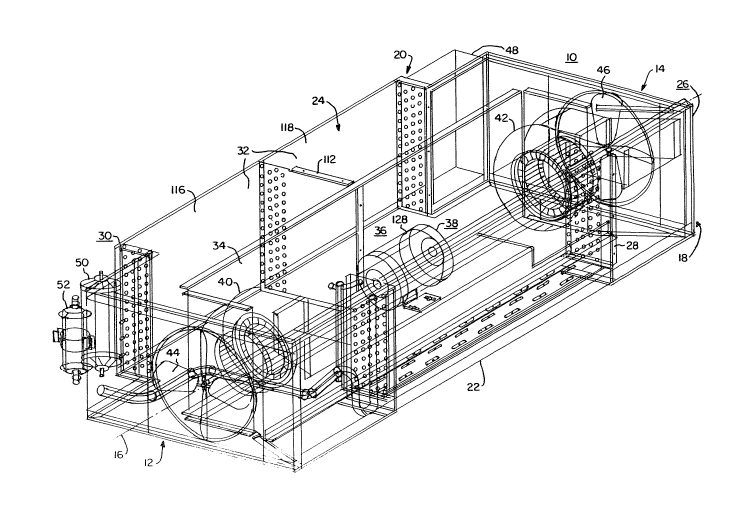
~ eferring now to the drawings, and to Figure 1 in
particular, there is shown a perspective view of a bus air
conditioning unit 10 constructed according to the teachings
of the invention. Figure 2 is a plan view of unit 10, and
Figure 3 is an elevational view of an evaporator side of
the unit 10. Unit 10 has first and second axial ends 12
and 14, respectively, a longitudinal axis 16 which extends
~etween its ends, an evaporator side 18, a condenser side
15 , 20, a bottom 22 and a top 2~. The condenser side 2~ always
faces outwardly from the end of the bus the unit 10 is
installed on, i.e., the condenser side 20 faces outwardly
from elther the front or rear of a hus. The evaporator
side 18 faces a served space inside the bus, and the axiaL
20 ends 12 and 14 are on the sides of the bus. U~it 10 has a
very low profile, about 14.8 inches (37.6 cm) high, permit-
ting the bus to have a rear window, if required, and unit
10 has a total weight of only 336 pounds.
Unit 10 has an elongated metallic frame 26
25 primarily constructed of 0.1 inch (~.254 cm~ thick alumi-
num, as will be hereinafter described in detail. Unit 10
further includes an evaporator coil 28, a condenser coil
30, condenser and evaporator plenums 32 and 34, an air
delivery system 36 which includes electric motor and shaft
30 means 38, first and second evaporator blowers 40 and 42,
respectively, and first and second condenser fans 44 and
46, respectively. A control panel 48, receiver tank 50 and
dehydrator 52 essentially complete the unit 10.
Figure 4 is a partially explode~ perspective view
35 of frame 26. Figure 4 illustrates the parts of frame 26
which are welded together as a unit or weldment 54 in their
normal positions, and the parts which are bolted to the
2~
4 55,071
weldment 54 are illustrated in exploded positions. As
hereinbefore stated, all members of weldment 54 are con-
structed of 0.1 inch (.254 cm) thick aluminum.
More specifically, weldment 54 includes a flat
sheet base member 56 having first and second axial ends 58
and 60, respectively, and first and second lateral sides or
edges 62 and 64, respectively, which extend between the
axial ends 58 and 60. First and second upstanding end
members 66 and 68 are welded to the first and second ends
58 and 60 of base member 54, with end members 66 and 68
defining circular openings 70 and 72, respectively, which
are concentric with longitudinal axis 16.
An upstanding bulkhead 74 is fixed to base member
56, which divides unit 10 into the hereinbefore mentioned
condenser and evaporator plenums 32 and 34, respectively.
Bulkhead 74 has first and second major sides 75 and 77,
respectively, with the first side facing the evaporator
plenum 43, and with the second side facing the condenser
plenv.m 32. Bulkhead 74 includes first, second, third,
fourth and fifth portions 76, 78, 80, 82 and 84, respec-
tively. The first and second portions 76 and 78 start at
the first edge 62 of base member 56, directly adjacent to,
and welded to, upstanding end members 66 and 68, respec-
tively. The first and second portions 76 and 78 then angle
inwardly at an angle of about 54 degrees relative to the
upstanding end members 66 and 68 where they respectively
join the third and fourth portions 80 and 82. The third
and fourth portions 80 and 82 are in spaced parallel
relation with the upstanding end members 66 and 68 respec-
tively, forming fan pockets 86 and 88 adjacent axial ends
58 and 6q, respectively, of base~ member 56. The third and
fourth portions 80 and 82 define openings 90 and 92 coaxial
with axis 16 for mounting shaft bearings 94 and 96, respec-
tively, shown in Figure 2. The remaining upright ends of
the third and fourth portions 80 and 82 are joined by the
fifth portion 84, to complete the evaporator/condense~
bulkhead 74.
8~
55,071
The evaporator side 18 of weldment 54 is complet-
ed by an angle member 98 which is vertically spaced above
edge 62 of base 56, extending between the axial ends 12 and
14 of unit 10. One end of angle member 98 is welded to the
joining ends of upstanding end member 66 and portion 76 of
bulkhead 74, and the remaining end is welded to the joining
ends of upstanding end member 68 and portion 78 of bulkhead
74.
The flat sheet metal of base member 56 is stiff-
ened by welding an electric motor mount 100 and an evapora-
tor drain pan 102 to base member 56. The motor mount 100
is channel shaped with flanged legs. A portion of the
channel configuration is removed adjacent each end, i.e.,-
the bight and a portion of the legs, to provide room for
evaporator blot~ers 40 and 42, while retaining stiffening
support via the integrally extending angle shaped flanged
end portions which remain, such as the integrally extending
angle portions indicated at 104 and 106 on one end of motor
mount 100, and like angle portions at the other end. An
opening 108 for electrical motor leads is centrally provid-
ed when one electric motor is used. With two electric
motors, opening 108 would not be required, and openings
108' would be provided where indicated in phantom.
The condenser side 20 of weldment 56 is not
structurally complete. The condenser side 20 of weldment
56 includes only a short upstanding member 110, ~ich is
preferably a continuation of upstanding end member 66.
Condenser 30 and control panel 48, when bolted to weldment
56, complete the physical integri~y of frame 26.
Condenser 30, in a preferred embodiment of the
invention, is constructed with an intermediate header plate
112 which extends perpendicularly outward from a inner
vertical plane or surface 114. The extension of the
intermediate header plate 112 has a length dimension
selected such that it may be bolted to the bulkhead 74.
This provides additional stiffening to frame 56; and, it
also divides the condenser plenum 32 into first and second
6 55,071
isolated sections 116 and 118, respectively, best shown in
Figures l and 2, to prevent the condenser fans 44 and 46
from bucking one another.
Control panel 48 includes a flat sheet metal back
portion 120 which provides structural support for frame 26,
with all control items being mounted on back portion 120,
.within an enclosing structure 122 bolted to portion 120.
Hot coolant from a radiator of an associated bus may be
connected to the external sides of tubes 124 disposed
through portion 120, with the internal ends of the tubes
124 being connected to a section 126 of evaporator coil 28
used to provide heat for the associated bus when required,
as best shown in Figure 2.
A cover 129 is remo~ably fixed to the top 24 of
~5 unit lO. Simply removincr or pivoting a cosmetic cover, as
shown in Fi~ure 5, and then removing or pivoting the unit
cover 129, provides access to all components, except
receiver 50 and dehydrator 52, which are accessible as soon
as the cosmetic cover is displaced.
Motor and shaft means 38 in a preferred embodi-
ment of the invention includes a single double ended
electric motor 128 mounted on motor mount 100. Motor 128
is coupled to first and second shafts 130 and 132 via
couplings 131 and 133, respectively. Shaft 130, which is
rotatably supported by bearing 94, directly drives evapora-
tor blower 40 and condenser an 44. Shaft 132, which is
journaled for rotation by bearing 96, directly drives
evaporator blower ~2 and condenser fan 46. When the
voltage provided by the electrical system of the associated
shuttle bus is insufficient to drive the connected load,
two electric motors may be pro~vided, each coupled to a
different: one of the shafts 130 and 132.
Figures 5 and 6 are elevational and plan views of
a bus 134 illustrating air flow paths relative to placement
of an air conditioning unit 10 on, or just under the roof
line 135, at the front 136 of bus 134, and on or just under
the roof line 135 at the rear 13~ of bus 134.
7 55,071
When unit 10 is to be placed at the front 136 of
a bus 134, condenser fans 44 and 46 are configured to draw
outside air, indicated by arrows 140, into condenser plenum
sections 116 and 118 through condenser 30, and to exhaust
the heated air, indicated by arrows 142 out the sides of
unit via openings 70 and 72.
When unit 10 is to be placed at the rear 138 of
bus 134, condenser fans 44 and 46 are configured to draw
outside alr, indicated by arrows 144, directly into plenum
sections 116 and 118 via openings 70 and 72, and to force
the air through condenser 30, exhausting heated air,
indicated by arrows 146, rom the rear plane of bus 134,
instead of from the side planes.
In either position of unit 10, the evaporator air
flow is the same, with blowers 40 and 42 being arranged to
draw air, indicated by arrbws 148, from a served space 150,
i.e., the inside of bus 134, and into the evaporator plenum
34 via the evaporator 28. The conditioned air, indicated
by arrows 152, is forced into ducts (not shown) aligned
with the outlets of blowers 40 and 42 for distribution
throughout the served space 150.
Unit 10 is readily serviced from the end of the
bus 134 the unit 10 is associated with, with authorized
personnel gaining access to unit 10 by lifting a cosmetic
cover 154 at the front 136, or a cosmetic cover 156 at the
rear 138 of bus 134.