Note: Descriptions are shown in the official language in which they were submitted.
2009~10
BACXGROUND OF THE INVENTION
The present invention relates to furnishings for
offices and other similar settings, and in particular, to a
mounting arrangement for light fixtures in overhead
cabinets, cases, or the like.
Open office plans are well known in the art, and
generally comprise large, open floor spaces that are
partitioned off into individual workstations. One arrange-
ment for partitioning off the open floor space is to provide
movable partition panels that are configured to receive
hang-on furniture units, such as worksurfaces, overhead
cabinets, shelves, etc. Such partitioning arrangements are
usually known in the office furniture industry as "systems
furniture".
Another alternative arrangement for dividing and
partitioning open office plans provides a plurality of
individual furniture units, each of which is independently
supported on the floor of the open office. The freestanding
furniture units have a modular construction which permits them
~ to be individually arranged and combined in predetermined
configurations to create distinct workstations.
2009~10
1 In both systems furniture and modular furniture
arrangements, light fixtures may be mounted underneath
overhead cabinets, upper cases, or similar storage units to
provide task lighting for the worksurface disposed there-
below. Heretofore, such light fixtures were attached
directly to the bottom of the overhead cabinet by
conventional fasteners, such as threaded screws or the like.
Exemplary task lighting arrangements are disclosed in U.S.
Patent Nos. 4,203,639 and 4,432,044. In such mounting
arrangements, the position of the light fixture in the
cabinet is fixed, and cannot be readily adjusted once it is
fastened in place. Furthermore, the relative size and
weight of the light fixture, as well as the rather difficult
location and orientation of attachment, renders installation
of the light fixture both awkward and time consuming, and
often requires more than one skilled installer.
One aspect of the new ~tructure here described is a
detachable mounting arrangement to quickly and securely
mount light fixtures and the like in overhead cabinets,
without requiring any tools. Front and rear mounting ledges
are located in the lower portion of the cabinet, and are
oriented to face one another. Mounting pins protrude from
one side of the light fixture, and at least one latch
protrudes from an opposite side of thb light fixture. Each
latch includes a spring loaded slide pin, with a thumb tab
to manually shift the slide pin from a normally extended
position to a retracted position. During installation of
the light fixture, the mounting pin is positioned on one of
the ledges, the slide pins are retracted, and the free side
of the light fixture is pivoted upwardly into the bottom of
, 2009410 ~
the cabinet. The slide pins are then released to engage the
opposite mounting ledge, thereby enabling a single installer to
easily and securely mount the light fixture without requiring any
tools whatsoever.
Principal ob~ects of the present disclosure are to
provide a mounting arrangement which is capable of quickly and
securely mounting light fis~es, and the like in overhead
cabinets, without requiring any tools. Spring loaded latch~es
enable a single installQr to easily mount and remove the light
1~ fixture in a con~QniQnt and strain free ~nn~r. Thumb tabs are
provided on the latches to facilitate -ml~lly reciprocating the
same, and are preferably rotatable, 80 that they can be shifted
into a fully retracted position out of sight to prevent
inadvertent release of the latches. The mounting arrang- -nt has
an lnc- licated dQsign with redl~ced manufacturing costs, is
efficiQnt in U8Q, capable of a long operating lif~, and is
particularly well adapted for the propose~ use.
More particularly in accordance with a first aspect of
the invention there is provided, in combination, a furniture
article of the type havinq an ovqrhea~ storage unit, a light
fixture, and a mounting arrangement detachably mounting said light
fixture in said furniture unit under said ovqrhead storage unit,
said mounting arrangement comprising:
a front mounting ledge positioned in a lower
portion of said overhead storage unit, and facing generally
rearwardly;
a rear mounting ledge positioned in the lower
portion of said overhead storage unit, and facing generally
forwardly;
at least two mounting pins fastened to said light
fixture, and protruding generally outward from a first side
thereof; said mounting pins being shaped for abutting
support on one of said front and rear mounting ledges;
-- 3 --
~009410
at least one spring loaded latch mounted in said
light fixture, and including a longitudinally shiftable
slide pin selectively protruding from a second side thereof;
said slide pin having a spring connected therewith to
resiliently retain the same in a fully extended position for
abutting support on the other of said front and rear
mounting ledges, and a tab connected therewith to manually `
shift said slide pin from the fully extended position to a ~;-
fully retracted position to clear the other of said front
and rear mounting ledges, whereby said light fixture is
mounted in said overhead cabinet by positioning said
mounting pins on said one of said front and rear mounting
ledges, grasping said tab and manually shifting said slide .
pin to the fully retracted position, pivoting the second ~ ~-
15 side of said light fixture upwardly into the lower portion -
of said overhead storage unit, and releasing said slide pin,
such that said spring extends said slide pin into the fully
- ~ extended position to engage said other of said front and ~.
rear mounting ledges, and thereby securely mount said light
fixture in said overhead storage unit without requiring any
tools. -
In accordance with a seaon~ aspect of the invention
there. i8 provided, in combination, a furniture article of the type
having an overheA~ storage unit, a light fixture, and a mounting
arrAny ~-~ detachably mounting said light fixture in said
furniture unit under said overhead storage unit, said mounting
arrangement comprising:
a first mounting ledge positioned in a lower
portion of said overhead storage unit, and facing generally
30: laterally inwardly in a first direction;
a second mounting ledge positioned in the lower
portion of said overhead storage unit, and facing generally
- laterally inwardly in a second direction;
- 3a -
.~
20~9~10
. ,, . .~.
at least two mounting means connected with said
light fixture, and extending generally outward from a first
side thereof; said mounting means being shaped for abutting
support on one of said first and second mounting ledges;
at least one latch mounted in said light fixture,
and including a longitudinally shiftable slide selectively
protruding from a second side thereof; said slide having a
biasing means connected therewith to resiliently retain the
same in a fully extended position for abutting support on
the other of said first and second mounting ledges, and a
tab connected therewith to manually shift said slide from
the fully extended position to a fully retracted position to
clear the other of said first and second mounting ledges,
whereby said llght fixture is mounted in said overhead
lS cabinet by positioning said mounting means on said one of
said first and second mounting ledges, grasping said tab and
manually shifting said slide to the fully retracted
position, pivoting the second side of said light fixture
upwardly into the lower portion of said overhead storage
2q unit, and releasing said slide such that said biasing means
extends said slide into the fully extended position to
engage said other of said first and second mounting ledges, :~ .
and thereby securely mount said light fixture in said -~
overhead storage unit wlthout requiring any tools.
.
5 In accordance with a thlrd aspect of the invention there
is provided, a mounting arrangement for detachably mounting a
light fixture or the like in an overhead storage unit of a
furniture article, said mounting arrangement comprising:
a front mounting ledge adapted to be supported in
a lower portion of the overhead storage unit, and facing
generally rearwardly; :
- 3b -
20~9~10
f~
.~
a rear mounting ledge adapted to be supported in
the lower portion of the overhead storage unit, and facing
generally forwardly;
at least two mounting pins adapted to be fastened
to said light flxture, and protrude generally outward from a
first side thereof; said mounting pins being shaped for ;-
abutting support on one of said front and rear mounting ~.
ledges;
at least one spring loaded latch adapted to be
mounted in said light fixture, and including a ~:
longitudinally shiftable slide pin selectively protruding -~
from a second side thereof; said slide pin having a spring
connected therewith to resiliently retain the same in a
fully extended position for abutting support on the other of
lS said front and rear mounting ledges, and a tab connected
therewith to manually shift said slide pin from the fully .
extended position to a fully retracted position to clear the
other of said front and rear mounting ledges, whereby the
light fixture is mounted in the overhead cabinet by
positioning said mounting pins on said one of said front and
rear mounting ledges, grasping said tab and manually -
shifting said slide pin to the fully retracted position,
pivoting the second side of the light fixture upwardly into
the lower portion of the overhead storage unit, and
releasing said slide pin, such that said spring extends said
slide pin into the fully extended position to engage said -~
other of said front and rear mounting ledges, and thereby
securely mount the light fixture in the overhead storage
unit without requiring any tools.
-:3c -
20~9~10
BRIEF DF~cRTPTION OF ~u~ DRAWTNGS
Fig. 1 i8 a perspective view of a light fixture
incorporating a mounting arran~ ~nt embodying the present
invention.
5Fig. 2 i8 another perspective view of the light
fixture.
Fig. 3 is a pQrspective ViQW of the light fixture,
with portions thereof broken away to reveal internal
{~
;
.~
:`
- 3d _
Z~O9~10
1 construction, and shown being installed in an overhead
cabinet.
Fig. 4 is a fragmentary, vertical cross section
view of the light fixture, showing a latch portion thereof
in a normally, fully extended position.
Fig. 4A is a fragmentary, vertical cross-sectional
view of the light fixture, showing the latch in a fully
retracted position.
Fig. 5 is a fragmentary, vertical cross-sectional
view of the overhead cabinet and light fixture, particularly
illustrating installation of the same.
Fig. 5A is a fragmentary, vertical cross-sectional
view of the overhead cabinet and light fixture, particularly
illustrating an intermediate installation position.
Fig. 6 is an enlarged, cross-sectional view of the
latch.
Fig. 6A is an enlarged, cross-sectional view of
the latch, shown installed in the light fixture.
Fig. 7 is a fragmentary, front elevational view of
the overhead cabinet, with a portion thereof broken away to
reveal a tab portion of the latch shown in a fully extended
position for installation.
Fig. 7A is a fragmentary, front elevational view
of the overhead cabinet, with a portion thereof broken away
to reveal the tab portion of the latch, shown in a retracted
safety position.
DETAILED DESCRIPTION OF THE PREFERRED EMBODIMENTS
For purposes of description herein, the terms
"upper," "lower," "right," "left," "rear," "front,"
"vertical," "horizontal," and derivatives thereof shall
relate to the invention as oriented in Fig. 5, and with
--4--
2009~10
1 respect to a seated user. However, it is to be understood
that the invention may assume various alternative orienta-
tions, except where expressly specified to the contrary. It
is also to be understood that the specific devices and
processes illustrated in the attached drawings, and
described in the following specification are simply
exemplary embodiments of the inventive concepts defined in
the appended claims. Hence, specific dimensions and other
physical characteristics relating to the embodiments
disclosed herein are not to be considered as limiting,
unless the claims expressly state otherwise.
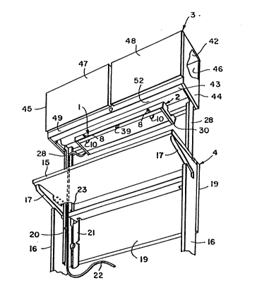
The reference numeral 1 (Figs. 1-4), generally
designates a detachable, quick mounting arrangement
embodying the present invention. Quick mounting arrangement
1 is particularly adapted to removably mount a light fixture
2 in an overhead storage unit, such as the illustrated case
or cabinet 3 of modular furniture unit 4. Front and rear
mounting ledges 5 and 6 (Fig. 5-8) are located in the lower
portion of cabinet 3, and are oriented to face one another.
Two mounting pins 7 protrude from the rear side of light
fixture 2, and at least one latch 8 protrudes from the front
side of light fixture 2. Each latch 8 includes a spring
loaded slide pin 9, with a thumb tab 10 to manually shift
slide pin 9 from a normally fully extended position (Fig. 4)
to a fully retracted position (Fig. 4A). During instal-
lation of light fixture 2, mounting pins 7 are positioned on
rear ledge 6, slide pins 9 are retracted, and the front side
of light fixture 2 is pivoted upwardly into the bottom of
cabinet 3. Slide pins 9 are then released to engage front
ledge 5, so as to quickly and securely mount or support
fixture 2 in cabinet 3, without requiring any tools.
2~9ll ~
With reference to Fig. 3, mounting arrangement 1
is adapted for use in conjunction with furniture arrangements
and the illustrated furniture arrangement comprise~
a plurality of individual furniture units 4, each of which
is independently supported on the floor of an office space,
and is shaped to cooperate with other, related furniture
units 4 to form workstations. The illustrated modular
furniture unit 4 is a straight worksurface unit, comprising
a worksurface panel 15, which is supported at opposite ends
by a pair of intermediate supports 16. Intermediate
supports 16 have an inverted, generally L-shaped side
elevation configuration, with an upper arm 17 thereof
attached to the lower surface of worksurface panel 15, such
that intermediate supports 16 support worksurface panel 15
in a cantilevered fashion. The space disposed underneath
worksurface panel 15 adjacent to intermediate supports 16 is
generally open and unobstructed to facilitate unfettered
task chair movement along the forward edge of worksurface
panel 15.
A back panel 19 (Fig. 3) is attached to the
rearward edges of intermediate supports 16, extends along
the rearward edge of worksurface panel 15, and generally
covers the rearward face or side of modular furniture unit
4. L-shaped brackets 20 with mating removable covers 21 are
attached to the interior sides of intermediate supports 16
and back panel 19, and form a covered wireway through which
wiring, cabling, and the like, such as the illustrated power
cord 22 may be routed. The rear corners 23 of worksurface
panel 15 include arcuate cutouts which mate with the
2~)0~L~Ll~)
1 brackets 20 to route power cord 22 through worksurface panel
15, and upwardly to overhead light fixture 2.
Overhead cabinet 3 (Fig. 3) is mounted on modular
furniture unit 4 above worksurface panel 15 by a pair of
transaction posts 28. Transaction posts 28 have their lower
ends attached to intermediate supports 16 and back panel 19,
and extend vertically upwardly through the cutout rear
corners 23 of worksurface panel 15 in a mutually parallel
relationship. The upper ends of transaction posts 28 are
attached to rearward portions of overhead cabinet 3, so as
to support the cabinet in a cantilevered fashion above
worksurface panel 15. The illustrated transaction posts 28
have a generally L-shaped plan configuration, and are
vertically aligned with brackets 20 to form a continuous
wireway through which power cord 22 may be routed from
overhead cabinet 3 to the bottom of modular furniture unit
4. Removable covers (not shown) are preferably provided for
transaction posts 28 to enclose the same.
The illustrated light fixture 2 (Figs. 1 and 2)
has a generally conventional construction other than
mounting arrangement 1, and includes a chassis 30 with
marginal edges or walls 31-34, and a formed top panel 35.
In illustrated example, light fixture 2 has a formed sheet
metal construction, with a recess defined in the lower
portion thereof in which a pair of opposing electrical
connectors or lamp holders 36 mount a fluorescent light tube
37. Light fixture 2 includes a conventional ballast (not
shown), which is connected with fluorescent tube 37, and
flexible power cord 22 to electrically connect light fixture
2 with a source of electrical power. A toggle switch 39 is
mounted on the lower edge of front face 31, and is connected
2~09410
1 with light fixture 2 to switch fluorescent lighting tube 37
on and off.
The illustrated overhead cabinet 3 (Fig. 3) has a
generally rectangular shape, and includes a top panel 42, a
bottom panel 43, opposite end panels 44 and 45 and a rear
panel 46, which are fixedly interconnected to form chassis
30 of cabinet 3. A channel 49 extends along the front side
of overhead cabinet 3, between end panels 44 and 45, along
the lower portion thereof. Front channel 49 and panels
42-45 frame an opening at the forward side of cabinet 3,
which is selectively closed by a pair of pivotally mounted
closures or doors 47 and 48.
With reference to Fig. 5, the bottom panel 43 of
overhead cabinet 3 is positioned upwardly from the lowermost
edges of front channel 49 and panels 44-46, so as to form a
socket or recess 52 in the lower portion of overhead cabinet
3. A Z-shaped channel 53 is mounted adjacent front channel
49, and extends along the forward edge of overhead cabinet
3. Front channel 53 forms the generally horizontally
disposed front track or ledge 5, which is in the nature of a
rail, and extends generally along the length of overhead
cabinet 3, and faces generally forwardly. A second channel
55 extends substantially continuously along the rearward
lower portion of overhead cabinet 3, adjacent rear panel 46.
Rear channel 55 includes the rear track or ledge 6, which is
also in the nature of a rail, and faces generally forwardly,
opposite front mounting ledge 5. In the illustrated
example, front mounting ledge 5 is positioned adjacent the
lowermost portion of recess 52, whereas rear mounting ledge
6 is positioned adjacent the uppermost portion of recess 52.
--8--
20~3410
1 The length of lighting fixture 2 is preferably
substantially less than the associated length of recess 52,
so as to permit the longitudinal position of light fixture 2
in overhead cabinet 3 to be slidingly adjusted. The
illustrated rear channel 55 includes a plurality of
forwardly protruding tabs or stops 57 which are positioned
to abut mounting pins 7, and thereby positively limit the
longitudinal or side-to-side movement of light fixture 2 in
cabinet 3. Stops 57 may be spaced apart at regular
intervals adjacent the ends of rear mounting ledge 6, so as
to provide a plurality of positive stop positions. When
stops 57 are provided, substantial longitudinal adjustment
of light fixture 2 in cabinet 3 may require removal and
replacement of light fixture 2 in cabinet 3. In like
manner, the width of light fixture 2 is preferably somewhat
less than the width of recess 52, so as to permit fore-to-
aft adjustment of the position of light fixture 2 in
overhead cabinet 3, in the manner described in greater
detail hereinafter.
With reference to Figs. 1 and 2, the illustrated
light fixture 2 includes two mounting pins 7 extending
rearwardly from the rear wall 32 thereof adjacent opposite
ends of light fixture 2. Mounting pins 7 (Fig. 5) are fixed
or stationary, and have a substantially identical construc-
tion. Mounting pins 7 comprise a rigid rod or shaft 60,
having a generally cylindrical shape. The interior end of
each shaft 60 is rigidly attached to the rear wall 32 of
light fixture 2, and is disposed in a substantially
perpendicular relationship therewith. A non-slip tip or
boot 61 is received over the free end of each shaft 60 and
is adapted to frictionally engage rear ledge 6 to retain
_g_
20~9~1~
1 light fixture 2 in its set position within overhead cabinet
3.
In the illustrated example, light fixture 2 (Figs.
1-3) includes two latches 8, which extend forwardly from the
front wall 31 adjacent opposite ends of light fixture 2.
Each latch 8 has a substantially identical construction,
which as illustrated in Fig. 6-7A, includes a generally
cylindrically shaped body or housing 65 in which slide pin 9
is slidingly received and retained. The front end of
housing 65 includes an annularly shaped collar 66 integrally
formed therewith. A pair of snap lock arms 67 are also
integrally formed with housing 65, and extend forwardly
toward collar 66, and include ribbed or sawtoothed free ends
68 which engage light fixture 2, and retain latch 8 therein
in the fashion illustrated in Figs. 4 and 5. The interior
of latch housing 65 includes an annular recess 69 with an
inner collar 70 at one end for purposes to be described in
greater detail hereinafter.
In illustrated example, slide pin 9 is a rigid,
cylindrically shaped rod having an enlarged forward end or
head 78. A closed sleeve or cap 79 is mounted on the free
end of rod 77, and preferably includes an exterior surface
treatment, such as nubbing, knurling or the like for non-
slide contact with front mounting ledge 5. The illustrated
cap 79 has an arcuately shaped free end, which may also be
knurled or otherwise surface finished for frictional
abutment with the adjacent surface of front channel 53. A
coil spring 80 is positioned around slide pin 9 within the
interior 69 of latch housing 65, and extends between collar
70 and the interior end of cap 79 to resiliently urge slide
pin 9 into a normally fully extended position. In one
--10--
20(:~9410
1 working embodiment of the present invention, coil spring 80
has a resilient force of approximately 8-10 pounds, to
facilitate easy manual shifting of slide pin 9 between the
extended and retracted positions, while assuring automatic
movement to the normally extended position. Tab 10 is
fixedly attached to the forward end of slide pin 9, just
forward of head 78, such that both tab 10 and slide pin 9
translate and rotate together. The upper end 83 of tab 10
(as oriented in Fig. 7) is rounded in a configuration
substantially identical with housing collar 66. The free
end 84 of tab 10 has a substantially rectangular plan
configuration with an inward inset 85. As illustrated in
Figs. 6-7A, tab 10 is rotatable for angular displacement in
either a clockwise or counterclockwise direction between the
exposed or extended position illustrated in Fig. 7, wherein
the free end 84 of tab 10 protrudes outwardly from the
bottom of cabinet 3 to access and grasp the same, and the
hidden or retracted position illustrated in Fig. 7A, wherein
the free end 84 of tab 10 is withdrawn out of sight or
hidden within cabinet 3 and light fixture 2 to prevent
inadvertently releasing latch 8. In the present example,
tab 10 and slide pin 9 rotate as a unit between the extended
and retracted positions.
In operation, light fixture 2 is installed in
overhead cabinet 3 in the following manner. Mounting pins 7
protruding from the rear wall 32 of light fixture 2 are
first positioned on rear mounting ledge 6. The installer
then grasps or engages the tabs 10 of each latch 8, and
pushes the same rearwardly, so as to shift slide pins 9 to
their fully retracted position, as shown by the broken lines
in Fig. 5. With slide pins 9 fully retracted, the forward
--11--
20~9410
1 wall 31 of light fixture 2 is then rotated or pivoted
upwardly into the bottom recess 52 of overhead cabinet 3.
With slide pins 9 in the fully retracted position, the free
ends of slide pins 9 clear the front lip of front channel
53, as shown in Fig. 5A. Once slide pins 9 are disposed
above front mounting ledge 5, the installer releases tabs
10, such that coil springs 80 automatically shift slide pins
9 to their fully extended position to abuttingly engage
front mounting ledge 54. Mounting pins 7 and latch pins 9
thereby quickly and securely capture light fixture 2 within
overhead cabinet 3, without requiring any tools. The
installer then pivots or rotates each tab 10 approximately
9oo either to the right or to the left into the retracted
position within light fixture 2, as shown in Fig. 7A, so as
to prevent tab 10 from being inadvertently hit or otherwise
engaged in a manner that might prematurely or inadvertently
release latch 8. Power cord 22, which is preferably readily
flexible, is routed from light fixture 2 down through the
wireway formed by brackets 28 and 20, and plugged into a
nearby power tap (not shown). The flexibility of power cord
22 also permits light fixture 2 to be easily pivoted up into
the bottom recess 52 of overhead cabinet 3.
To remove light fixture 2 from overhead cabinet 1,
the installer first rotates tabs 10 downwardly into the
extended position illustrated in Fig. 7, and then repeats
the above-described steps in reverse order. A tool (not
shown) may be used to hook over tabs 10, and rotate the same
downwardly into the extended position.
Mounting arrangement 1 is capable of quickly and
securely mounting light fixture 2 in overhead cabinet 3
without any tools whatsoever. The spring loaded latches 8
-12-
20094~0
permit a single installer to removably install light fixture
2 without unnecessary strain. The pivoting tabs 10 on
latches 8 provide a unique safety feature which prevents
inadvertently releasing latches 8.
In the foregoing description, it will be readily
appreciated by those skilled in the art that modifications
may be made to the invention without departing from the
concepts disclosed herein. Such modifications are to be
considered as included in the following claims, unless these
claims, by their language expressly state otherwise.
-13-