Note: Descriptions are shown in the official language in which they were submitted.
-- 1 --
T 597.0
~TACUUM DTSTILLATION DEVICE
The present invention relates to a vacuum
distillation device comprising a vacuum distillation
column having a column inlet, a bottom outlet and a top
outlet, a furnace provided with a heat-exchange tube
having a tube inlet and a tube outlet, and a connecting
conduit provided with an inlet end connected to the
tube outlet and an outlet end which is in fluid
communication with the column inlet.
Such a vacuum distillation device is used to
ap fractionate a hydrocarbon-containing feed. The feed is
sometimes referred to as long residue. During normal
operation the absolute pressure in the vacuum
distillation column is maintained between 650 and 5 200
Pa. Liquid feed passing through the heat-exchange tube
in the furnace is partly vaporized and the partly
vaporized feed is supplied through the connecting
conduit to the column inlet at 2~ temperature o.~ between
380 and 425 °C.
It is an object of the present invention to provide
2o a vacuum distillation device which allows vaporization
of a major part of the feed upstream the column inlet.
To this end the vacuum distillation device
according to the invention comprises a vacuum
distillation column having a column inlet, a bottom
outlet and a top outlet, a furnace provided with a
heat-exchange tube having a tube inlet and a tube
outlet, and a connecting conduit provided with an inlet
end connected to the tube outlet and an outlet end.
which is in fluid communication with the column inlet,
30 wherein the inner diameter of the heat--exchange tubs
CA 02009564 1999-09-03
- 2 -
increases along the length of the heat-exchange tube to
w between 2.4 and 3 times the inner diameter of the tube
inlet, and wherein the inner diameter of the connecting
_; _
conduit gradually increases along the length of the
connecting conduit to between 2.5~and 5.4 times the
inner diameter of the tube outlet.
During normal operation of the vacuum distillation
,. device according to the invention only less than 50% by
weight of the feed is vaporized in the heat-exchange
tube in the furnace and more feed is vaporized in the
connecting conduit, so that at the outlet end of the
connecting conduit the feed comprises about 0.9 kg
vapour/kg feed.
To be able to reduce vaporizing during normal
~5 operation in the heat-exchange tube and to control
the velocity of the fluid in the end part of the heat-
exchange tube at 95% of the length of the heat-exchange
tube its inner diameter is between 1.0 and 1.6 times
the inner diameter of the tube inlet of the heat-
exchange tube, and at 98% of the length of the heat-
exchange tube its inner diameter is between 1.7 and 2.3
times the inner diameter of the tube inlet.
Suitably at a quarter of the length of the
connecting conduit its inner diameter is between 1.0
and 1.8 times the inner diameter of the tube outlet of
the heat-exchange tube, at half of the length of the
connecting conduit its inner diameter is between 1.3
and 2.8 times the inner diameter of the tube outlet,
and at a three quarter of the length of the connecting
conduit its inner diameter is between 1.7 and 4.5 times
the inner diameter of the tube outlet.
The outlet end of the connecting conduit can be
directly connected to the inlet of the distillation
column. In an alternative embodiment, the vacuum
distillation device further comprises a transfer
conduit extending between the outlet end of the
connecting conduit and the column inlet, which transfer
conduit has an inner diameter which is between 0.7 and
5.7 times the inner diameter of the autlet end of the
connecting conduit.
The present invention gill now be described by way
of example in more detail with reference to the
accompanying drawings, wherein
Figure 1 shows schematically a partial cross
7o section of the vacuum distillation device according to
the invention:
Figure 2 shows a top view of an alternative
construction of the vacuum distillation device
according to the invention; and
Figure 3 shows section III-III of Figure 2 drawn to
a scale larger than the scale of Figure 2.
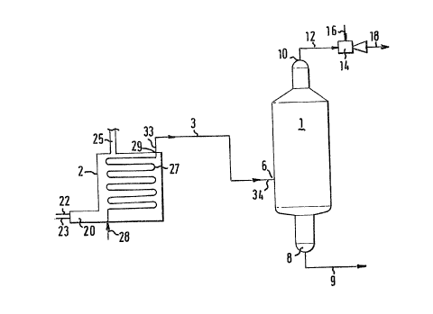
Reference is made to Figure 1. The vacuum
distillation device comprises a vacuum distillation
column 2, a furnace 2 and a connecting conduit 3.
2o The vacuum distillation column 1 is provided with a
column inlet 6, a bottom outlet 8 having a bottom
outlet conduit 9 connected thereto, and a top outlet
10. The top outlet 10 is connected by conduit 12 to a
steam ejector 14 which is provided with a steam inlet
25 conduit 16 and an outlet conduit 18. The vacuum
distillation column 1 is further provided with suitable
internals and draw-off means (not shown).
The furnace 2 is provided with a burner 20 having a
fuel supply conduit 22 and an oxidant supply conduit
30 23, with a flue gas outlet conduit 2~ and with a heat-
exchange tube 27 having a tube inlet 28 and a tube
outlet 29.
The connecting conduit 3 is provided with an inlet
end 33 and an outlet end 39t the inlet end 33 is
- 4 -
connected to the tube outlet 29 and the outlet end 34
is directly connected to the column inlet 6.
The inner diameter of the heat-exchange tube 27
increases along the length of the heat-exchange tube 27
(in the direction of fluid flow) to between 2.4 and 3
times the inner diameter of the tube inlet 28, and the
inner diameter of the connecting conduit 3 gradually
increases along the length of the connecting conduit
(in the direction of fluid flow) to between 2.5 and 5.4
70 times the inner diameter of the tube outlet 29.
The inner diameter of the tube inlet 28 of the
heat-exchange tube 27 is between 0.06 and 0.1 m, the
length of the heat-exchange tube 27 is between 600 and
850 m, and the length of the connecting conduit 3 is
~5 between 50 and 70 m. v
During normal operation the steam ejector 14 is
operated to maintain a subatmospheric pressure in the
vacuum distillation column 1 by supplying steam through
the steam inlet conduit 16 to the steam ejector 1.4.
2o Fuel and oxidant are supplied to the burner 20 of the
furnace 2 to heat liquid feed supplied through tube
inlet 28 and flue gas is removed frpm the furnace
through the flue gas outlet conduit 25.
In the heat-exchange tube 27 the feed is partly
vaporized, thus in the heat-exchange tube 27 there is
always a liqu3,d fraction present; this liquid fraction
ensures a good heat transfer between the inner surface
of the heat-exchange tube 27 and the feed flowing
through the heat-exchange tube 27. ~n effect of the
3p improved heat transfer is that the number of hot spots
on the inner surface of wall of the heat-exchange tube
27 is reduced, so that the number of places at which
liquid feed can be transformed to coke is reduced and
thus the amount of fouling is reduced.
-~ 5 -
As the inner diameter of the connecting conduit 3
gradually increases, the liquid fraction of the feed is
allowed to vaporize in the connecting conduit 3, so
that a sufficiently large amount of the feed is
vaporized.
Reference is now made to Figures 2 and 3. The
vacuum distillation device comprises vacuum
distillation coluann 1, two furnaces 2 and 2', and two
connecting conduits 3 and 3°.
The vacuum distillation column 1 is provided with
column inlet 6, a bottom outlet (not shown) with a
bottom outlet conduit (not shown) connected thereto,
and a top outlet (not shown). The top outlet is
connected to a steam ejector (not shown). The vacuum
~5 distillation column 1 is further provided with suitable
internals (not shown)
The furnace 2 is provided with a burner (not shown)
having a fuel supply conduit (not shown) and an oxidant
supply conduit (not shown), a flue gas outlet conduit
2p, (not shown) and with heat-exchange tube 27 having tube
inlet 28 and tube outlet 29. The furnace 2' is provided
with a burner (not shown) having a fuel supply conduit
(not shown) and an oxidant supply conduit (not shown),
a flue gas outlet conduit (not shown) and with heat-
~5 exchange tube 27' having tube inlet 28' and tube outlet
29°. The heat-exchange tubes 2'7 and 27' have the same
dimensions.
The connecting conduit 3 is provided with inlet end
33 and outlet end 34; the inlet end 33 is connected to
3o the tube outlet 29 and the outlet end 34 is in fluid
communication with the column inlet 6 via transfer
conduit ~0. The connecting conduit 3' is provided with
inlet end 33' connected to the tube outlet 29' and
outlet end 34' which is in fluid communication with the
35 column inlet 6 via transfer conduit 40. The transfer
~n.~~~-
_~_
conduit 40 rests on support 42. The connecting conduits
3 and 3' have the same dimensions.
The inner diameters of the heat-exchange tubes 27
and 27' increase along the length of the heat-exchange
tubes 27 and 27' to between 2.4 and 3 times the inner
diameter of the tube inlets 28 and 28°, and the inner
diameter of the connecting conduits 3 and 3' gradually
increase along the length of the connecting conduits to
between 2.5 and 5.4 times the inner diameter of the
1o tube outlets 2g and 29'.
The inner diameter of the tube inlets 28 and 28' of
the heat-exchange tubes 27 and 2?' is between 0.06 and
0.10 m, the length of the heat-exchange tubes 27 and
27' is between 5 200 and 6 200 m, and the length of the
connecting conduits 3 and 3' is between 200 and 280 m.
The inner diameter of the transfer conduit 40 is
between 2.7 and 5.7 times the inner diameter of the
outlet end 34 of the connecting conduit 3, and the
length of the transfer conduit 40 is between 25 and
35 m.
During normal operation a subatmospheric pressure
is maintained in the vacuum distillation column 1. Fuel
and oxidant are supplied to the burners of the furnaces
2 and 2' to heat liquid feed supplied through tube
inlets 28 and 28' and flue gas is removed from the
furnaces through the flue gas outlet conduits (not
shown).
xn the heat-exchange tubes 27 and 27' the feed is
partly vaporized, thus in the heat-exchange tubes 27
3o and 27' there is always a liquid fraction present, this
liquid fraction ensures a good heat transfer between
the inner surface of the heat-exchange tubes 27 and 27'
and the feed flowing through the heat-exchange tubes 27
and 27'.
_7_
As the inner diameters of the connecting conduits 3
and 3° gradually increase, the liquid fraction of the
feed is allowed to vaporize in the connecting conduits
3 and 3'.
As observed with reference to ~'igure 1 the good
heat transfer in the heat-exchange tubes in the
furnaces reduces fouling of the inner surface of the
heat-exchange tube.
Consequently more heat can be supplied per unit of
1o time to the feed in the heat-exchange tube; this allows
either to heat the feed to a higher temperature or to
increase the thraughput for the same temperature.