Note: Descriptions are shown in the official language in which they were submitted.
-- ' 21~96~5
FIELD OF THE INVENTION
This invention relates to lift and propulsion
systems for aircraft, and more particularly to a thrust
deflector for vertical and short take-off and landing
aircraft.
BACKGROUND OF THE INVENTION
The term "VSTOL aircraft" is used herein to refer
to both vertical take-off and landing aircraft and short
take-off and landing aircraft. It is known in the art of
VSTOL aircraft to deflect thrust from the engines of the
aircraft downwardly for take-off or landing. Typical
methods for deflecting thrust from the engines include
deflector blades, rotatable engine nozzles, and rotating the
entire power unit.
Typical VSTOL aircraft, particularly those capable
of attaining high speeds, use a combustion engine which acts
as a pressurized gas generator which generates pressurized
gas for propelling the aircraft. A problem faced by VSTOL
aircraft is that the temperature of the pressurized gas is
quite high, typically in the range of 1,000 F and higher,
and the pressure is also considerable. When the pressurized
~,
- 2 - 2~9635
,
gas is directed downwardly, the high temperature and
pressure tends to melt tarmac, erode concrete and even heat
metal plates below the aircraft to unacceptably high
temperatures. The result is that operation of VSTOL
aircraft is restricted, and take-off or landing must often
be performed with some forward movement to reduce the
damage.
SUMMARY OF THE INVENTION
According to the present invention there is
provided a thrust vectoring structure for a VSTOL aircraft
having a pressurized gas generator and at least one
generally rearwardly facing outlet fluidly communicating
with the pressurized gas generator and through which the
pressurized gas is discharged to provide thrust for the
aircraft and in which the outlet has an opening defined by a
top, a bottom and sides extending between the top and the
bottom, the top and bottom having respective top and bottom
edges toward the rear of the aircraft and the top extending
rearwardly of the bottom. The thrust vectoring structure has
at least one generally horizontal divider extending between
the sides of the opening. The divider has a forwardly
facing front edge and a rearwardly facing rear edge. The
thrust vectoring structure further has a plurality of front
2(~96~5
and rear flaps. The front flaps are mounted adjacent the top
and front edges of the opening of the outlet. The rear
flaps are mounted adjacent the rear and bottom edges. Each
of the flaps has a leading edge opposite a trailing edge and
is rotatable about an axis adjacent and generally parallel
to the leading edge. The front and rear flaps are mounted
with the leading edges adjacent respective of the top,
front, rear and bottom edges. The flaps are rotatable from
a horizontal thrust position in which the respective
trailing edges of the flaps extend generally rearwardly from
the leading edges to a vertical thrust position in which the
respective trailing edges of the flaps extend generally
downwardly from the leading edges. In the horizontal
position the trailing edge of each of the rear flaps extends
rearwardly from the leading edge of the front flap
immediately above it whereby a generally horizontal thrust
nozzle is defined therebetween. In the vertical position
the trailing edge of each of the front flaps depends below
the leading edge of the rear flap immediately therebelow
whereby a generally vertical thrust nozzle is defined
therebetween. Each of the dividers and the flaps mounted
adjacent thereto define a spacing channel below each of the
dividers, the spacing channels are interspersed between the
vertical thrust nozzles.
-_ -- 4
Z(~39635
BRIEF DESCRIPTION OF THE DRAWINGS
For a better understanding of the present
invention, and to show more clearly how it may be carried
into effect, reference will now be made by way of example to
the accompanying drawings, in which:
Pig. 1 is a cross sectional view through a thrust
vectoring structure according to the present
invention showing the structure in its vertical
0
thrust position with the leading faces of the
front flaps generally parallel to the trailing
faces of the rear flaps;
Fig. 2 shows the thrust vectoring structure of
Fig. 1 with the flaps rotated so that the leading
5
faces of the front flaps diverge from the trailing
faces of the opposing rear flaps;
Fig. 3 shows the thrust vectoring structure of
Fig. 1 with the flaps rotated approximately
mid-way between the horizontal and vertical
0
positlon;
Fig. 4 shows the thrust vectoring structure of
Fig. 1 with the flaps rotated to a horizontal
position with the leading faces of the front flaps
generally parallel to the trailing faces of the
5
rear flaps;
Fig. 5 shows the thrust vectoring structure of
-
Z~9635
Fig. 1 with the flaps in a horizontal position
with the leading faces of the front flaps and the
trailing faces of the rear flaps diverging to form
divergent thrust nozzles;
Fig. 6 shows an alternate embodiment of a thrust
vectoring structure according to the present
invention wherein the top of the outlet is
rotatable away from the bottom;
Fig. 7 is a diagramatic side view of a VSTOL
aircraft showing the general layout of various
components;
Fig. 8 shows the thrust vectoring structure of
Fig. 1 with the flaps rotated so that the leading
faces of the front flaps converge with the
trailing faces of the opposing rear flaps; and,
Fig. 9 shows the thrust vectoring structure of
Fig. 1 with the flaps in a horizontal position
with the leading faces of the front flaps and the
trailing faces of the rear flaps converging to
form convergent thrust nozzles.
Fig. 10 is a diagramatic sectional view, along the
center line of the fuselage of a VSTOL aircraft
having a "pod and boom" type of fuselage and
incorporating a thrust vectoring structure
according to the present invention.
Z~)~9635
DETAILED DESCRIPTION OF THE INV~llON
The decay of temperature and pressure of a jet of
hot air being discharged from an engine nozzle arises from
the mixing of the jet with ambient air surounding the jet. A
S small diameter jet decays much more rapidly than a large
diameter jet in the same physical distance. The thrust
vectoring structure of the present invention divides the
large jet emanating from the aircraft engine into a number
of smaller jets. The smaller jets are spaced apart in the
vertical direction to promote their mixing with ambient air
resulting in considerably more rapid temperature and
pressure decay than that of the large jet.
First referring to Fig. 7, the outline of a
portion of the fuselage 10 of an aircraft is shown in dashed
lines. The fuselage has a front toward the left of Fig. 1
and a rear toward the right of Fig. 1 "forwardly" and
"rearwardly" are used to indicate "toward the front" and
"toward the rear" respectively. The aircraft has an engine
12 which acts as a pressurized gas generator for generating
pressurized gas by the combustion of fuel. Pressurized gas
leaves the engine 12 through the passage 14. A portion, or
all, of the pressurized gas is discharged from a rearward
facing outlet through opening 16 at the rearward end of the
fuselage 10. The thrust vectoring structure of the present
invention can be mounted across the opening 16 of the
2C~1~9635
outlet. In other aircraft fuselage designs, such as
aircraft having twin engine nacelles, one on either side of
the fuselage, the vectoring structure could be located in
the outlets at the rear of the engine nacelles. Similarly,
for aircraft having a pod and boom type of fuselage, the
vectoring structure can be located in the outlet at the rear
of the pod. This latter arrangement is shown in Fig. 10.
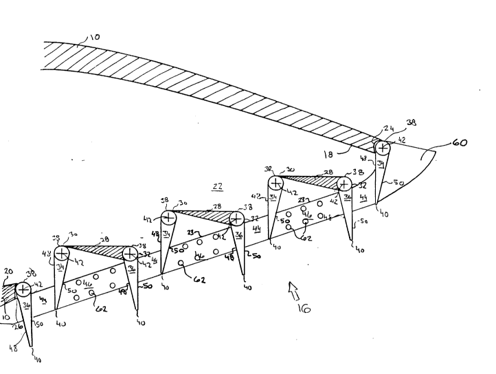
Referring next to Figs. 1 through 5, the rearward
facing outlet is shown in detail. The outlet has an opening
16 defined by a top 18, a bottom 20 and opposed sides
extending between the top 18 and the bottom 20. One such
side is shown at 22 facing in the plane of Figs. 1 through
5. The top has a top edge 24 and the bottom has a bottom
edge 26. The top edge extends rearwardly of the bottom edge.
The rearward edge of the opening is shown at reference 23.
Horizontal dividers 28 extend across the opening
between the sides 22. It will be apparent from Fig. 2 that
the dividers 28 are generally parallel and are arranged in a
generally stepwise configuration. The dividers have a
forwardly facing front edge 30 and a rearwardly facing rear
edge 32. The front edge 30 of the lower most divider is
rearward of and above the bottom edge 26. The front edges 30
of the upper two dividers 28 are above and rearward of the
rear edges 32 of the respective dividers immediately below
them. The rear edge 32 of the uppermost divider 28 is
~ 8 - Z~635
forward of the top edge 24.
Front flaps 34 are mounted adjacent the front
edges 30 of the dividers and the top edge 24 of the opening
16 of the outlet. Rear flaps 36 are mounted adjacent the
rear edges 32 of the dividers 28 and the bottom edge 26 of
the opening 16 of the outlet. Each of the flaps has a
leading edge 38 opposite a trailing edge 40.
The front and rear flaps, 34 and 36 respectively,
are mounted so as to be rotatable about respective axes 42,
generally parallel to the leading edges 38. In this manner,
the rotational axis 42 of each of the front flaps 34 is
rearward of and above the rotational axis 42 of one of the
rear flaps 36.
Figs. 1 through 5, 8 and 9 show the front flaps 34
and rear flaps 36 rotated through a variety of positions.
Mounting the flaps so that they are rotatable about
respective axes 42 may be achieved in various ways, such as
having a shaft extending from either end of the flap and
generally co-axial with the rotational axis. Each such
shaft can be journalled into a bearing having a rotational
axis coincident with the rotational axis 42. Movement of
2(~0963~;
the flaps can be effected by various means such as gear and
sprocket drives, hydraulic cylinders with levers, screw
drives with levers having screw followers, etc.
In Fig. 1 the flaps are shown as being in a
vertical position where the trailing edges 40 of the front
flaps 34 project below the leading edges 38 of the rear flap
36 immediately below it. In this manner a generally
vertical thrust nozzle 44 is defined between adjacent flaps.
Each of the dividers 28 along with the front flap 34 and
rear flap 36 mounted adjacent thereto defines a spacing
channel 46 below each of the dividers. As can be seen from
Fig. 1, a spacing channel 46 is interspersed between each of
the vertical thrust nozzles 44. In this manner, the
pressurized gas being discharged from the outlet 16 is
divided into a number of smaller segmented jets. In order
to ensure that the pressurized gas is not discharged
laterally from the nozzles 44, end plates 60 are provided
adjacent the ends of the flaps so as to extend accross the
ends of the nozzles 40. To ensure air entry into the ends of
the spacing channels 46, holes 62 are provided through the
end plates 60 into the ends of the spacing channels 46. The
front and rear flaps, 34 and 36 respectively, each have a
leading face 48 facing forwardly in Fig. 1, and a trailing
face 50 which faces rearwardly in Fig. 1. In the
-- 10 --
` _ Z(~9635
orientation shown in Fig. 1, the leading faces 48 of the
front flaps 34 are generally parallel to the trailing faces
50 of the rear flap 36 on the opposite side of the vertical
thrust nozzle 44. In this position, thrust resulting from
discharge of pressurized gas through the thrust nozzles 44
is in a generally vertical direction.
Fig. 8 shows the front and rear flaps, 34 and 36
respectively, rotated to a vertical convergent position
wherein the leading faces 48 of the front flaps 34 and the
trailing faces 50 of the rear flaps 36 converge in a
downwardly direction away from the leading edge 38 of the
rear flaps 36. In this manner, a generally downwardly
directed convergent vertical thrust nozzle 53 is formed
between the front flaps 34 and the rear flaps 36. Varying
the convergence of the front and rear flaps, 34 and 36
respectively, by rotation of the flaps, may be used to vary
the effective area of the opening 16 of the outlet.
Fig. 2 shows the front and rear flaps, 34 and 36
respectively, rotated to a vertical divergent position
wherein the leading faces 48 of the front flaps 34 and the
trailing faces 50 of the rear flaps 36 diverge in a
downwardly direction away from the leading edge 38 of the
2(~l~963s
rear flaps 3G. In this manner, a generally downwardly
directed divergent vertical thrust nozzle 52 is formed
between the front flaps 34 and the rear flaps 36.
Fig. 4 shows the flaps rotated to a horizontal
S position in which the trailing edge 40 of each of the rear
flaps 36 extends rearwardly from the leading edge 38 of the
front flaps 34 immediately above them. In this manner
generally horizontal thrust nozzles 54 are defined between
the front and rear flaps, 34 and 36 respectively. In the
position shown in Fig. 4, the leading face 48 of each of the
front flaps 34 is generally parallel to the trailing face 50
of the rear flap 36 on the opposite side of the horizontal
thrust nozzle 54. In this configuration, thrust resulting
from discharge of the pressurized gas through the horizontal
thrust nozzles 54 is directed generally rearwardly. The
front and rear flaps, 34 and 36 respectively, may be further
rotatable to a horizontal convergent position as shown in
Fig. 9 wherein the leading faces 48 of the front flaps and
the trailing faces 50 of the rear flaps immediately below
them converge away from the leading edge 38 of the rear
flaps to form a generally rearwardly directed convergent
thrust nozzle 55 therebetween. Such rotation to cause
convergence of the thrust nozzles may be used to vary the
effective area of the opening 16 of the outlet, much the
- 12 -
- X~1~9635
same as discussed above for the downwardly directed
convergent thrust nozzles 53. The configurations shown in
Figs. 4 and 9 would be used for forward subsonic flight. In
these configurations the pressurized gas passes around the
flaps and the dividers to recombine rearwardly of the
trailing edges 40 of the rear flaps 36.
Fig. 5 shows the flaps rotated to a horizontal
divergent position. In this horizontal divergent position,
the leading faces 48 of the front flaps and the trailing
faces 50 of the rear flaps immediately below them diverge
away from the leading edge 38 of the rear flaps to form a
generally rearwardly directed divergent horizontal thrust
nozzle 56 therebetween. Such a divergent horizontal thrust
nozzle is desirable to allow the pressurized gas to exit
through the opening of the outlet 16 at supersonic speeds.
Fig. 3 shows the flaps rotated to a position
between the horizontal and vertical positions. In this
configuration, the pressurized gas exits from the outlet 16
in a generally rearward and downward direction. This
configuration of the nozzles is used in the transition from
vertical flight to horizontal flight as it generates both
vertical and horizontal thrust components.
2~9635
The forward flaps 34 and the dividers 28 are shown
as having co-operating tear-drop shaped configurations. This
enables the front flaps 34 to rotate under the dividers in
the horizontal position as shown in Figs. 4 and 5 to
minimize the amount of obstruction they provide to the
pressurized gas flowing around them.
In the embodiment shown in Figs. 1 through 5, the
top 18 of the outlet 16 is shown as being a rigid,
continuous part of the fuselage 10. In some instances it is
desirable to be able to vary the cross sectional area of the
outlet 16. Fig. 6 shows a thrust vectoring structure
according to the present invention in which the top is
movable to vary the area of the opening. In Fig. 6, the top
18 of the outlet 16 is rotatable about a top axis 58 forward
of and generally parallel to the top edge 24. Figure 6 shows
the top 18 rotated anti-clockwise about the top axis 58 from
the position in Figs. 1 through 5. It can be seen from Fig.
6 that this has the effect of enlarging the area of the
opening 16 of the outlet. Rotation of the top 18 clockwise
would decrease this area. To ensure that pressurized gas
does not flow out laterally between the top 18 and the sides
of the outlet 16, the end plate 60 in this embodiment must
extend upwardly so as to be adjacent the sides of the top 18
when the top 18 is in the raised position. This is
- 14 -
2~9635
illustrated in Figure 6.
Various other modifications and changes will occur
to those skilled in the art without departing from the scope
of the invention as defined in the attached claims.