Note: Descriptions are shown in the official language in which they were submitted.
CA 02009839 1999-09-09
1
EXTENDABLE GUIDEWIRE FOR VASCULAR PROCEDURES
BACKGROUND OF THE INVENTION
This invention generally relates to vascular procedures
such as angioplasty, and more particularly to an extendable
guide=airs for use in such procedures.
Guidewires are currently used to facilitate the placement
of catheters in the arterial system of a patient for
cardiovascular procedures such as angioplasty. The guidewire
is typically on the order of 20-50 cm longer than the catheter
to permit the guidewire and the catheter to be advanced
relative to each other as they are steered into position
within the patient's body. Suitable guidewires are described
in U. S. Patent No. 4,538,622 (Samson et al.) and U. S. Patent
No. 4,569,347 (Frisbie)
If the deflated balloon on the dilatation catheter is too
large to pass through a stenosis,.~then the catheter must be
exchanged for one having a lower deflated profit e. In the
usual procedure to change catheters, the guidewire is removed
. from the patient, and an exchange wire is inserted in its
place. The in-place catheter is then removed from the patient
and a new catheter is inserted into the patient over the
exchange wire. The exchange wire is then removed an the
guidewire is reinserted. The exchange wire is substantially
longer than the guidewire, and it generally extends outside
the patient's body for a distance greater than the length of
the catheter. With a dilatation catheter having a length on
the order of 80 cm, for example, a guidewire might have a
length on the order of about 100 to 175 cm, and an exchange
wire might have a length on the order of about 200 to 300 cm.
'~ 66239-1578
CA 02009839 2000-04-25
2
The use of an exchange wire has the obvious disadvantage
that it complicates the angioplasty procedure.
Heretofore, there have been some attempts to eliminate the
need for a separate exchange wire by attaching an extension wire
to a guidewire to extend the length thereof. The two wires are
joined together by a crimped connector which requires a special
tool. Once the wires have been crimped, the connection
therebetween is permanent, and the extension wire cannot be
removed except by severing it from the guidewire. Prior
extendable wires for use in coronary angioplasty procedures have
been found to be not very suitable in peripheral arteries
because the connections are not strong enough.
What has been needed and heretofore unavailable is a strong
guidewire extension which can be readily connected and
disconnected to the guidewire when it is in position within the
patient. The present invention satisfies this need.
SUMMARY OF THE INVENTION
There is provided an extendable guidewire system
comprising: a) a main guidewire section adapted to be inserted
into a patient's vascular system which has a mating end adapted
to extend out of the patient; b) a guidewire extension section
having a mating end; c) a connection between the main guidewire
section and the guidewire extension section including an open-
ended, internally threaded female member rotatably mounted on a
mating distal end of the guidewire extension section and a
threaded male member on the mating end of the main guidewire
section which is adapted to be inserted into and threadably
engaged with the female member to releasably secure the two
sections together.
'. 66239-1578
CA 02009839 2000-04-25
2a
The invention also provides an extendable guidewire system
comprising: a) a main guidewire section adapted to be inserted
into a patient's vascular system which has a mating end adapted
to extend out of the patient; b) a guidewire extension section
having a mating end; c) a connection between the main guidewire
section and the guidewire extension section including an open-
ended, internally threaded female member on a mating end of one
of the guidewire sections and a threaded male member on the
mating end of the other guidewire section which is adapted to be
inserted into and threadably engaged with the female member to
releasably secure the two sections together, the female member
being fixed to an enlarged end of a guidewire section by an
internal collar bonded thereto which has an internal diameter
smaller than the maximum dimension of the enlarged end.
The invention further provides an extendable guidewire
system having: a) a main guidewire section adapted to be
inserted into a patient's vascular system, said main guidewire
section having a mating end adapted to extend out of the
patient; b) a guidewire extension section having a mating end;
c) a connection fitting for use between said section and having
i) one end adapted to engage the mating end of one of the
guidewire sections by means of an engagement of internal and
external screw threads and ii) the other end adapted to engage
the mating end of the other guidewire section to secure the two
guidewire sections releasably together, wherein the engagement
of the mating end of the other guidewire section with the
connection fitting is such as to allow free rotation between the
connection fitting and the other guidewire section, about its
longitudinal axis, by means of an enlarged mating end and a
cavity having an internal collar bonded thereto, said collar
having an internal radial diameter that is smaller than the
maximum dimension of the enlarged mating end.
CA 02009839 2000-04-25
66239-1578
2b
The invention further provides an extendable intravascular
guidewire system which facilitates the insertion and withdrawal
of an intravascular catheter from a patient, comprising: a) a
main elongated guidewire section adapted to be inserted into a
patient's vascular system which has a mating end adapted to
extend out of the patient; b) an elongated guidewire extension
section having a mating end; c) a manually operable, releasable
connection between the mating ends of the main guidewire section
and the extension section to hold the sections in axial
alignment including an open-ended, internally threaded female
connecting member on a mating end of one of the guidewire
sections and a threaded male connecting member on the mating end
of the other guidewire section which is adapted to be inserted
into and threadably engaged with the female connecting member to
releasably secure the two sections together, at least one of
said connecting members being fixed to a mating end of a section
and free to rotate with respect thereto.
CA 02009839 1999-09-09
3
In the presently preferred embodiment, the female end of
the connection is rotatably mounted to facilitate the
connection.
These and other advantages of the ?nvention will become
more apparent from the following detailed description thereof
and the accompanying exemplary drawing.
BRIEF DRSCRIPTION OF THE DRAWING
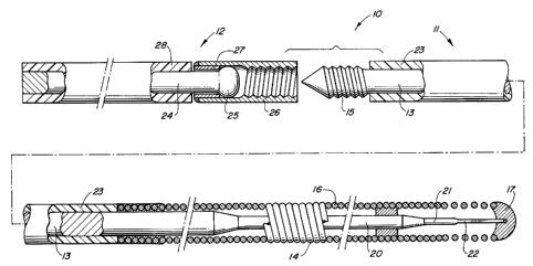
The Figure is a fragmentary, elevational view, partially
in section, of an extendable guidewire system embodying
features of the invention, with parts separated.
DETAILED DESCRIPTION OF THE INVENTION
As illustrated in the Figure, the guidewire system 10
embodying features of the invention has a main section 11
r 15 which is adapted to be inserted into a,patient's vascular
system and an extension section 12 which can be connected and
disconnected to the main section 11 to facilitate the exchange
of catheters without the need.for removing the main section
10 from the patient's vascular system. Main guidewire 11
~ generally comprises an elongated shaft 13 with a flexible
distal end 14 and a threaded male portion 15 at its proximal
end. The flexible tip 14, shown generally, has a helical coil
16 and a rounded distal tip 17. The elongated shaft 13 tapers
to: smaller diameter sections 20 and 21 and a last section 22
which i~ preferably flat. The length of the shaft 13 is
covered with polyethylene coating 23, as shown, up to the coil
16.
Extension section 12 has an elongated shaft 24 with an
enlargement 25 at its distal end. A freely rotatable
CA 02009839 1999-09-09
4
internally threaded female connection member 26 is secured to
the distal end of extension 12 by means of an internal collar
27 bonded thereto. The collar 27 has an internal diameter
less than the maximum radial dimension of the enlargement 25
but larger than the end of section 12 proximal to the
enlargement to facilitate the rotation of female member 26
independent of shaft 24.~ The enlargement 25 can be suitably
made such as by forming a weld ball on the distal end of shaft
24. The portion of the shaft 24 proximal to the female member
26 is covered with a plastic coating 28.
The main guidewire section 12 is intended for use in
positioning a dilatation catheter (not shown) in the arterial
system of a patient, and it has a length corresponding to the
length of a conventional guidewire for this purpose. Details
of typical dilatation catheters and guidewires can be found
in the patents cited previously.
Extension section 12 is sufficiently long so that when
the guidewire sections il and 12 are connected together, the
guidewire system 10 has an overall length suitable for
exchanging catheters without removing the main section 11 from
the patient's vascular system. With a dilatation catheter
having a length on the order of 90-130 cm, for example,
. section 11 might have a length of 110-150 cm, and section 12
might have a length of 100-130 cm.
Shafts 13 and 24 and female member 26 can be fabricated
from suitable material, such as stainless steel, nitinol (55%
Ni-Bal. Ti) or other suitable material, and each should have
a diameter to allow a dilatation catheter to pass freely over
them. Preferably, the two shafts 13 and 24 are provided with
a smooth transition between them. Either or both ~of the
shafts can be provided with a coating of polyethylene or
polytetrafluoroethylene, which is sold under the trademark
Teflon by the DuPont Corporation, or another suitable
5
material.
Typical dimensions of the main guidewire section include
a diameter of the shaft 13 of about 0.020 inch (0.5 mm), the
small diameter section 20 about 0.008 inch (.2 mm) to about
0.015 inch (.38 mm) in diameter and about 17 cm long, the
small diameter section 21 about 0 . 004 inch ( .1 mm) in diameter
and about 2 cm long and the flattened section 22 about 0.001
inch (.025 mm) to 0.003 inch (.076 mm) thick and about 3 cm
long. The coil 16 may be made of Teflon coated stainless
steel wire about 0.007 inch (.18 mm) in diameter and,
preferably, the distal section thereof is prestretched, as
shown. All or a portion of the coil 16 may be formed of more
radiopaque material, such as platinum, titanium, palladium and
alloys thereof. The proximal end of the coil 16 is preferably
bonded to the shaft 13 by a suitable adhesive such as a
cyanoacrylate. The polyethylene coating 23 on the shaft 13
is about 0.007 inch (.18 mm) thick to provide a smooth
transition to the coil 16. The threaded male member 15 is
about 0.5 to about 2 cm long and about 0.022 inch (.56 mm) in
maximum diameter. The distal tip is pointed to aid in entry
and has a diameter which facilitates the threaded connection
with the female member 26.
Typical dimensions of the extension section include a
diameter of about 0.015 inch (.38 mm) to 0.02 inch (.5 mm)
with a polyethylene coating thereon of about 0.007 inch (.18
mm) thick. The threaded female member is about 3 cm long and
about 0.035 inch (.89 mm) in outer diameter.
In use, the main guidewire section 11 is percutaneously
introduced into the vascular system of a patient with a
dilatation catheter through an introducer (not shown). The
distal tip of the guidewire is advanced beyond the distal tip
of the dilatation catheter while the latter. is held in place.
The main guidewire section 11 is advanced into the selected
6
artery. The guidewire tip is preferably advanced through the
lesion and bayond it, in order to permit the balloon portion
of the dilatation catheter to be positioned within the lesion
over a more supportive section of the guidewire. Once in
position, the main guidewire section 11 is held in place and
the dilatation catheter is advanced along it until the
inflatable balloon thereof is within the lesion. Threaded
male end portion 15 remains outside the patient's body and
outside any adapter which may be connected to the proximal
end of the dilatation catheter.
To exchange catheters, the main guidewire section 11 is
extended by manually threading the rotatable female tubular
member 13 on the threaded male member 15 on the distal end of
extension section 12. When the two guidewire sections are
threadably connected together, the dilatation catheter can
then be withdrawn from the pa'tient's body over the extended
guidewire system.
A new dilatation catheter may then be introduced over the
extension section 12 and advanced along the main guidewire
section 11 within the patient's body until the balloon crosses
the lesion. Once the proximal end of the new balloon catheter
has advanced beyond the threaded connection between female
member 26 and male member 15, section 12 can be removed by
rotating the female member 26 and then pulling the two
sections apart without disturbing the position of the main
section 11 in the patient's body.
The invention has a number of important features and
advantages., The two sections of the guidewire can be
connected together whenever a longer wire is needed, and they
can be separated whenever the additional length is not
required. The two sections of the guidewire may be connected
and disconnected by the physician by simply rotating the
threaded female member. This can be done as needed, and no
special tools are required wither to make the connection or
to separate it. Thus, the catheter exchange is greatly
simplified. The threaded connection provides the strength
frequently needed in peripheral procedures.
It is apparent from the foregoing that a new and improved
extended guidewire system has been provided. While the
present invention has been described herein with the tubular
connecting element fixed to the distal end of the main
guidewire section and the male member adapted to be inserted
into the open end of the tubular member on the distal end of
the extension section, it is obvious that the female connector
member and male connector member may be interchanged.
Moreover, it will be apparent to those familiar with the art
that other modifications and improvements can be made without
departing from the scope of the invention as defined by the
following claims.