Note: Descriptions are shown in the official language in which they were submitted.
Background of the Invention
This invention relates to -fishing devices and more par-
ticularly to improvements on the harness ~or a bait ~ish dis-
closed in my U. S. Patent 4,796,376.
Harnesses for b~it fish have long been used in a variety
of forms and shapes as exempli~ied in U. S. Patents, ~,189,860,
3,293,790, 2,582,646 and 3,457,666 and one of the important
objects of this invention is to provide impro~ements in con-
..
struction, design and versatility of use of such a harness as
compared with those presently in use.
Other objects herein are to providè a harness as character-
ized that has a minimum of parts Eor economy in manufacturc, is
simple and ease to use and is extremely ef~icient for its in-
tended purpose.
lS A further object is to provide a devicc of the above class
that is adapted ~or use with bait fish of varying sizes.
More particularly, it is an object o this invention to
provide a harness ~or a bait ~ish khat includes a clamp of
highly resilicnt spring matcrial bent to deine a closed end with
integral opposod sidos convergillg to ~rce onds biasod ~o an
abukting closed position ~or gripping the bait and provided with
prong fitted arms movable .iTl one diroction for openlng said ree
ends and movablc in the opposite direc~ion so the prongs will
penetrate tlle bait ~or additional gripping capability. In one
embodimeTIt, the clamp opcrably engages a skewer of any selected
lengtll th.lt is impaled lengtllwise o~ the bait; in a sccond em-
bodiment also used with a skewer, one arm is replaced by an
-1-
artificial lure for diversi~y in fishing techniques, and in
third embodiment ~or W]lic]l no skewer is uscd or nceded, the
cl?mp also has one arm replaced by an artificial lure fitted
Witll a plurality of depending barbs and includes an elongated
prong fi~ted shank ~or gripping and penetrating the bait ~ish.
A further object is to provide a harness as characterized
that, when used with a skewer, includes means to prcvent the
skewer from bein~ disengaged from the clamp.
A further object is to provide a skewer for this harness
that can be used with single,double or treble hooks.
Yet another object is to provide a harness as character-
ized that is adapked to carry other fishing attractants such
as a rubber skirt and the like and also a weight, i~ desired.
Summary
lS In accordance with this invention, a bait harness adapted
to hold a bait in the form of a ~ish or ~illet is providod for
casting, trolling or jigging. Tlle harness includos a clamp of
hi~hly resilient sprin~ matorial bent to define a closed end
with i~tegral opposed sides converging to ~ree ends biasod to
all abuttin~ closed position ~or grippin~ the bai~. In ono em-
bodimcnt, the clamp is providod with a pair of olon~a~od arms,
each ~itt~d with a pron~, pivotally mounted rcspectivo].y at one
end to respective ~roe onds oE the clam~ ~o opon thc same whon
pressod into en~agclllent Witll opposod sidcs therco~. This em-
bodiment is used with an olongatod skewor impaled lengthwiset}lrough the bait ~ish or ~illet so as to extend ~rom the ex-
tremities thereo~ and the bait is secured by mounting the clamp
to the leading end o~ the skewer so that the ~ree ends of the
2~1C~01~fi
clamp when closed tightly grip the bait and when the arms are
closed, the pron~s penetrate the bait for additional ~ripping.
The trailing end of the skewer carries a fish hook and the
leading end will receive a fishing line. The clamp is designed
so that, when closed~ the skewer c~nnot be detached Additional
hooks can be attached to the clamp. In a second em~odiment,
also used with a skewer, the arm adjacent one side of the clamp
is replaced by a buo~ant artificial fishi.ng plug attaclled to
said side to provide for variation in fishing techniques. A
third embodiment modiies the second embodiment by providing
the ishing plug with a trailing tail to receive a ~ish hook
and a plurality of depending spaced pointed barbs. ~ hook may
be attached to the clamp, i~ desired. Securely attaclled to the
arm side o~ the clamp is an elongated shank fitted with an
angularly disposed prong whereby the clamp can be secured to the
bait and the prongs on the arm and the shank and the barbs on
the plug penetrate the bait to securely hold it in place. A
skewer i.s not used nor needed with tile third embodirnont.
. Tlle ~oregoing objects and sucll ~urther objects ~s may
appear herein, or bo here:inater pointed out, to~etllor with the
advanta~es o~ this invon~:Lon will be more ~ully discussed and
developed~ in th~ moro do~a:Llod description ol: the accompanying
drawings.
13rio~ Descript~on o~ the Draw:in~s
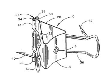
Fig. l is a perspective view o one embodiment o~ the bait
~iS]I on~a~in~ cl~mp accordin~ to this invention,
Fig. 2 is a plan view from the top of Fig. 1,
-3-
~ ~Q ~
Fig. 3 is a side elevational view of thc dev.ice shown
in Fig. 1,
~ig. 4 is a top ~icw o~ thc clamp in Fig. 1 coacting with
a skewer for securing a bait fish,
I:ig. 5 is a side elevational view of the showing in Fig. 4,
Fi~. 6 is a side elevational view similar to Fig. S but
showing the use of a single hook used whcn the trailing end of
the skewer is drawn into the bait fish,
Fig. 7 is a view similar to Fig. 4 but showing additional
fish hooks on the clamp,
Fig. 8 is a side elevational view of a second embodiment
of this invention showing a fishing plug attached to the clamp
and illustrating a ~ish hook depending from the cl~mp and thc
arms of the clamp in closed position,
lZig. 9 is an elevational view o~ a modified ~orm o~ a
skewor usable with this invention,
Fig. 10 is a side elevatiollal view o~ a third embodiment
o~ this invcntion showing the plug and clslmp o~ . 8 modiied
~or uso without 3 skewor, and
~ig. 11 is a viow s:ilnilar to l~:ig. 10 sllowillg ~his harness
securillg a bait ish.
Descrip~ion o~ thc l'rcferrod ~mbodiments
Re~errillg to thc drawings, the embodimollt o~ the clalup in
t]liS :Lnvontion designated by the nullleral 10 as best seen in I:igs.
1,2 is adapted ~or use with a skewcr 12 for holding a bait fish
1~ and is morc particularly described as ollows.
Clamp 10 is a modification of what is generally rcferred
to as a binder clip and includes a body of highly resilient ~lat
spring material bent to define a closed end 16 which is
cehtrally apertured as at 18., and integral sides 20, 22 con-
verging so ~heir free ends are normally biased to abut~ing
closed position as indicated at 24. The outer end portions
on the ou~er surface ,of side 22 are bent up and aroun~ to
form the respective collars 26, 28 and side 20 is similarly
~ormed or which one such collar 30 is shown in ~ig. 1 opposite
collar 26 and it will be understood a similar collar is pro-
..
vided opposite collar 28. ~n elongated generally U-shaped
arm 32 has each ~ree end bcn~ perpendicularly outward to ~orm
the stub shafts 34 that are pivotally journalled in the rcspec-
tive collars 26, 28 so as to be movable into and out o~ engage-
ment with side 22 (Fig.3) or in the opposite direction so as to
project Erom clamp 10 15 will later appear and a like arm 36
.wi~h stub shafts 38 is similarly arranged relative to side 20.
Arms 32, 36 hlve the respoctive porpendicularly projecting
barbed ~rongs ~0, 42 that extend outwardly relative to clamp 10
when positioned as seen in ~ig. 3 and will thus be in an
opposed relationship when they are fully moved in the opposite
direction as will become apparent.
The skewer 12 used with this harness is o~ an elongated
needlo-lik~c con:~iguratiun, pre~crably pointed antl apcrtured at
bot}l i~s leading end ~4 and trailing cnd ~6 as seon in Fig. 4,
and is provided with a concentrically enlar~ed stop or collar
48 spaced a short distance inwardly ~rom the leading cnd 44.
Such skewer 12 can be o~ any desired length depending upon the
requirement according to the length of the bait fish 14 used
--5--
and thus a ~isherman can carry a wide assortment of sizes for use
as needed with a single clamp 10. Skewer 12 as shown is of a flat
bendable matcrial ~or selectivc bending to increase tho wobble of
plug 72 but may bc a bendable rod 50 (~ig.9) with a collar 48 as
d~scribcd ~nd with an eye 52 on its leading end 54 and a loop 56
on the trailing end 58 for hook 60. Skewer 12 is adapted ko re-
movably receive a clip 62 and hook 64 on the trailing end 4G and
hooks 60, 64 may be sin~le, double or triple as may bc desired.
In using the above dcscribed harness, a skewcr 12 of any
selectcd lcngth ncedod ~or the size of bait ~ish 14 chosen is
impaled lengtllwise and ccntrally o the bait fish.l4 from the
mouth thorcof through the tail so that the collar or stop 48
is positioned in close ~roximity to thc frollt of the mouth of
bait fish 14. Clamp 10 is thon opened by pressin~ the closed
ends o~ the arms 32, 36 towards ca'ch othor against the res'pective
sides 22, 20 in which position the leading ond 44 o~ skcwer 12
is jollrnallod througll aperturo 18 in clamp 10 until stop 48
abuts kho inncr sidc o~ closed cnd 16 o clamp 10 and the clamp
can bo ti~htly closcd in gripping ongagement with rcspcc~ive
op~ositc sidos o tho ~isllls hcad or cnd o~ a ~illet. Arms 32,
26 are thon rotutod to projcct roarwardly rom clamp 10 where
pron~s ~0, 42 will bo in an opposin~ ro:Lationship and can be
i.mboddod in thc bai.t ish 14 ~rom rospcctive opposite sides
~llcroo~ (Fi~.~) wllcrc~y bait 1~ is sccuroly l)osi~io~cd ~or cast-
ing or trolling. Any suitablc hook 64 is then a;ttached 'to the
trailill~ end 46 as shown. The leuding'end 44 is adapted to ro-
ccive a suitable clip 66 and ;ishing line 68, and, i~ dcsired,
0~
a weight or the like 70 can be placed on the leading cnd 44 as
best seen in Fig. 4. Bo~ll the leading end 44 and the trailin~
end 46 of skewer 12 are pre~erably pointed as described and while
this is not necessarily required, it facilitates the impalement
of the skewer 12 and particularly Wit]l the leading end 44 pointed,
it is helpful to those fishcrmen who choose to keep skewers 12
of varying lengths with hooks attached to the trailin~ end 46 to
impale t]le bait 1~ ~rom tail to head.
In a second embodiment of clamp 10 as seen in F;ig. 8, arm
36 on side 20 of clamp is replaced by a buoyant artificial plug
lure 72 with a projecking apertured lip 74 of the type disclosed
in my U. S. Patent 4,796,376. With such an attached lure, the
leading end 44 of skewer 12 is cxtended through the apcrture
in lip 74 and such an arrangement provides ~or variation in
fishing techniques as is well known. ~lso, Eor additional hook
capability, clamp 10 may, itself, be provided with one or more
hooks 76 as seen in ~igs. 7,8.
As described above, skewe~ 12 normally projects ~rom both
the hea~ and t~il of the b~it :ish 14 with a danglin~ hook 64 on
the trail:in~ end ~6. Such a hook position i5 subjcc~ to entangle-
ment in weeds and snag pronc areas and I show in ~:i.g. 6 an ad-
aptation,o~ this llarr.~ss whcro skewer 12 is used so that the
trailing end ~6 can bc drawn into thc tail portion of the bait
Eish 14 to rcccivc ~ single ~ish hook thcn held in general linear
aligmnent with the direction of forward movement and thereby less
likely to be snagged.
Thus ~ar doscribed, it will be appreciated that this harness
--7--
has a minimum of parts with a maximum of gripping powcr on
the bait provided not only by the clamp itself but by the
additional gripping of the prongs 40, 42 on the clamp arms 3Z,
36. The bait 14 is thus held securely and cannot slide down
the skewer 12 and bunch up at the trailing end 46. The stop
48 which abuts the inner side of clamp end 16 is designed lar~e
enought so it cannot pass throu~h aperture 18 whereby ~he skewer
12 cannot be pulled through the clamp from the leading end 44
by a predator or the like. Likewise, a clip 6G~at the outer
side of clamp 10 will not pass through aperture 18 and thus
provides a second stop whereby the skewer 12 cannot be pulled
through clamp 10 from the trailing end 46 so that this harness
is extremoly e~ective and useful for its intended purpose.
With referonce now to Figs. 10, 11, I show a modification
of plug 72 of ~ig. 8 as a third embodimont that does not use or
require a skewer 12 and in describing this embodiment, liko
numerals will be given to like parts previously described.
The relationship of plug 72 and arm 32 with prong 40 on
clamp .lO is the same as previously described. I-lowever, in this
tllird embodilllellk, plug 72 i~ provided witll an elongated b~nd.lble
tail 78 to roceive a hoolc 64, an eye hook 80 on lip 7~ to receive
u clip G)6 und fislling line G8 ulld a plurality o~ depondillg spacod
barbs 82 as shown. ~n elongatod shank 8~ is socured at one end
por~ion ~o side 22 of clamp 10 in~e~media~e collars 26, 28 and
projec~s ~here~rom to a point near or beyond the rear o plug 72
to terminate in an upturned pro~erably bifurcated prong 86.
With the above modifications, clamp 10 in the third embodimen~
2 ~ 6
is c~sily opencd to the do~ted line position shown in Fi~. 10
by pressin~ arm 32 against side 22 towards plug 72 to simul-
taneously opcn shank 84 and in which position as scen in Fig.
11, b~it 14 is securc~ by the combined grippin~ capability of
the penctrating pron~s 40, 86 and barbs 82 on plug 72 at a
plur~lity of spaced points intermediatc the len~th of thc bait
14 as well as by thc clamp 10, itself~ The easy manipulation
of clamp 10 facilitates not only the original attachment of a
bait 14 but the quick and easy replacement thereo if it is
damagcd by a strike or snag and the bendability o~ tail 78
pcrmits it to be sclcctively bcnt for enhancing the wobble and
sidc to sidc action of plug 72 when it is pulled through the
watcr. Accordingly, in view of thc foregoing, it is thought
a full understanding of the construction and operation of this
invcntion will be had and the advantages of the samc will be
appreci.ated.