Language selection

Search

Patent 2010034 Summary

Third-party information liability

Some of the information on this Web page has been provided by external sources. The Government of Canada is not responsible for the accuracy, reliability or currency of the information supplied by external sources. Users wishing to rely upon this information should consult directly with the source of the information. Content provided by external sources is not subject to official languages, privacy and accessibility requirements.

Claims and Abstract availability

Any discrepancies in the text and image of the Claims and Abstract are due to differing posting times. Text of the Claims and Abstract are posted:

  • At the time the application is open to public inspection;
  • At the time of issue of the patent (grant).
(12) Patent: (11) CA 2010034
(54) English Title: APPARATUS AND METHOD FOR CUTTING MEAT
(54) French Title: APPAREIL ET METHODE DE COUPE DES VIANDES
Status: Expired
Bibliographic Data
Abstracts

English Abstract


Abstract

The present invention relates to an apparatus and method of
cutting meat. The apparatus and method is particularly
directed to separating a backbone portion from a rib portion
of a piece of meat. The apparatus is comprised of a vertical
orientation unit for vertically orienting the piece of meat.
The orientation unit includes a longitudinal receiving channel
having a generally horizontal top surface, the surface having
a slot. The width of the slot accommodates the rib portion
but not the backbone portion so that the backbone portion is
held above the orientation unit. A moving unit is provided
and is adapted to contact the backbone portion for moving the
piece of meat horizontally in the direction of the
longitudinal axis of the channel. A cutting unit is provided
which includes a saw blade, a portion of which is oriented
horizontally, wherein the cutting unit horizontally cuts the
rib portion from the backbone portion.


Claims

Note: Claims are shown in the official language in which they were submitted.

7
In the claims:
1. An apparatus for use in separating a backbone portion
from a rib portion of a piece of meat, the apparatus
comprising:
a vertical orientation means for vertically orienting the
piece of meat, the orientation means including a longitudinal
receiving channel having a generally horizontal top supporting
surface, said surface having a slot, the width of which
accommodates the rib portion but not the backbone portion so
that the backbone portion is held above the orientation means
by said top surface;
a moving means, located above said orientation means,
adapted to contact the backbone portion for moving the piece
of meat horizontally in the direction of the longitudinal axis
of the channel; and
a fixed cutting means which includes a saw blade, a
portion of which is oriented horizontally and fixed
horizontally with respect to said top supporting surface of
said orientation means, wherein the cutting means horizontally
cuts the rib portion from the backbone portion.

2. The apparatus of claim 1, further comprising a second
longitudinal channel longitudinally aligned with said
receiving channel, the second channel having a top surface
which is aligned with the top surface of said receiving
channel, said cutting means being located between said
receiving channel and said second channel.

3. The apparatus of claim 2, wherein the second channel is
open at the bottom and has slot longitudinally oriented in the
top surface.

4. The apparatus of claim 3, wherein circular beads are
affixed to edges of the slots in the receiving channel and the
second channel to facilitate the smooth movement of the piece
of meat.


5. The apparatus of claim 4, further comprising first and
second angled walls connected along the front edges of the
slot in the receiving channel, the first and second angled
walls each being angled upwardly and outwardly to facilitate
the vertical orientation of the piece of meat.

6. The apparatus of claim 5, further comprising plate means
angled from the horizontal and partially inserted in the
opening at the bottom of the second channel, wherein the plate
means receives a severed rib portion, and moves said severed
rib portion downwardly and to the side out of alignment with
the receiving channel and the second channel.

7. The apparatus of claim 6, further comprising a conveyor
means for receiving the severed rib portion from said plate
means for moving said severed rib portion to the front of said
apparatus.

8. The apparatus of claim 7, further comprising a second
conveyor means located at the rear of the apparatus for
receiving the severed backbone portion from said moving means.

9. The apparatus of claim 7, wherein said moving means is a
chain conveyor comprising a horizontally oriented chain means
located between a drive sprocket and an idler sprocket, said
chain means having connected thereto a plurality of tine means
which engage the backbone portion of the piece of meat.

10. The apparatus of claim 9, wherein the chain means extends
generally parallel and above the top surfaces of the receiving
channel and the second channel.

11. The apparatus of claim 10, wherein the cutting means
comprises a band saw means having first and second pulleys
vertically oriented in a plane perpendicular to the

9
longitudinal axis of the receiving channel, and a band saw
blade located around the first and second pulleys such that
the working portion of the band saw blade is substantially
horizontal and aligned with the top surface of said receiving
channel.

12. The apparatus of claim 11, wherein the moving means, the
cutting means and the conveyor means are driven by hydraulic
motors.

13. The apparatus of claim 11, further comprising a knife
means connected across said first and second angled walls,
wherein said knife means severs a tail portion from the
backbone portion of said piece of meat.

14. A method of severing a backbone portion from a rib portion
of a piece of meat, the method comprising the steps of:
providing a horizontally oriented support surface;
vertically orienting the piece of meat on said support
surface so that said backbone portion is above said rib
portion and above said support surface;
providing a fixed horizontal sawing station which is
fixed horizontally with respect to said support surface; and
providing a moving means for mechanically moving said
piece of meat through said sawing station by contacting said
backbone portion to thereby sever said backbone portion from
said rib portion.

Description

Note: Descriptions are shown in the official language in which they were submitted.


20~
APPARATUS AND METHOD FOR CUTTING MEAT

The present invention relates to an apparatus and method for
cutting meat and more particularly for separating a backbone
portion from a rib portion in pork.

The prior art method of separating the backbone from the ribs
of a pig employed a vertically oriented band saw. The ribs
and backbone were merely sawn in two parts in a fashion
similar to that of cutting a piece of wood. The rib and
backbone sections are naturally damp and slippery as is all
meat and the operator has to be very careful not to injure his
hands or fingers when pushing the meat through the saw. This
~ prior art method causes many injuries to the operator since it
- is standard practice to try to cut the ribs for maximum length
and this entails pushing a relatively small backbone section
into the saw. Since the backbone section is small in cross
section and since the operator must press on the end of the
backbone cross section during its entire passage through the
saw, frequent injuries occurs, especially when experienced
operators became complacent.
'
The present invention overcomes this difficulty by providing a
band saw component which cuts the meat in a horizontal plane
and which mechanically feeds the meat into the sawing section
so that the operator does not place his hands or fingers near
the saw blade.

orienting the saw blade horizontally necessitates the re-
orientation of the backbone-rib combination. This is
accomplished by providing a slotted element which accommodates
the rib section while leaving the wider backbone section
exposed to the saw blade.

With the rib section vertically oriented, the backbone is
located outside the slotted section of the apparatus and


, .

03~

engages the tines of a chain type conveyor which pulls the
meat into the horizontally oriented band saw.

In preferre~ embodiments, conveyor mechanisms are provided
which remove the backbone from the vicinity of the machine
once it is cut from the ribs and which move the rib section to
a convenient location for packaging by the operator.

The apparatus of the present inventlon is not only much safer
to use than prior art methods, it has improved the efficiency
of the operator.

In accordance with the present invention there is provided an
apparatus for use in separating a backbone portion from a rib
portion of a piece of meat, the apparatus comprising: a
vertical orientation means for vertically orienting the piece
of meat, the orientation means including a longitudinal
receiving channel having a generally horizontal top surface,
said surface having a slot, the width of which accommodates
the rib portion but not the backbone portion so that the
backbone portion is held above the orientation means; a moving
means adapted to contact the backbone portion for moving the
piece of meat horizontally in the direction of the
longitudinal axis of the channel; and a cutting means which
- includes a saw blade, a portion of which is oriented
horizontally, wherein the cutting means horizontally cuts the
rib portion from the backbone portion.

In accordance with another aspect of the present invention
there is provided a method of severing a backbone portion from
a rib portion of a piece of meat, the method comprising the
steps of: vertically orienting the piece of meat so that said
backbone portion is above said rib portion; providing a
horizontal sawing station; and mechanically moving said piece
of meat through said sawing station to thereby sever said
backbone portion from said rib portion.

34
.


The present invention will be described in detail hereinbelow
with the aid of the accompanying drawings, in which:

Figure l is a perspective schematic diagram of a pork
backbone-rib section to be sawn;

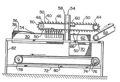
- 5 Figure 2 is a schematic side elevational view of one
embodiment according to the present invention;

Figure 3 is a schematic front elevational view, partially
broken away, of the embodiment of Figure 2; and

Figure 4 is a top plan view of the embodiment of Figure 2.

Figure 1 shows a typical backbone-rib section 10 of a pig.
Prior to obtaining this portion the pig is slaughtered and cut
down the middle to form two sections. As a result each pig
will yield two portions shown in Figure 1.

The section 10 is comprised of three parts. A rib portion 12
consisting of a plurality of rib bones 14 interleaved with
strips of meat 16. It is this rib portion 12 which of value.
Rib portion 12 is connected to a backbone portion 18, which is
actually one half a backbone, the other half already having
been cut away and associated with another rib portion. The
backbone is comprised of bone and cartilage and is of no
value. In order that the rib portion be of any value, it must
be separated from the backbone.

A small tail section 20 is connected to the backbone portion
18 and one option of the apparatus according to the present
invention separates this tail section 20 from the backbone
portion 18. The tail section 20 is of some value.

The present invention separates the rib portion 12 from the
backbone portion 18 along a cut line 22. The cut line 22
should be located such as to maximize the usable meat making

Z~lQ(~

up the rib portion. The apparatus can also optionally
separate the backbone portion 18 from the tail section 20
along cut line 24.

The apparatus according to the present invention will now be
explained in detail with the aid of Figures 2, 3 and 4.

A horizontally oriented longitudinal rectangular receiving
channel 30 has a slot 32 located in its upper surface. Each
- edge of the slot has a circular bead 34 welded thereto to
allow a smooth movement of the meat through the apparatus.
Angled side walls 36 are welded to the front region of the
slot to aid in guiding and vertically orienting the meat into
the slot.

An optional cutting blade 38 is fixed across the leading end
of the side walls 36 and is used to cut the tail section 20
from the backbone 18 shown in Figure 1.

The backbone-rib section is shown in dashed lines in Figures 2
and 3. The slot 32 must be wide enough to accommodate the rib
portion 12 but narrow enough to stop the backbone portion 18
from entering the channel 30.

A chain type conveyor 40 is located above the channel 30 and
has its working portion oriented generally parallel to the top
surface of the channel 30. The conveyor 40 is powered by an
hydraulic motor 42 which drives a sprocket assembly 44. A
chain unit 46 is located around sprocket assembly 44 and
extends to another sprocket assembly 48. A plurality of
angled tines 50 are located at various points along chain unit
46. The tines 50 engage the top surface of the backbone
portion 18 and move the meat along the top surface of the
channel 30.

A band saw unit 52 is located at the rear end of channel 30
such that the blade 54 is aligned with the top surface of

~0~()034


channel 30. ~he band saw unit 52 comprises the ~lade 54 which
engages the outer s~rface of two pulleys 56 and 58. Drive
pulley 56 is driven by an hydraulic motor 60. The working
portion of the band saw assembly is oriented generally
horizontally.

A second horizontally oriented longitudinal rectangular
channel 62 is located directly down stream of the band saw
assembly 52 and is longitudinally aligned with the receiving
channel 30. Channel 62 is also fitted with a slot 64 on its
top surface. In order to insure the smooth movement of the
severed backbone along the channel 62, a circular bead 66 is
welded along each side of slot 64.

The backbone portion 18 which has been sawn from the rib
portion 12 is driven along the top surface of channel 62 by
chain conveyor 40. The backbone portion 18 proceeds in this
manner to the rear of the machine where it can fall into a
container (not shown). As is shown in Figure 2 the backbone
` portion 18 can optionally be fed to a conveyor 68 which
removes it from the proximity of the apparatus. Figure 2
shows the severed backbone in dashed lines being removed by
conveyor 68.

The channel 62 is open at its bottom. An angled plate 70 is
located in this open area. The angled plate 70 receives the
severed rib portion and moves it downwardly and to the side
away from the longitudinal alignment of the channels 30 and
62. Angled plate 70 delivers the severed rib portion to a .~
conveyor 72.

Conveyor 72 is comprised of a drive roller 74, driven by
hydraulic motor 76, an idler roller 78 and a belt 80. The
severed rib portion falls on the belt 80 and is moved to the
front of the machine where it comes into contact with stop
plate 82 and is then removed for packaging by the operator.

6 2(~003~
The apparatus of the present invention is preferably
fabricated from stainless steel in order to facilitate
cleaning.

This embodiment of the invention :is powered by hydraulic
motors. This is preferred because it eliminates electricity
from an area which must be washed down with water frequently.
Sealed electric motors and controls could be used and the
invention is not limited to the use of hydraulic power.

The depth of the channels 30 and 62 and the width of the slots
32 and 64 can be adjusted to accommodate types of meat other
than pork. This invention is not limited to severing the
backbone portion and the rib portion in pork.

Representative Drawing
A single figure which represents the drawing illustrating the invention.
Administrative Status

For a clearer understanding of the status of the application/patent presented on this page, the site Disclaimer , as well as the definitions for Patent , Administrative Status , Maintenance Fee  and Payment History  should be consulted.

Administrative Status

Title Date
Forecasted Issue Date 1993-01-05
(22) Filed 1990-02-14
Examination Requested 1990-02-14
(41) Open to Public Inspection 1991-08-14
(45) Issued 1993-01-05
Expired 2010-02-14

Abandonment History

There is no abandonment history.

Payment History

Fee Type Anniversary Year Due Date Amount Paid Paid Date
Application Fee $0.00 1990-02-14
Registration of a document - section 124 $0.00 1990-08-22
Maintenance Fee - Application - New Act 2 1992-02-14 $100.00 1992-01-27
Registration of a document - section 124 $0.00 1992-11-10
Maintenance Fee - Patent - New Act 3 1993-02-15 $100.00 1993-02-11
Maintenance Fee - Patent - New Act 4 1994-02-14 $100.00 1994-01-19
Maintenance Fee - Patent - New Act 5 1995-02-14 $150.00 1995-02-01
Maintenance Fee - Patent - New Act 6 1996-02-14 $150.00 1996-02-01
Maintenance Fee - Patent - New Act 7 1997-02-14 $150.00 1997-02-06
Maintenance Fee - Patent - New Act 8 1998-02-16 $150.00 1998-01-20
Maintenance Fee - Patent - New Act 9 1999-02-15 $150.00 1999-01-19
Maintenance Fee - Patent - New Act 10 2000-02-14 $200.00 2000-01-12
Maintenance Fee - Patent - New Act 11 2001-02-14 $200.00 2000-12-15
Registration of a document - section 124 $0.00 2001-01-25
Maintenance Fee - Patent - New Act 12 2002-02-14 $200.00 2002-01-14
Maintenance Fee - Patent - New Act 13 2003-02-14 $200.00 2003-01-16
Maintenance Fee - Patent - New Act 14 2004-02-16 $200.00 2003-12-15
Maintenance Fee - Patent - New Act 15 2005-02-14 $450.00 2005-01-21
Maintenance Fee - Patent - New Act 16 2006-02-14 $450.00 2006-01-17
Maintenance Fee - Patent - New Act 17 2007-02-14 $450.00 2007-01-17
Maintenance Fee - Patent - New Act 18 2008-02-14 $450.00 2008-01-17
Maintenance Fee - Patent - New Act 19 2009-02-16 $450.00 2009-02-05
Owners on Record

Note: Records showing the ownership history in alphabetical order.

Current Owners on Record
OLYMEL S.E.C./OLYMEL L.P.
Past Owners on Record
COOPERATIVE FEDEREE DE QUEBEC
OLYMEL, SOCIETE EN COMMANDITE
PERREAULT, MARTIN
Past Owners that do not appear in the "Owners on Record" listing will appear in other documentation within the application.
Documents

To view selected files, please enter reCAPTCHA code :


To view images, click a link in the Document Description column. To download the documents, select one or more checkboxes in the first column and then click the "Download Selected in PDF format (Zip Archive)" or the "Download Selected as Single PDF" button.

List of published and non-published patent-specific documents on the CPD .

If you have any difficulty accessing content, you can call the Client Service Centre at 1-866-997-1936 or send them an e-mail at CIPO Client Service Centre.


Document
Description 
Date
(yyyy-mm-dd) 
Number of pages   Size of Image (KB) 
Cover Page 1994-07-09 1 12
Abstract 1994-07-09 1 24
Claims 1994-07-09 3 112
Drawings 1994-07-09 2 59
Description 1994-07-09 6 218
Representative Drawing 1998-06-19 1 19
Fees 1999-01-19 1 46
Fees 2000-01-12 1 37
Correspondence 2003-01-16 2 53
Correspondence 2003-01-28 1 15
Fees 2003-12-15 1 37
Correspondence 2003-01-28 1 13
Fees 2003-01-16 1 41
Fees 1998-01-20 1 44
Fees 2002-01-16 1 41
Correspondence 2001-01-25 1 21
PCT Correspondence 2000-12-18 3 168
Prosecution Correspondence 1991-10-09 2 51
Office Letter 1990-08-27 1 20
Correspondence 1997-10-16 2 81
Fees 2000-12-15 2 76
Office Letter 1990-09-28 1 36
Office Letter 1997-11-05 1 15
Fees 2005-01-21 1 39
Office Letter 1997-11-05 1 12
Office Letter 1991-06-10 1 48
Prosecution Correspondence 1990-06-27 2 72
Fees 2006-01-17 1 43
Fees 2007-01-17 1 42
Fees 2008-01-17 2 61
Fees 2009-02-05 1 61
Fees 1997-02-06 1 47
Fees 1996-02-01 1 53
Fees 1995-02-01 1 69
Fees 1994-01-19 1 78
Fees 1993-02-11 1 50
Fees 1992-01-27 1 48