Note: Descriptions are shown in the official language in which they were submitted.
Z~0097
BACRGROUND OF THE INVENTION
This invention relates to a method and apparatus for
detecting and analyzing gear defects.
Several attempts are disclosed in the prior art literature
to analyze vibrational systems. Many of those attempts are
highly complex and limited in their capability.
U. S. Patent No. 4,520,674 entitled VIBRATION MONITORING
DEVICE is typical of recent prior art systems. A signal
generated by a vibration monitor is initially processéd by a
signal conditions module which includes anti-aliasing filters to
enhance the accuracy of the data collected. Further pre-
processing is performed by a multi-function module which also
increases the speed and reliability of the system. The data is
subsequently analyzed by a microprocessor and displayed if
desired on a monitor.
U. S. Reissue Patent No. RE 31,750 entitled DATA ACQUISITION
S~STEM is similar to the foregoing concept. Signal information
is brought into a multi-channel multiplexer. Signal pick up is
performed by self-amplified accelerometers. The system
subsequently performs trend analysis on the historical data which
consists of representative amplitudes of stored electrical
signals.
~`
`i~ 20~0097
U. S. Patent No. 4,429,568 entitled ACOUSTICAL DEFECT
DETECTION SYSTEM describes an invention in which the incoming
slgnal is also preconditioned. The preconditloning 15 performed
through the use of amplifiers, a high pass filter, a low pass
filter, a full wave rectifier and an analog/digital converter.
U. S. Patent No. 4,574,633 describes APPARATUS FOR DETECTII~G
TOOL DAMAGE IN AUTOMATICALLY CONTROLLED MACHINE TOOLS wherein
historical data is compared to present data.
The following prior art patent references describe possibly
relevant systems for detecting the deterioration of gears. U. S.
Patents 3,758,758; 3,842,663; 4,335,612; 4,550,603 and 4,550,604.
Certain of the foregoing patents relate to specific types of
gears. For example, U. S. Patent No. 3,758,758 relates
specifically to the meshing of helicopter gears and U. S. Patent
No. 4,335,642 relates to a method of detecting irregularities on
beveled gears. U. S. Patent Nos. 4,550,603 and 4,550,604 both
relate to gear inspection techniques.
Lastly, the prior art patent literature describes other
systems of lesser relevance. For example, U. S. Patent No.
4,352,293 includes a detailed description of Fourier analysis.
U. S. Patent No. 3,913,084 includes a discussion of the use of
accelerometers in the context of noise detectors and analyzers.
U. S. Patent No. 3,694,637 describes a relatively simple system
for analyzing wear on a tool in which a minicomputer is used for
the purpose of analyzing the ultimate results.
2~0097
A common method for performing vibration (or acoustic,
torque, or force) based analysis of operating gear systems
-involves use of spectrum or cepstrum analysis lnstrumentation.
This instrumentation allows amplitude estimation of vibrations
related directly to gear tooth meshing frequencies. These
amplitudes are then compared over time or between like machines,
and conclusions on gear status are reached. Such methods give
overall measures of gear performance and are not very sensitive
to defects localized on the gear, and are subject to background
interference. In addition, observations over time, or
comparisons between similar machines is required to interpret
these measures. The present invention describes a method for
obtaining more detailed gear condition information on a tooth-
by-tooth basis, and allows comparison among the teeth for
interpretation. Disclosed are methods to extract the tooth-by-
tooth information in the presence of numerous forms of
interference, and to allow construction of a gear diagnostic
image for further examination.
Another approach, explored specifically in the helicopters
preventive maintenance industry, involves time domain averaging
of vibration signals and computing statistical measures such as
the fourth and sixth moment, from these time domain averages.
Changes in these measure over time is the basis of the approach.
This technique does not produce a tooth-by-tooth level of
analysis and is subject to interference, thereby limiting its
sensitivity and reliability in such applications.
20 ~ 0097
-
Insofar as understood, none of the prior taken individually
or in combination teach or suggest the present invention which
includes, among other things, the capability of analyzing
tooth-to-tooth interactions over a long period of time, and
then stacking the interactions in such a way as to make a gear
defect detectable.
This invention provides a method for analyzing a gear
system having at least two inter-dash meshing gears, comprising
the steps of sensing data signals produced by tooth-to-tooth
contact in the gear system as the gears revolve; acquiring
additional data from the system, including the number of teeth
on each gear, the gear system configuration, and the given
machine operating state; identifying from the combined data
which includes the additional data and the data signals, the
relative angular orientation of the gears in the system and the
data generated to the orientation; and analyzing the combined
data to compute gear system vibrational characteristics. At
least some of the data is sensed by shaft encoders. The data
signals include signals from at least two top-dead-center
pickup means for determining the unique angular orientation of
each gear of the gear system.
In one aspect, this invention provides a method for detecting
gear defects in a system having at least four gears, comprising
the steps of collecting signal data relating to the interaction
of a first pair of gears which includes a first gear and a
second gear, collecting signal data from a second pair of gears
which
.~
, t ~
20 1 0097
includes a third gear which interacts with a fourth qear,
combining the signals collected from the first, second, third
and fourth gears together to form a giant hunting tooth
pattern, and detecting the envelope of the giant hunting tooth
pattern. The third gear and the first gear are located on a
common shaft. The period of peaks of the envelope which
corresponds to the hunting tooth of either pair indicates on
which pair of gears of a defect is likely to be found.
In another aspect this invention provides a method of
analyzing a vibrational signal generated by the inter-meshing
of at least two gears, stacking at least two of the signals so
that identical tooth-to-tooth matings are superimposed on each
other and determining which tooth-to-tooth interactions have
anomalous patterns. The analysis comprises the steps of
sensing the vibrational signal at least long enough for each
tooth of the gears to mate once before repeating. The
tooth-to-tooth interactions have anomalous patterns determined
above are likely to include a gear having a defect therein.
In another aspect, this invention includes a system for
analyzing a vibrational signal generated by at least two
inter-meshing gears, an interface connected to the pick-up, an
analogue signal process or means connected to the interface for
conditioning and converting the signal to a digital signal, a
computer means connected to the analog signal processor means
for recording the digital signal over at least one hunting
tooth period of the gears and stacking at
- 4A -
20 1 0097
-
least two of the signals so that tooth-by-tooth interactions
are superimposed on each tooth, and, an output means for
reporting the results of the operations performed by the
computer means. The system comprising a vibrational signal
pick-up mountable on the object.
In another aspect, this invention provides a method for
detecting the location of a defect in a gear system of at least
two gears, the method comprising the steps of generating a
series of hunting tooth patterns of the tooth by tooth
interactions of at least two gears, and, comparing the hunting
tooth patterns generated over time against each other to locate
local gear defects. The hunting tooth patterns are as long as
it takes for each tooth by tooth interactions to repeat itself.
In yet another aspect, this invention also provides a ~`~
method for analyzing a vibrational signal generated by at least
two-intermeshing gears, comprising the steps of detecting the
vibrational signal, high frequency band pass filtering the
vibrational signal, detecting the envelope of the high
frequency band pass filtered signal to produce a signal
representative of the low frequency components of the
vibrational signal, and stacking at least two of the envelopes
so that vibrations of the same tooth are superimposed on each
other. The stacking of the æaid envelopes produces an
indication of gear tooth anomalies.
- 4B -
;O' ,,, ~
~ 20 1 0097
Briefly described, the invention comprises a method and
apparatus for performing advanced vibration analysis. Signals
from an accelerometer and a shaft encoder are fed through an
interface circuit to an analog signal preprocessor prior to
being fed into a microcomputer. The analog signal preprocessor
typically passes the signal through full wave rectifiers and
low pass filters to demodulate the signal in order to e~tract
the amplitude envelope. The envelope is then supplied as an
input to an analog/digital converter so that the signal can be
processed by the microcomputer. The signal may also be
conditioned in other manners depending upon the nature of the
phenomenon being investigated. The digitized signal is then
classified by the system based upon specific properties of the
signal and the signal is processed to compute the optimal time
domain average. Thereafter, the signal is further processed by
the computer to identify and eliminate spectral components and
to eliminate interference after which computations are made to
measure gear wear and detect gear defects. Time history
analysis is performed
- 4C -
.,~ 2135b/1-4
2(~10097
within a given system operating state and alarm logic is used to
alert the system user if there are significant changes in status.
Ultimately the results are presented in the form of a status
report, a monitor display and/or an automated alarm or shut down
reaction.
One important advantage of the system is its ability to
employ hunting tooth vibration pattern analysis to analyze the
intermeshing reaction of two or more gears. Each tooth-to-tooth
interaction is recorded until the pattern begins to repeat.
Subsequent recordings are averaged with respect to previous
records to produce a unique pattern to identify which tooth-to-
tooth interaction is likely to involve defective teeth.
Subsequent analysis makes it possible to detect which of the
teeth in the tooth-to-tooth interaction is likely to be the
defective tooth.
These and other features of the inventions will be more
fully understood by reference to the following drawings.
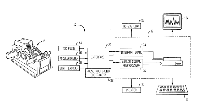
Figure 1 is a block diagram of the preferred embodiment of
the present invention.
Figure 2A is a block schematic diagram of the interface
circuit illustrate din Figure 1.
Figure 2B is a block schematic diagram of the analog signal
preprocessor circuit illustrated in Figure 1.
Z(~10097
-
Figure 3 is a chart describing the optimum processing steps
for analyzing various different types of mechanical vibrations.
Figure 4A-B is a flow chart describing the steps by which
the system analyzes signals and detects gear defects.
Figure ~A illustrates the steps by which analog sensor
signals are processed.
Figure 5B illustrates the steps by which the shaft encoder
pulses are detected.
Figure 6 illustrates a typical four gear/three shaft
reverted gear train.
Figure 7 is a graph of the vibration image produced over a
hunting tooth cycle for a single pair of meshing ears.
Figure 8A illustrates the effect of eliminating mo~ulation
induced signal components from a gear vibration pattern.
Figure 8B represents an algorithm for removing interfering
spectral components from a gear vibration image.
Figure 8C illustrates an example of a Discrete Fourir
Transform Vibration Image and shows the filtering regions
involved in 8B. ~
Figure 9A illustrates the effect of the removal of gear
defect signature contamination from an adjacent gear.
Figure 9B describes the gear pattern decontamination
process.
Figure 9C represents an algorithm for removing the
contribution of a defective tooth on a single gear from the gear
vibration images of other gears.
2010097
Figure lOA illustrates the effect of the removal of mesh
harmonics from the time domain vibration pattern.
Figure lOB illustrates that a signal is typically composed
of mesh harmonics, coherent noise and incoherent noise.
'-j Figure lOC illustrates the history of a gear tooth pattern
showing the increase of the defect over a period of time.
Figure lOD illustrates the amplitude history of an
individual defective tooth over a period of time.
Figure lOE illustrates the amplitude history of a non-
defective individual tooth over a period of time.
Figure 11 illustrates a history of a gear over approxi-
mately 100 hours from the initiation of cracking to the imminent
failure of the gear.
Figure 12A illustrates another four gear/three shaft gear
train.
Figure 12B illustrates the time domain vibration pattern
generated by gears A and B, and gears C and D and computed over a
single rotation of gears B and C.
Figure 12C illustrates the time domain vibration pattern
generated by gears A and B computed over the hunting tooth cycle
for A and B.
Figure 12D illustrates the time domain vibration pattern
generated by gears C and D computed over the hunting tooth cycle
for C and D.
Figure 12E illustrates a giant hunting tooth pattern
including the effects of gears A, B, C and D.
--~ 20~0097
Figure 12F illustrates the envelope of the giant hunting
tooth pattern illustrated in Figure 12D.
Figure 13 represents an algorithm for stacklng samples from
a periodic function given a rational non-integer number of
samples per period.
Figure 14 is a flow diagram indicating how the matrix of
collected data can be reduced and analyzed to generate different
sets and subsets of information.
During the course of this description like numbers will be
used to identify like elements according to the different figures
which illustrate the invention.
The basic invention 10 according to the preferred
embodiment is illustrated in Figure 1. A gear system 12 produced
a Top-Dead-Center (TDC) pulse 14 as well as inputs from
accelerometer 16 and shaft encoder 18 to interface 20. Pulse
multiplier electronics 22 can be used to speed up, i.e. multiply
the frequency of the pulses so that they can be processed by
microcomputer 32. The outputs of interface 20 provide inputs to
intercept board 24 and analog signal preprocessor board 26 which
are preferably housed within the chassis of microcomputer 32.
Microcomputer 32 preferably comprised an IBM-PC/AT 80286 type of
microprocessor which has connections to peripherals such as an
RS-232 communications link 28, a printer 30, a high resolution
color monitor 34 and keyboard 36.
~, ~o,J~ k
2010097
Interrupt board 24 is a commercially available device that
serves the purpose of notifying the microcomputer 32 that another
TDC pulse has arrived so that the microcomputer 32 can count the
number of encoder pulses to the next TDC pulse.
Inteface 20 is illustrated in detail in Figure 2A. The
input signal from accelerometer 16 passes through a high pass
filter 40 as channel A to the analog signal preprocessor 26. The
output from the shaft encoder 18 provides the input to low pass
deglitching filter 42 and Schmitt trigger 46 and from there to
analog preprocessor board 26. Likewise, the pinion TDC signal
input pulse 14 is stripped of its high frequency characteristic
by a low pass filter 44 and shaped by a Schmitt trigger 48 and
passed from there to the interrupt board 24. If the system 10
signals an imminent failure, a pulse is applied to pull up
circuit 50 which sounds an alarm. Jumper select switch 52
permits the user of the system 10 to route the raw accelerometer
signal 16 to channel B of the analog preprocessor board 26, or to
input a test signal generated by the D/A output on the analog
board 16.
The analog signal preprocessor circuit 26 i6 illustrated in
detail in Figure 2B. The incoming analog signal from the
interface circuit 20 input on channel A first passes through a
protection device 56 and relay 60 before it is amplified by the
first amplifier 62. A second relay 64 typically steers the
signal through an RC high pass filter 66 and a precision
rectifier 68 which outputs the signal through another relay 70.
Z010097
High pass RC filter 66 compensates for low frequency DC drift and
the first precision rectifier circuit 68 provides for full wave
rectification. In a minority of circumstances the relays 64 and
70 may be set to bypass the RC filter G6 and rectifier 68,
especially in those situations where low frequency drift is not
a problem or high frequency filtering might remove useful
information.
The output from relay 70 provides the input to relay 72
which has the option of steering the signal to either relay 74
or relay 86, both of which în turn have the option of steering
the signal to two separate directions respectively. Under most
circumstances, the signal will be directed through DC offset 88
to relay 90 and then to relay 84. Alternatively, relay ~6 could
bypass DC offset 88 and route the signal directly to relay 90.
It is also possible for input relay 72 to route the signal to
relay 74 where the signal could be directed either through RD-
high pass 82 or active high pass 76 and precision rectifier 78.
Relay 80 can then pass either of these ~ignals to relay 84.
Relay 84 passes its output signal through programmable low
pass filter 94 and a second amplifier 96 as an input to a 12 bit
analog/digital converter 102. An external sample clock input
from interface 20 is processed by clock logic 106 and forms a
second input to the 12 bit analog/digital converter 102.
Analog/digital converter 102 converts the analog input from
amplifier 96 into a digital form suitable for processing by
microcomputer 32. Data bus 100 programs the positions of Relays
X(J 10097
60, 64, 70, 72, 74, 80, 84, 86 and 90; the gain of amplifier 62,
the voltage offset of DC offset circuit 88, the cutoff frequency
of low pass filter 94, the gain of amplifier 96, and programs the
digital-to-analog converter device 104 whose output can be
jumpered through interface box 20. The analog signal
preprocessing circuit 26 also includes 8 test points TPl through
TP8 for the purpose of signal monitoring. The setting of relays
60, 64, 70, 72, 74, 80, 84, 86, and 90 depends upon the
conditioning that is required of the input signal prior to
processing by the microcomputer 32. This in turn depends upon
the characteristics of the input signal and the nature of the
system being monitored, for example, it could be gears, it could
be roller bearings, it could be a journal bearing, etc.
Baseboard processing of accelerometer signal 16 is identical
to the above discussion except that relay 60 is switched to
accept the output of protection device 58 which limits
accelerometer signal 16 on channel B input.
Gear defect analysis according to the present invention
involves processing vibration signals in a variety of ways to
optimize detection of specific defects. Figure 3 illustrates
that the detection of gear defects such as cracks and pitting
involves coherent processing of stress wave signals, whereas, for
example, monitoring for gear mesh noise or balance would
preferably rely upon band pass vibration information.
Figure 4A-B illustrates the steps in the preferred method
employed to detect and analyze incoming signals. These are
11
~ 2010097
steps that are performed by the elements described in Figures 1,
2A, and 2B.
The first step in the preferred method illustrated in Figure
4A-B comprises the detection and conditioning of the sensor
signals. As shown in Figure 5A, an off-the-shelf sensor 16
(typically a piezoelectric vibration sensor or acoustic
microphone sensor) mounted on or near the gear assembly 12 to be
monitored, would provide the input signal to the gear defect
analyzer system 10. Piezoelectric sensors 16 are often selected
to have a resonant freauency in the 20-60 KHz range and
therefore, band pass filters such as high pass filter 40 in
interface circuit 20 are used to pass frequencies centered on
those resonant frequencies. The system 10 is capable of
automatically alternating between two frequency bands (e.g. base
band and 40 KHz band) thereby providing additional diagnostic
information as well as providing information allowing for the
classification of the operating state (e.g. RPM and load) of the
gear assembly 12. The method for this is discussed in further
detail with reference to Figure 6 et sea. The incoming signal is
then passed through electronic full wave rectifiers, such as
precision rectifier 68 illustrated in Figure 2B and then through
low pass filters such as filter 94 to demodulate the signal in
order to extract its amplitude envelope, which is the signal
input to the analog/digital converter 102. The progression of
the signal from the piezoelectric sensor 16 to the analog-to-
digital converter 102 is illustrated schematically in Figure 5A.
12
ZC~10097
The shaft position encoder 18 can consist of a mounted gear
or reflecting surface such that a magnetic pick up 18 or optical
pick up produces a pulse for each angular increment of shaft
rotation. For example, as shown in Figure 5B, a gear with 120
teeth would produce a pulse every 3 degrees. The number of
pulses/turns often needs to be adjusted for proper gear mesh
monitoring. For example, 120 teeth could be adjusted to produce
160 pulses (4/3 x 120 = 160). For this a pulse multiplier/
divider phase lock loop circuit 22, as shown in Figure 1, is
used with the multiplier/divider integer ratio computer control.
A lock signal from the circuit 22 is also computer monitored to
insure that this output pulse rate is locked to shaft angle. As
a second check on the encoder pulses, a top dead center pulse is
often used so that the computer 32 can check that it has received
the proper number of samples/shaft turn pulses. A TDC pulse
(Top-Dead-Center pulse) is a once per shaft revolution pulse
whereas encoder pulses are multiple pulses per shaft revolution.
The TDC is needed for:
a.) a check that an encoder pulse was not missed. This is
important to the method. For example, computer 32
would verify that the proper number of encoder pulses
arrived for each TDC pulse.
b.) relating the vibration tooth images to a specific teeth
on the gear.
c.) to allow the test to be restarted and still have the
tooth images line up.
13
2~10097
d.) in general, a TDC pulse is used for both the input and
output ~shaft, allowing restarts to keep alignment on
the overall tooth-by-tooth time domain average.
The TDC pulse preferably comes from a reflecting surface attached
to the shaft such that light reflecting off the surface produces
one pulse per shaft revolution. Figure 5B illustrates the steps
employed by the system to produce digital ~sample clock pulses
from the shaft encoder mechanism 18.
The gear analyzer system 10 requires input parameters
identifying the number of teeth of each mating pair of gears and
the ratio of their shaft rotations to the shaft containing the
shaft encoder 10. With this information, the computer 32 can
then determine the number of shaft encoder pulses and f~actions
thereof for time domain averaging over one cycle of the overall
system, or one cycle of selected gear subsystems and/or one cycle
of a given shaft. This data represents the key parameters
required for performing shaft coherent time domain averaging
necessary to proceed to the next step. A stylized gear train is
illustrated in Figure 6 and is similar to the CRT display that
elicits the initial input parameter with regard to the number of
gear teeth and their relative ratios.
The sensor analog signal envelope illustrated at the bottom
of Figure 5A is digitized using an off-the-shelf 12 bit analog-
to-digital converter 102 with a digital sampling clock 106
controlled by the encoder pulses from shaft encoder 18. The
14
2~ 097
digital signal (e.g. base band and stress wave band selectable)is
then processed according to the next step.
~ The second step of the method illustrated in Figure 4A-~, is
to take the digitized vibration data and optimally time domain
average it over (1) one cycle of the overall gear system (2) one
cycle of selected gear subsystems, and (3) one cycle of a given
shaft of the system. Although computing the time domain average
for the complete gear system 12 is the most precise approach, it
may not be practical in some applications and the time domain
average for pairs of the gears (e.g. hunting tooth pattern for a
pair of gears) would serve as the next best approximation.
Figure 7 illustrates a hunting tooth vibration image which is
time domain averaged for a single gear pair.
In performing the above computations, two features of the
technique should be emphasized. Namely:
1. When the encoder 18 is not on one of the shafts of the
gear system 12 to be time domain averaged, an algorithm
(discussed below) which can average over non-integer sample
lengths and not cumulate errors is used.
2. The time domain averaging is "optimally" averaged (or
weighted) to take into account background noise level variations,
RPM and load vibrations.
The advantages of using the hunting tooth vibration pattern
analysis approach are discussed in more detail later on, but can
be summarized as follows:
-- Z~10097
1. It allows detection of anomalous vibrations produced by
individual pairs of meshing teeth (as shown in Figure 7 - only
when tooth number 8 of the pinion gear meshed with a limited set
of teeth (in the vicinity of Ring teeth 20-26) on the mating gear
did anomalous vibrations appear). This is only clearly
observable using the foregoing hunting tooth vibration analysis
approach.
2. By monitoring changes in vibration levels of individual
pairs of teeth over time, an accurate estimate of the remaining
interference due to background noise can be obtained. This is
critical in order to identify significant changes in the pattern
relating to identify defects.
3. Only through the use of the foregoing hunting tooth
pattern and the fourth step of the method, described
subsequently, can interference be removed from a given gear
vibration pattern due to a defect on its mating gear.
4. Only through the use of the hunting tooth gear pattern
can one of two gears on a given shaft, each of which mates with a
different gear, be identified as having the specific defect.
This technique involves detecting which hunting tooth pattern
contains a modulation attributed to the gear defect meshing rate.
See Step 8 described in further detail subsequently.
The third step in the method is to classify the system
state. Based upon signal characteristics (e.g. the baseband
spectrum mean, variance and/or shape) the operating state of a
gear system (e.g. constancy and relative level of load and RPM)
16
2~10097
can be monitored such that measures of gear condition (computed
from baseband or stress wave band) over time can be compared with
a given operating state.
Such a procedure is required for machinery used under
variable operating conditions so that changes in the time domain
gear vibration pattern due to gear defects can be reliably
distinguished from significant changes in gear meshing dynamics.
The foregoing procedures can be generalized for many other
applications where specific characteristics of the sensor signal
can define the operating state of a system so that other aspects
of that signal can be analyzed for estimates of machine component
condition status.
The fourth step in the system as illustrated in Figure 4A-B
is the elimination of modulation interference. Shaft runout,
gear pitch cycle runout, and other factors can cause gear mesh
loading vibrations which can induce vibration amplitude and phase
modulation that interferes with the time domain pattern computed
in Step No. 2. It is therefore necessary to automatically
identify the spectral components containing this interference and
minimize their effect. The technique employed according to the
present invention involves computing Discrete Fourier Transforms
(not FFT's) of the vibration pattern, modeling the overall
spectral background form, and then use detection criteria to
identify undesirable characteristics of the spectrum, which are
then filtered out. The amplitudes of those characteristics are
stored for analysis for other system defects (e.g. U-joints,
17
-- 2~10097
bearings, balance, etc.) relating to the same source of
modulation. Figure 8A illustrates an example of the
effectiveness of this procedure, outlined in Figures 8B and 8C.
Step No. 5 of the method illustrated in Figure 4A-b
comprises a process for gear vibration pattern decontamination.
A significant defect on one gear can induce interference on the
vibration pattern of its mating gear, the magnitude which depends
on the specific tooth ratios involved. Figure 9A illustrates an
example of such a decontamination process for removing the
interference caused by a defect on a 9 tooth pinion gear from the
vibration pattern of its mating 39 tooth ring gear. By
eliminating, from the hunting tooth pattern, the contribution of
those pairs of meshing teeth that only include the defective
pinion tooth, the ring gear vibration pattern can then be
computed with this interference removed. Figure 9B illustrates
the generalized schematic steps for this process outlined in
Figure 9C. Defects on tooth i of a gear A, which are apparent in
the coherent stack for gear A, also tend to affect the coherent
stack for other gears, e.g., gear B. The distorting or leakage
effect of tooth 1 of gear A can be eliminated from the coherent
stack of gear B by simply eliminating all data for tooth i of
gear B before doing the stack for gear B. Linear processors such
as spectral filtering, etc. would not be as effective since the
vibration produced by the defective tooth is a highly non-linear
function of which ring tooth it meshes with.
18
2C~0~)97
The ~ystem 10 then has a choice of parallel, alternative
steps. Step 6A mea6ures defects from gear time domaln averages.
From the tlme domain average computed over one cycle of a given
shaft the given "peak residual ratio" ls computed as follows:
PRR s IRl f~e~ R
where
/R/~ = peak absolute value of vibration image with DC
first, second, and any lnterfering mesh harmonlcs
removed
= standard deviation of resldual pattern
= standard deviation of vibratlon lmage with DC,
flrst, second, and any mesh lnterferlng Harmonlcs
removed
This measure is very effective at detecting a change in the
pattern which is localized and lndicative of a fault somewhere ln
the gear. See Flgure l~A.
Another measure which complements the foregoing measurement
is the non-mesh energy ratio (NMR) corrected for incoherent noise
and 1~ good for detecting overall deterioratlon of vlbration
images due to problems like multiple tooth pitting.
This measure ie computer as follows:
NMR ~ ( ~ 7~Z ~Z ~ ~m ~)
6~z ~ ~ ~ Z >
where
19
2~10097
= variance of vlbration image
Z = variance of mesh harmonics
Z = varlance of lncoherent noise estimate (spectral
technique requlred for computing parameter)
All of the foregoing parameters have the DC, first and
second, and any lnterfering mesh harmonics removed.
Step 6B illustrated in Flgure 4A-B is an lndividual tooth
based analysls of gear condltlons. By computlng one or more
measures (e.g. lndivldual amplitude) of the lndivldual tooth
vibration pattern, or the vlbration pattern for an individual
tooth pair (containing a hunting tooth pattern), and tracing the
variation of this measure (variance, movlng average based
changes, transient behavlor, etc.) over time, reliable
indications of fault development can be obtained. Figure loC
illustrates such a sequence of gear tooth patterns terminatlng
in the clear anomalous behavior of one tooth which correlates
with lts being cracked. Flgure lOD illustrates the amplitude,
in another case history, of a given tooth over time as it
approaches failure. The bottom plot in ~igure lOE shows a tooth
history for the adjacent tooth with respect to the flgure above,
which does not have dramatic changes therein.
The spectral components induced by gear modulation effects
which were removed from the gear stock often contain useful
information. For example, 60me bearing problems lead to a
additive first harmonic spectral component in contrast to a
multiplicative effect produced by gear runout on defective
2010097
Universal joints can lead to large second harmonic components.
In Step 6C of Figure 4A-B, the amplitude of these spectral
components are tracked over time.
The seventh step comprises the performance of analysis of
the time histories of a given gear conditioned measured within a
given system operating state. The measure of gear tooth
conditions computed from the gear vibration pattern in the sixth
step above are traced over time and shown in Figure 11 (with the
exception of the results of Step 6B which is already in the form
of a feature history). The significant changes in such a plot
are automatically detected by computer 32 and an alert is sounded
through the pull up circuit 50 and alarm illustrated in Figure
2A. According to Figure 11, the beginning of crack generation
appears early in the test giving the operator warning for test
purposes, quality control inspection or preventive maintenance.
Towards the end of the plot the strong rise gives warning of
imminent failure. A wide variety of methods to analyze the
foregoing and provide threshold warnings from the plot history
can be employed. Simple amplitude thresholds that require the
curve to exceed a preset level for a preset period of time can be
employed to trigger appropriate warnings.
The eighth step in the process is illustrated in Figures
12A-12E. Figure 12B illustrates the vibration pattern over a
rotation of the BC shaft. The question i6 - how does one
determine which gear, B or C, has the defect? According to the
steps of the method illustrated in Figures 12C and 12D, the
21
Z6~10097
-
hunting tooth pattern for the A/B mesh is illustrated in Figure
12C and the hunting tooth pattern for the C/D mesh is illustrated
in Figures 12D. The variance of the tooth defect for the HTAB is
much greater than the variance of tooth defect of HTCD. Hence
the defect lies on gear B.
Alternatively, another method can be employed as illustrated
in Figures 12E and 12F. According to the steps of the method
illustrated in Figures 12D and 12E, a giant hunting tooth
pattern HTABCD~ i.e., the time for cycling all four gears, A, B,
C, and D is employed. The envelope of the defect, which is
extracted as illustrated in Figure 12F provides the basic
information. The strong component at the period of HTABor HTCD
means that the defect is on gear B or gear C respectively
The ninth step, illustrated in Figure 4, is to produce a
status report on the different components and/or sound an alarm
or otherwise shut down the monitoring system and/or perform and
display the results of the analysis on monitor 34.
~ igure 13 illustrates an algorithm employed for stacking
samples from a periodic function given a rational non-integer
number of samples per period. The flow chart depicts an
algorithm for real-time execution of a microcomputer such as 32.
The algorithm is to be entered repeatedly, once per incoming data
sample, until NSTK, the count of elapsed period, reaches the
desired value, MAXSTK. As used in the algorithm, the following
items have the following meanings.
22
201 0097
N,D - The ratio N/D expresses fractional part of the
number of samples per period, reduced to lowest
terms, i.e., there are no common factors of N and
D.
STXLEN - The length of the stac~ to be accumulated for the
periodic function. STKLEN is the largest integer
less than or equal to the number of samples per
period.
RESID - A residual placeholder, initially zero.
BUF - A buffer of length STXLENfl, initially all zeros,
in which the stack will be accumulated.
INDEX - An index into the elements of BUF, initially zero.
NSTK - Count of elapsed periods, initially zero.
MAXSTX - Number of elapsed periods desired in the stac~.
DATA - The latest sample of the incoming data stream.
The total matrix of data illustrated in Figure 14 is
necessary to determine larger patterns such as the giant hunting
tooth pattern. Reduced sets of data from the total matrix can be
used to obtain a submatrix to detect a single hunting tooth pair of
gears and that submatrix can be further reduced to a smaller single
gear data matrix to produce a single gear image.
2-3
.1
21~10097
The advantages of the foregoing system 10 include the
following.
1. The system 10 produces a vibration based image of
individual gear teeth in operating machinery which reveal
important aspects of their conditions.
2. The system 10 provides an automatic measure of the
quality (e.g. signal to noise ratio) of the gear image to aid in
interpretation.
3. The system 10 detects, ~uantifies, classifies,
automatically analyzes gear images evolving over time and can
also forecast gear problems, and display any of this information
to the operator.
4. The system 10 utilizes novel methods to detect,
evaluate, and eliminate interfering spectral contributions.
5. The system 10 utilizes novel deconvolution techniques
to remove leakage of images of adjacent gears which are normally
present in standard synchronous gear imaging.
6. The system 10 can produce a hunting tooth gear image in
order to interpret gear tooth status. This technique is
especially effective for interpreting tooth-to-tooth specific
interaction.
7. The system 10 utilizes selectable frequency bands, shaft
synchronized coherent processing, sensors attachable outside the
equipment and automatically compensates for variable operating
speeds (i.e. it is shaft synchronized).
24
2(~1Q097
8. In the system 10 only, a single shaft of a multiple
shaft gear train need be synchronized for all of the gear images
to be produced.
9. The system 10 can perform a stack of data where the
number of samples per stack period is an irrational number (not
an integer).
10. The system 10 includes a means and method to detect
which gear of a multiple gear shaft has the defect and further,
it includes the means to automatically separate mesh patterns.
11. The system 10 permits in-process operator controlled
analysis through Discrete Fourier Transform, FFT, specialized
filtering and references to other data.
12. Analog preprocessing of the signal is automatically set
up through the use of a computer-controlled analog board with a
variety of programmable functions including shaft synchronized
A/D and a D/A for self-calibration and system checks.
13. The system 10 can be implemented using an off-the-shelf
high speed microcomputer.
14. The system 10 produces data regarding the condition of
other moving interactions including U-joints, pinion bearings,
and ring bearings when applied to the testing of axles.
15. The system 10 utilizes pulse multiplier boards to
enable operation from shaft encoders which give too few or too
many pulses per shaft turn.
16. The syste~ 10 provides other functions in that it
detects, quantifies, and classifies quality of machinery based on
2~10097
-
mesh harmonic amplitude vs. RPM measurements. This feature is
important for the testing of quality control of transmissions and
the like and i6 currently not believed to be performed because
of the cost required for the computer analysis. The present
system 10 allows all such information to be obtained through the
use of relatively inexpensive PC-AT type microcomputers 32 and an
appropriate analog preprocessing board which includes a low pass
tracking filter.
While the invention has been described with reference to the
preferred embodiment thereof, it will be appreciated by those of
ordinary skill in the art that various modifications and changes
can be made to the parts and steps which comprise the invention
without departing from the spirit and scope thereof as a whole.
26