Note: Descriptions are shown in the official language in which they were submitted.
-1- Rc~ as,4a7
1
ELECTRON GUN ASSEMBLY FOR A CRT
The present invention relates to an
6
electron gun assembly for a cathode-ray tube
(CRT) and, more particularly, to a structure for
ZO strengthening the sidewall of a cup-shaped member of
an inline assembly for a plural beam CRT.
The electrode members of an inline electron gun
assembly are serially arranged to accelerate and focus a
plurality of electron beams along spaced, co-planar
electron beam paths. The electrode members of the gun
assembly are mechanically secured by means of attachment
tabs and studs to at least a pair of insulative support
rods which extend along the beam paths. Each of the
electrode members commonly has several spatially-related
apertures formed therein to accommodate the respective
electron beams generated within the electron gun
assembly. It is important that these several apertures
be accurately located and aligned relative to the related
apertures in adjacent electrode members, and to the
respective electron generating surfaces. During the
fabrication of the electron gun assembly, the attachment
tabs and studs of the various electrode members are
embedded into the temporarily heat-softened insulative
support rods, at which time the support rods on opposed
sides of the gun assembly are pressured inwardly toward
the electrode members to force the attachment tabs and
studs into the support rods. The compressive pressure
tends to exert a distorting force upon the several deep-
drawn, cup-shaped electrode members which comprise the
main focus lens of the electron gun assembly.
Most experience to date.raith conventional deep-
drawn, cup-shaped electrodes, having sidewalls up to
9
-2- RCA 85,427
1 about 12.7 mm long, shows that these electrodes tend to
develop a negative or concave ~~oil-canning~~ tendency:
i.e., the sidewall of the electrode tends to bow inwardly
toward the electron beam axes. When studs are welded to
opposite sides of the sidewall of such electrodes, exact
positioning and welding are difficult because of the
variable slope and degree of negative ~~oil-canning~~ that
occurs.
An even greater problem has been encountered in
electron guns in which ultra-deep drawn, cup--shaped
electrodes have sidewalls more than 12.7 mm long. In
such ultra--deep drawn electrodes, a critical thinning of
the sidewall occurs. The apex of the ~~oil-canning~~ in
these electrodes occurs about 10.16 mm from the support
flange located at the open end of the electrode. In the
vicinity of the apex, the sidewall thins from the desired
thickness of about 0.25 ram to about 0.19 mm. If the
~~oil-canning~~ is negative or concave on both sides of the
sidewalk the problem of stud positioning is similar to
that of the shorter deep-drawn electrodes described
above: however, if the ~~oil-canning~~ of one side of the
sidewall is positive or convex and the other side is
negative or concave, or if both sides exhibit positive or
convex ~~oi1-canning,~~a new phenomenon occurs. During the
beading ope~ration,in which the insulative su
pport rods
ate heated to a molten state and formed into contact with
the attachment tabs and studs of the electron gun, the
positive or convex ~~oil-canning~~ sidewall is forced
inward by the stud attached to the sidewall of the
previously convex surface.
The inward displacement of the previously convex
sidewall acts like a loaded spring. As soon as the arms
of the beading apparatus retract at the end of the
beading cycle, the compressed sidewall of the electrode
tends to return to its previous convex position forcing
the insulative support rods, which ate still in a plasc.ic
state, to bulge outwardly. Shear forces are thereby
RCA 85.427
- 1 introduced into the insulative support rods during the
Gaoling-deflection cycle,causing the support rods to
crack in the vicinity of the attachment tabs or studs.
Even in electron guns in which the stress forces
are not sufficiently great to crack the support sods, the
varying degree of ~~oil-canning~~ of the sidewalls can
cause a side-to-side displacement or offset of the
ultra-deep drawn electrode relative to the other
electrode members of the main focus lens..This results in
a change of aperture locations relative to those in the
adjacent electrode members, thereby producing deleterious
inter-electrode spacing relationships and distortion in
the electron beam trajectories.
U,S. Pat. No. 4,484.102, issued to J. R. Hale on
Nov. 20, 1984, discloses a structure for strengthening
the sidewall of a conventional deep-drawn electrode. The
structure described therein comprises a wedge-shaped
shoulder that is formed in opposite parallel sides of the
sidewall of a deep-drawn substantially rectangular
cup-shaped member. The wedge-shaped shoulder projects
outwardly at an acute angle of about 45 degrees from the
sidewall arid extends into the supporting flange of the
electrade adjacent to the attachment tabs. This
structure is insufficient to prevent flexure of the
sidewall of ultra-deep drawn electrodes.
U.S. Pat No. 4,595.858, issued to J. R. Hale on
Jun. 17, 1986, discloses a structure suitable for
reinforcing either deep-drawn or ultra-.deep drawn
electrodes. A pair of reinforcing ribs are formed into
each of the opposed parallel sides of the sidewall of the
electrode to minimize flexure of the opposed sides in the
vicinity of the studs, which are attached to the sidewall
and embedded into the glass support rods, so as to
minimize deleterious displacement, i.e.. ~~oil-canning" of
the electrode. However, the reinforcing ribs formed in
the sidewall do nothing to provide a flat welding surface
for the studs. Accordingly, a structure is desired which
~o~o~ss
-4- RCA 85.427
1 simultaneously strengthens the sidewall of the electrode
while providing a flat surface for attachment of the
studs.
In accordance with the invention, an electron
gun assembly for a cathode-ray tube
includes a plurality of electrodes longitudinally spaced
along and attached to a plurality of insulative support
means. The electrodes include at least one substantially
cup-shaped member having a base portion at one end, a
supporting flange portion substantially parallel to said
base portion at the oppositely disposed other end,and a
sidewall extending therebetween. Attachment means are
secured to the sidewall to facilitate attaching the
cup-shaped member to the insulative support means. The
cup-shaped member is improved by foraging therein
strengthening means for providing a substantially flat
welding surface having structural rigidity for securing
the attachment means thereto.
In the drawings:
FIG. 1 is a partial broken-away side elevational
view of an electron gun assembly incorporating a novel
cup-shaped electrode having. strengthening means.
FIG. 2 is a front elevational view of the novel
electrode of FIG. 1.
FIG. 3 is a partially broken-away side elevational
view of the novel electrode.
FIG. 1 shows structural details of an improved
six-electrode inline electron gun assembly 10 centrally
mounted in the neck 11 of a cathode-ray tube (CRT)13.
The CRT 13 includes an evacuated envelope (mainly not shw.~,:w
~~6~6
-5- RCA 85.427
1 closed at the neck end by a glass stem 15 having a
plurality of leads or pins 17 extending therethrough. A
faceplate (not shown),having a viewing screen, closes the
other end of the envelope. A funnel (not shown) extends
between the faceplate and the neck 11 of the envelope.
The inline electron gun assembly 10 is designed to
generate and focus three electron beams along spaced.
co-planar convergent beam paths having a common,
generally longitudinal direction toward the viewing
screen. The gun assembly 10 comprises two insulative
support means 23 which are preferably glass support rods
from which the various components are supported to form a
coherent unit in a manner commonly used in the art.
These components include three substantially equally
transversely-spaced, co-planar cathodes 25 (one for
producing each beam), a first electrode 27 (also referred
to as G1), a second electrode 29 (also referred to as
G2), a third electrode 31 (also referred to as G3), a
fourth electrode 33 (also referred to as G4), a fifth
electrode 35 (also referred to as G5), a sixth electrode
37 (also referred to as G6), and a shield cup 39,
longitudinally-spaced, in that order, along the support
rods 23.
The electrodes 35 and 37 form the main focusing
lens of the electron gun assembly 10. The various
electrodes of the gun assembly 10 are electrically
connected to the pins 17 either directly or through metal
ribbons 41. The gun assembly 10 is held in a
predetermined position in the neck 11 on the pins l7,and
with snubbers 43 on the shield cu 39 which
p press-on and
make contact with an electrically conductive coating 45
on the inside surface of the neck 11. The conductive
coating 45 extends over the inside surface of the funnel
and is connected to an anode button (not shown). A
conventional Better assembly (also not shown) is attached
at one end to the cup 39 and extends in cantilevez
fashion in the funnel of the envelope.
~~~osss
RCA 85;427
1 The G5 electrode 35 comprises a focus electrode as
does the G3 electrode 31 which is electrically connected
to the G5 electrode. The electrode 35 comprises
first and second substantially rectangular cup-shaped
members 47 and 49, respectively. The cup-shaped members
are joined together at their open ends. The first .
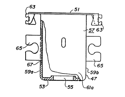
cup-shaped member 47 is shown in FIGS. 2 and 3. The
cup-shaped member 47 is a deep-drawn part comprising a
supporting flange portion 5l, located at the open end, and
a base portion 53 at the opposite end. The base portion
53 is substantially parallel to the supporting flange
portion 51. Three inline apertures 55 are formed through
the base portion 53, although only one aperture is shown
in FIG 3. A sidewall 57, having substantially parallel
opposed sides 59a and 59b and opposed end portions 61a
and 61b, extends between the supporting flange portions
51 and the base portion 53 of the cup-shaped member 47.
A plurality of attachment tabs 63 are formed in the
supporting flange portion 51 adjacent to the opposite
sides 59a and 59b of the sidewall 57 to facilitate
attachment of the cup-shaped member 47 to the glass
support rods 23. As shown in FIGS 1 and 3, a pair of
studs 65 are attached to the sidewall 57 of the
cup-shaped member 47, one stud to each of the opposed
sides 59a and 59b. The studs 65 and the attachment tabs
63 are embedded into the support rods 23. As described
above, deep-drawn electrodes, such as the cup-shaped
member 47, have a tendency to ~~oil-cane, i.e., bow either
inwardly or outwardly, unless the sidewall is
strengthened. One means of strengthening or reinforcing
the sidewall is described in the abovementioned U.S. Pat
No. 4,595,858. In that patent, as discussed above, a pair
of reinforcing ribs are formed into each of the opposed
sides of the sidewall. However, the reinforcing ribs do
not rovide a flat su
p pport surface for attaching the
studs to the sidewalk with the result that some
side-to-side displacement or offset of the deep-drawn
~~1~~~6
-7- RCA 85.427
1 electrode occurs relative to the other electrodes of the
electron gun. This provides some distortion in electron
beam trajectories.
The present invention addresses both the problem
of strengthening the opposed sides 59a and 59b of the
sidewall 57 of the deep-drawn cup-shaped member 47, as well
as that of providing a flat, geometrically consistent
welding surface for the attachment of the studs 65. A
coined welding area 67 is formed in each of the opposed
sides 59a and 59b of the sidewall 47. The coined area 67
is centrally located in each of the opposed sides 59a and
59b. and is slightly larger in size than the studs 63 to
permit the studs to be located within an innermost
portion 69 of the coined area. 'Coining". as is known in
the art, is the process of forming metal by squeezing
between two dies so as to impress a well-defined imprint
on one of both surfaces. kith the cup-shaped electrode
member 47 positioned on the last extruding die (not
shown), a pair of dies (also not shown) contact the
opposed sides 59a and 59b to s ueeze the
q portions 67 of
the sidewall therebetween to imprint the substantially
flat, geometrically consistent welding surface 69
therein. The "coining" work-hardens and strengthens the
affected portions of the sidewall 57, while providing
substantially flat welding surfaces for the attachment of
the studs 65. The coined area 67 is shown in FIG 3 as
formed only in the exterior surface of the side 59a. An
inward projection of the coined area can be achieved by _
having a mating recess formed in an inner die: however.
the present structure is cost effective and provides the
necessary structural strength of rigidity and flatness.