Note: Descriptions are shown in the official language in which they were submitted.
~B~
MELT BLOWIN~ DIE
FIELD OF THE INVENTION
1This invention relates to the melt blowing of thermo-
plastic fibers, and more particularly to an improved melt blowing
die.
BACKGROUND OF THE INVENTION
5Melt blowing is a process for manufacturing nonwoven
products by extruding molten thermoplastic resin through fine
capillary holes (orifices) and blowing hot air on each side of the
extruded fibers to attenuate and draw down the fibers. The fibers
are collected on a screen or other suitable collection device as a
random entangled nonwoven web. The web may be withdrawn and
further processed into consumer goods such as mats, fabrics,
webbing, filters, battery separators, and the like.
Because of the extreme precision required in machining the
orifices and flow passages, a key portion of the die, frequently
referred to as the die tip, is separately manufactured using high
quality steel. The die tip is then assembled into the die body.
The die tip is an elongate member having a nose piece of
triangular cross section. The orifices are drilled in the tip of
the triangular apex and communicate with an internal flow channel
formed in the die tip.
A serious problem associated with die tips of this
construction is the reduced mechanical strength in the apex region
of the die tip. The orifices, in combination with the internal
flow channel, creates a weakness in the apex region of the struc-
ture because of the reduced cross sectional area of steel in thisregion. The high internal pressures caused by extruding the
molten resin through the tiny orifices frequently causes the
nosepiece to fail in tension at the apex. This problem
was identified in U.S. Patent 4,486,161 which teaches the use of
integral tie bars spanning the die tip flow channel. This
reference also discloses (Fig. 2) the use of bolts and spacers
ao ~ ~ 8 ~ Q
across the flow channel.
SUMMARY OF THE INYENTION
The present invention reduces the tendency of the
nosepiece to fail by providing a construction which results in
residual compressive forces and stresses in the apex region of the
nosepiece when assembled. The residual stresses counteract the
internal fluid pressure so that the net forces tending to split
the apex region are reduced or eliminated.
The die tip is adapted to be mounted on a surface formed
in the die body and bolted in place. !nternal shoulders formed on
opposite edge portions of the mounting surface engage opposite
longitudinal edge portions of the die tip with the bottom of the
die spaced slightly from the confronting mounting surface. Upon
bolting the die tip to the die body, opposite and equal bending
moments about the shoulders (acting as fulcrums) are created.
These bending moments oppose each other in the nosepiece apex
region resulting in compressive stress in that region.- Thus, upon
pressurizing the die tip flow channel, the internal fluid
pressures are counteracted by the compressive forces in the apex
region. This reduces the tensile forces imposed in the apex
region.
The die tip, or a component thereof, must contact the die
body to provide a fluid seal for molten polymer to flow from die
body passages to the die tip flow channel. The shoulders must be
sized in relation to the contacting seal surfaces of the die tip
and the mounting surface to provide sufficient fluid seal contact~nd yet retain the residual compressive forces in the apex region.
Other mounting configurations are possible for achieving
compressive stress in the apex region. The principle involved in
the present invention relies on creating opposite and equal
bending moments about the longitudinal edge portions of the die
tip which are at least in part resisted~by opposite and equal
forces imposed at the apex region.
Applicant's copending International Publication No. WO87/04195
published July 16, 1987, discloses a melt blowing die but
~ n3~ ~ ~ 6 Q
does not disclose the novel feature of the present invention. It is importarlt to note
that the published PCT Application does not disclose a die tip having compressive
forces imposed in the apex region thereof. In fact, the structure disclosed in Figures 2
and 3 of WO87/04195 would impose opposite bending moments thereby resulting in
tensile stresses in the apex region which could, weaken the nosepiece.
BRI~F DESCRIPTIO~ OF THE DRAWINGS
Figure 1 is a schematic illustrating the main components
of a melt blowing line.
Figure 2 is a perspective view of a die tip constructed
according to the present invention.
Figure 3 is a cross-sectional view of a meltblowing die
il~ustrating the die tip of Figure 2 mounted on the die body.
Figure 4 is a force diagram of the die tip as mounted on
the die body illustrating the bending moments imposed on the die
tip.
DESCRIPTION OF THE PREFERRED EMBODIMENTS
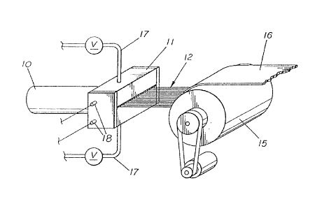
A melt blown line is illustrated in Figure 1 as
comprising an extruder 10, melt blowing die 11 and a rotating
collector drum or screen 15. Extruder 10 delivers molten resin to
the die 11 which extrudes side-by-side fibers into converging hot
air streams. The air streams attenuate and draw the fibers down
forming air/fiber stream 12. The fibers are collected on screen
15 and are withdrawn as a web 16. The typical melt blowing line
will also include an air source connected to the die 11 through
valved lines 17 and heating elements 18.
As shown in Figure 3, the die 11 includes body 20, an
elongate die tip 22 secured to the die body 20, and air plates 23
and 24. For purposes of this invention, the die body 20 is
constructed in die halves 27 and 28 (including parts 27a and 28a)
which, when assembled, form the die body 20. Details of the die
body assemblage are not illustrated. However, the assemblage of
' ~
8 ~ ~
- 4 -
these pa~ts may be by bolts as disclosed in WO87/04195.
As best seen in Figure 2, the die tip 22 includes
outwardly extending nose piece 29 of triangular cross section and
flanking flanges 25 and 26. The nose piece 29 terminates in -apex
region 30. The included angle of the taper of the nose piece 29
generally ranges from 45 to 90 degrees. A central elohgate
channel 31 is formed in the die tip 22. A plurality of s-idè-by-
side orifices 32 are drilled in the apex region 30 and are in
fluid communication with channel 31. The apex region 30 of the
nosepiece 29 is the tip portion which contains the orifices 32.
The orifices are distributed along knife edge apex 30a of the
nosepiece 29, with from 10 to 40 orifices per inch being generally
provided. The orifices 32 are generally 0.010 to 0.025 inches in
diameter.
The interior side of the die tip 22 includes flat
surface 35 and longitudinal notches 36 and 37 (see Fig. 2)
flanking surface 35. For purposes of defining the spacial
relationship of die tip parts to the die body, the term "interior"
refers to die tip parts adjacent the die body. A longitudinal
groove 38 is formed in a central portion of die body surface 35
and at the inlet of channel 31. As shown in Figure 3, generally
flat flow distribution member 39 (referred to as a breaker plate~
is mounted in groove 38. The internal part of the breaker plate
39 is perforated to permit passage of molten resin when mounted in
groove 38. The breaker plate 39 protrudes slightly beyond surface
35 and is provided with flat surface 41. The longitudinal outer
edge portions of surface 41 of the breaker plate 39 engage the die
body and as described below forms a fluid seal therewith. For pur-
poses of this invention, the breaker plate 39 is considered to be
a part of the die tip 22. In some die constructions, however, it
may not be necessary to provide a breaker plate 39. In such
constructions, the groove 38 would not be needed and embossed
strips (illustrated in Figure 4) flanking the channel 31 and
protruding outwardly from surface 35 could serve as the seal
' ~2
,
1 surface on the body 20. ~ ' - '
The die body 20, which is generally fabricated from high
quality steel in symmetrical halves and bolted together, has
formed therein a groove defined by sidewalls 42 and 43 and bottom
surface 44. Also formed at longitudinal edge portion's of the
surface 44 are parallel shoulders 46 and 47 which are sized to
mate with parallel notches 36 and 37 of the die tip 22.' Shoulders - - '
46 and 47 provide the mounting support means for the di'e tip 22.
Note that the shoulders 46 and 47, in addition to supporting edge
portions of the die tip, in the direction of bolt' force ('described
below), also prevent lateral expansion or movement of of the die
tip base.
A coat hanger flow passage 33 terminates in cavity 34 in
a central portion of surface 44. Cavity 34 extends substantially
the full length of the die and serves to distribute molten polymer
therealong and deliver polymer to channel 31 through breaker'plate
39.
The die body 20 also includes air conduits 48 and 49 for
delivering air to opposite sides of the die tip 22. The air
plates 23 and 24 in combination with the die tip 22 define
converging air flow passages 51 and 52. Converging air streams
discharge at the knife edge 30a of the nosepiece 29 and contact
fibers of molten resin extruded from orifices 32. The air streams
attenuate and draw the fibers down forming air/fiber streams
illustrated by reference numeral 12 in Figures 1 and 3.
As best seen in Figure 2, the die tip flanges 25 and 26
are each provided with a set of aligned bolt holes 53 and 54.
Bolt holes 53 and 54 are, respectively, aligned on opposite sides
of nose piece 29 and the outer ends of each are counterbored at
53a and 54a.
Returning to Figure 3, the die tip 22 fits in die body
~0 with the shoulders 46 and 47 receiving the complementary shaped
die notches 36 and 37.
The die body 20 has formed therein two sets of aligned
threaded bolt holes 56 and 57 which open to and are spaced
2Q~G~
1 along surface 44. The bolt holes 56 and 57 are aligned, respec-
tively, with die tip holes 53 and 54. Bolts 58 and 59 extend
through holes 53 and 54 of die tip 22 and are threaded to holes 56
and 57 thereby securing the die tip 22 to body 20. The bolt heads
58a and 59a fit in counterbores 53a and 54a. - ~ - - ~
With the breaker plate 39 mounted in groove 38, die tip ~ - -
22 is positioned on shoulders 46 and 47 of the die body 20. The
bottom surface 41 of breaker plate 39 confronts a portion of
surface 44 surrounding cavity 34. With the die tip 22 positioned
on the shoulders 46 and 47, but not bolted, the die tip surface 35
is spaced from die body surface 44 and breaker plate surface 41 is
spaced from die body surface 44. The unstressed spacing (51)
between surfaces 35 and 44 is greater than the unstressed spacing
(S2) between surfaces 41 and 44. In order to provide the fluid
seal for polymer flowing from cavity 34 to channel 31, S2 is 0
in the bolted position of die tip 22. The following are the pre-
ferred spacing S1 and 52:
Die Tip Positioned Die Tip
But Not Bolted Bolted
S1 from 0.005 to 0.030 milsfrom 0.004 to 0.029 mls (avg.)
52 from 0.001 to 0.010 mils 0
Sl > S2
F~om the above, it is apparent that S2 (not bolted) equals S
(not bo~ted) minus S1(bolted).
It should be noted that the spacing between surfaces 41
and 44 are measured with the breaker plate 3g fully mounted in
groove 38. In practice, the plate 39 may engage surface 41
leaving the space between the inner surface of plate 39 and the
bottom of groove 38. As will be appreciated from the following
description, the spacing may be at either location.
Upon tightening of bolts 58 and 59, opposite bending
moments are imparted on the die tip 22 about shoulders 46 and 47,
which act as fulcrums. Bolts 58 create a bending moment in the
clockwise direction as viewed in ~igure 3 and bolts 59 create a
counterclockwise bending moment. These bending forces, being
. ~L~
1 in opposite directions, concentrate in the apex r~gion-'30-of the
die tip 29. Continued torquing of bolts 58 and 59 causes the '
surface 41 to sealingly contact surface 44 providing a fluid seal
for polymer flow from cavity 34 to channel 31. Note that the
bolting force causes plate 39 to fully seat in groove 38 (regard-
less of its starting position) and form a seal therewith. ' ' - '
The force diagram of Figure 4 depicts the mounting
forces imposed on the die tip 22. The bending moments'created by
bolt Forces F, F' about fulcrums A,A' create opposite and equal
forces B, B' in the apex region 30 and forces C,C' in the fluid
seal regions. At least a portion of the forces B, B' are'created
prior to creation of forces C,C'. The opposite and equal forces
B and B' create compressive forces which are maintained with the
die tip 22 bolted to body 20. These compressive forces counteract
fluid pressure forces within channel 31. Although the forces B
and B' may vary within wide ranges, depending on several factors,
they should be sufficient to create compressive stress of at least
1,000 psi, preferably at least 10,000 psi, and most preferably at
least 20,000 psi in the apex region 30 (i.e. the area of metal in
a plane passing through the axes of the orifices 32). The greater
S2, the greater the compressive stress. S2 of 0.002 to 0.005
are preferred.
An important feature of the die constructed according to
the present invention is the means for mounting the die tip 22 on
the die body which creates compressive forces in the apex region
30. This is achieved by supporting edge portions of the die tip
22 on the die body so that opposite and equal bending moments are
imposed on the nose piece 29. When the bolts 58 and 59 are fully
torqued a residual compressive stress is created in the apex
region 30 and a compressive seal force is created at the junction
of surfaces 41 and 44. Other structures for creating the bending
moments are possible. For example edge projections in the die tip
(in place of the notches 36 and 37) could engage surface 44
(without shoulders 46 and 47) thereby providing 51 > S2 In
other constructions, it is possible to create the residual
- 8 - ~ ~ ~E~t~
1 compressive forces in the apex region where Sl = S2 (unstressed).
With the die tip 22 bolted to the die body, mol-ten
polymer flows through passages 33, 34, plate 39, channel 31, and
orifices 32, while hot air flows through air passage 48, ~1, and - : -
passage 49 and 52, discharging as sheets on opposite sides of the ,
nosepiece apex 30a. As described above, the internal pressure in ~-
the apex region 30 is counteracted in part by the compressive
forces imparted by the opposite bending moments concentrated on
that region.
Although the present invention has been described with
reference to the preferred embodiment, it will be appreciated that
variations are possible without departing from the inventive
concept described and claimed herein.