Note: Descriptions are shown in the official language in which they were submitted.
201 1200
CORD LOCK DEVICE
Field of the Invention
This invention relates to a cord lock device and more
particularly a cord lock device adapted for incorporation into
wearing apparel such as a cuff and in operative association with
a piece of cord which when selectively pulled will substantially
close the cuff so as to protect the wearer against unfavourable
environmental elements.
Backqround of the Invention
Wearing apparel such as winter jackets often have
elasticized or knitted cuffs to reduce or eliminate the movement
of cold air into the sleeve or warmer air out of the sleeves.
Elasticized or knitted jacket waistbands are often used for
similar purposes. Winter pants may also have leg cuffs for
similar purposes.
Winter wearing apparel which incorporates buoyancy
material has particular utility in marine applications such as
with fishermen of the seas and oceans in northern climes. Such
equipment in the form of jackets, pants or full suits often
include a closure system so that the cuffs and waist area of the
clothing or apparel may be tightened around the wrists, legs or
waist to maintain body heat within the apparel and restrict or
eliminate the movement of cold air or water into and out of the
sleeves and legs of the apparel. This is particularly important
if the wearer happens to fall overboard, as the ability to close
off these areas quickly and effectively has proven to reduce
significantly the dissipation of heat from the body and the onset
of hypothermia.
Known means of positively closing off the areas of the
- 1 - ~,,,
. ~
. ~
201 1 200
cuffs include a VELCRO type of fastener system reversing about a
buckle. However, some difficulty has been encountered by people
locating the cooperating VELCRO strips. Further, the strips are
subject to accidental release through contact with objects or
continued movement of water about the system.
In providing a locking system, it is also desirable
that the mechanism not be exposed upon external surfaces of
marine work suits. Any exposed device or tabs are prone to
catching on nets or the like and possibly pulling a worker
overboard or at the least, causing damage to the worker or his/
her suit.
Accordingly, there is a need for a more positive
locking system which is simple and quickly operated, will not
release without positive action and the mechanism or tabs are not
exposed on exterior surfaces.
Summary of the Invention
The invention briefly pertains to a cord lock device
comprising an integrally molded housing including a back support
securely connectable to the wearing apparel by means such as
stitching. The housing is adapted to receive a pivotally biased
cam lock member having a release lever or button. In use, one
end of a piece of cord is securely fastened to the back support
of the device or to the apparel and the free end of the cord is~
threaded through the housing adjacent the cam lock member and
positioned for selective pulling. The cord loop is sewn into the
material of the apparel so that when the free end of the cord is
pulled, the material is pulled into close contact with the
adjacent part of the body. The preferred location of the device
is at the cuffs of a jacket or pants so that they may be pulled
201 1200
about the wrists or legs of the wearer.
More particularly, the invention in one aspect provides
a cord lock device of plastic material for use in association
with wearing apparel, comprising backing means adapted to be
secured to the wearing apparel, housing means integrally formed
with the backing means, the housing means having opposed interior
side surfaces with one of the side surfaces including a portion
of the backing means and the side surfaces have axially opposed
pivot apertures and the housing has a cam surface and a
confronting toothed surface. A cam lock has a pivot pin adapted
for pivotal movement within the housing in association with the
pivot apertures, the cam lock having a toothed portion
confronting the toothed surface of the housing means and a
biasing arm in contact with the cam surface of the housing means
for pivotably biasing the cam lock about the pivot pin so as to
bias the toothed portion of the cam lock toward the toothed
surface of the housing means. The housing side surfaces are
sufficiently flexible so as to permit the cam lock pivot pin to
be forced through an opening defined within the housing means so
as to achieve a :nap fitted operative position with the pivot
apertures of the housing means.
Another aspect of the invention provides a cord lock
device of plastic material comprising back plate means and
housing means integrally formed with the back plate means and
extending laterally outwardly therefrom, the back plate means
being adapted to be secured to wearing apparel. A cam lock is
disposed within the housing means and has a toothed portion for
cooperation with an inner wall of the housing means so as to
provide a locking means for the device, the cam lock being biased
201 1200
into a locking position and there is means for manually releasing
the cam lock from the locking position. The cam lock has pivot
means adapted to cooperate with apertures defined within side
surfaces of the housing means, at least one of the side surfaces
having groove means extending from an open side of the housing
means to a respective one of the apertures. Each one of the
groove means is sized and configured so as to permit
translational movement of the cam lock pivot means and flexure of
a respective side surface of the housing means whereby the cam
lock pivot means will snap fit into the apertures after being
guided by and passing along the respective groove means.
Still further the invention pertains to wearing apparel
having at least one cuff portion for use in association with a
portion of the body of a wearer around which the cuff portion may
be tightened and a cord lock device associated with the cuff and
comprising a back portion secured within the cuff by stitching, a
housing portion integrally formed with the back portion and
extending inwardly of the cuff portion and accessible through
inner material of the cuff portion. The housing portion has a
cam lock pivotally mounted therein, the cam lock being biased
into a locking position at which the cam lock is cooperative with
an inner portion of the housing portion. The cuff portion
includes a cord sewn within and about the cuff portion within a
plane disposed generally perpendicular to a longitudinal axis of
the cuff portion, the cord having one end secured to the back
portion secured within the cuff portion. The other free end of
the cord being threaded into and through the housing portion
between the cam lock and the housing portion inner portion
whereby the free end of the cord may be grasped by means of a
-- 4
201 120J
hand of the wearer whereby pulling upon the free end of the cord
causes the cuff portion to tighten about the body portion and be
maintained at a tighten position by locking cooperation defined
between the cam lock and the inner portion of the housing
portion.
Moreover the invention provides a process of installing
a releasable cord lock device within a cuff portion o~ a garment,
comprising the steps of providing a cord lock device comprising a
back plate and an integral housing, the housing having a
releasably biased cam lock adapted to cooperate with the housing
so as to provide a unidirectional locking passage for a locking
cord passing through the housing, securing the locking cord at
one end thereof to the back plate, the locking cord having a free
end, forming the cuff portion of the garment so as to have an
inner aperture defined therein and forming a peripherally
defined passage about the cuff portion adjacent to the aperture,
locating the back plate within the cuff portion so that the
housing extends inwardly with respect to the cuff portion through
the inner aperture, threading the free end of the locking cord
through the passage of the cuff portion and through the housing
locking passage and securely sewing the backplate to the cuff
portion of the garment.
~01 l2nQ
Brief Description of the Drawings
FIGURE 1 is an exploded perspective view of one
embodiment of the invention showing the housing and spring lock
cam.
5FIGURE 2 is a top view of the housing.
FIGURE 3 is an end view taken from the top of the
device shown in FIGURE 2.
FIGURE 4 is a left side view.
FIGURE 5 is an enlarged top view of the spring lock
10cam.
FIGURE 6 is an end view taken from the bottom of
FIGURE 5.
FIGURE 7 is a view partially in section showing the
lock device in operative association with a cord.
15FIGURE 8 is an exploded perspective view of a modified
embodiment.
FIGURE 9 is a top view of the modified embodiment with
the pull ring connected to the housing.
FIGURES 10 and 11 are rear and side elevational views
of the device of FIGURE 9.
FIGURES 12 and 13 are enlarged top and sectional views
of the pull ring.
FIGURE 14 is a view partially in section showing a cord
in operative association with the device.
25FIGURE 15 is a perspective view of part of a cuff of a
protective suit with the inventive device.
FIGURE 16 is a side view, partly in section, of the
cuff of FIGURE 15 with the cord lock actuated.
~1 12~o
Description of the Preferred Embodiment
Turning to Figures 1 - 4, there is provided a cord lock
20 comprising the housing portion 22 and spring cam lock 24.
Housing 22, as seen in Figures 2 and 3, has a thin backing or
support section 26 of generally squarish configuration having
opposed side surfaces 28 and 30. Extending outwardly from side
surface 28 of back 26 is integrally molded housing 32. Circular
aperture 34 and oval aperture 36 extend through backing 26 from
side to side.
Housing 32 includes cover 38 having supporting sections
40 and 42 which together have a generally U-shaped configuration.
Section 40 itself is generally L-shaped in cross-section with
convex outer surface 44 and slightly sloping inner planar surface
46 defining the leg of the section 40. Outer base surface 48 and
inner base surface 50 define the foot or leg of section 40.
Surface 48 is parallel to but inward of edge 52 of cover 38
defining a lip 54 therebetween. Section 42 has outer convex side
surface 56 which is of a similar curvature as convex surface 44
and has outer base surface 58 parallel with surface 48 and which
thus also defines lip 54. Inner surface 60 slopes inwardly like
surface 46 and has tooth 62 projecting inwardly for reasons more
specifically set forth herein. Surface 66 is aligned with
aperture 70 which is preferably circular between the base of
sections 40 and 42. Aperture 70 is offset from the centerline 68
of housing 32.
Extending inwardly from edge 72 of back 26 is groove 74
which extends to circular aperture 76 in back 26 (Fig. 3). A
similar width groove 78 is aligned with groove 74 and extends
inwardly from edge 80 of cover 38 to aperture 82 aligned with
~01 1 20~
aperture 76 (Figures 2 and 3).
Figures 3 and 4 show the back surface 30 of the device
20 and with a thickened reinforcing area 86 particularly in the
area of aperture 76.
Aperture 88 (Figure 2) is formed for molding purposes
and in addition to lightening the weight of the cord lock device,
it eliminates the tendency of plastic dimpling due to contraction
in section 42.
Figures 5 and 6 illustrate the integrally molded spring
cam lock 24 having solid pivot 90 with opposing pivot ends 92,
94. Biasing arm 96 extends outwardly from the pivot 90 and has
inwardly curving free end 98. Also extending outwardly from the
pivot 90 is lever arm 100 having base latch portion 102 and
release arm portion 104. Base lateral portion 102 extends at
about 90 to arm 96 and has a plurality of teeth 106, four being
shown. As shown in Figure 6, teeth 106 have upper and lower
chamfered appearance in side view. Release arm portion 104
extends at an angle of about 60 to the direction of base portion
102. Arm portion 104 has finger or thumb engagement end 108 with
contact ribs 110. Figures 5 and 6 show in dotted lines, recesses
112 and 114 which are molded into cam lock 24 for weight reasons
and to avoid dimpling due to contraction of the plastic material
in the base and arm portions.
In assembling cam lock 24 to housing 22, pivot ends 92
and 94 are aligned with grooves 74 and 78 respectively. The
distance between the ends 92 and 94 of pivot 90 and the bottom of
grooves 74, 78 iS such that the pivot may be pushed inwardly
along the grooves with the cover 3 8 and backing 26 flexing
sufficiently so that when the ends 92, 94 reach the respectively
201 1 200
aligned apertures 76 and 82, the pivot ends snap engage into the
respective apertures to securely but pivotally locate the cam
lock 24 within housing 32.
Figure 7 shows the cord lock of Figures 1 - 6 in
assembly with housing 32. Cord 120 has an enlarged end 122
(knotted or swelled by heat) secured within aperture 34. Cord
120 includes loop portion 124 and free end 126 which end is fed
upwardly through aperture 36, through aperture 70 to be
confronted by surface 60 and teeth 62, 64 and 106. The end 126
is enlarged by a knot or the like 128 after assembly. As noted
further herein, the end can be detachably secured to the inside
of a cuff.
In use, the backing 26 is sewn into the cuff area (not
shown) of a garment (e.g. arm or leg) with the loop 124 sewn
within the cuff. If the wearer of the suit falls overboard or is
in extremely inclement weather, he/she can pull the free end 126
of the cord 120 and this will gather the material closely about
the wrist or ankle to prevent movement of air and/or water into
and out of the suit. Biasing arm 96 acting against surface 46
biases lock 24 so that teeth 62 and 106 cooperate in locking cord
120 immediately against withdrawal. Only upon actuation of lever
arm 104 may cord 120 be released from the cooperating teeth
allowing the cuff to be manually expanded to its normal position.
The locking is positive, quick and cannot be released
unless lever arm 104 is actuated.
A modified embodiment is shown in Figures 8 - 14
wherein like elements are designated with a prime ('). Backing
26 ' incorporates housing 32' generally of similar design as
housing 32 with two exceptions - one is the curvilinear aperture
s,
2D1 1200
150 in the cover 34 ' which is adapted to house in reciprocating
fashion release button 108 ' of spring lock cam 24 ' . The other is
the curvilinear groove 152 in the inside surface 154 of top 38 '
which groove accommodates the curved end of button 108 ' when the
cam lock 24 ' iS being assembled within housing 32 ' .
In assembling the cam lock 24 ', pivot ends 92 ', 94 ' are
located with the opposed aligned grooves 74 ', 781 ' and button
108 ' is aligned with groove 152. The flexibility of the material
of the cover 32 ' and backing 26 ' is such that the pivot pins 92 ',
94 ' snap into position with aligned apertures 76 ', 82 ' and button
108 ' snaps into position within aperture 150. Finger or thumb
movement of button 108 ' allows for release of the spring lock cam
24' .
Associated with housing 32 ' in this embodiment is a
snap or pull ring 168 shown in further detail in Figures 9 - 14.
Pull ring 168 has ring portion 172 of similar curvature as the
sides of housing 32 ' . The front triangular portion 174 has
aperture 176 for securing the ring to the end 126 ' of cord 120 '
by being knotted or otherwise enlarged at 128 ' . As shown, the
"V"-shaped aperture 178 adjacent circular aperture 176 also
provides a pinching action between the ring and the cord when the
ring is pulled to further secure the pull ring to the cord.
Shoulder 180 and spaced tongues 182, 184 provide
detachable snap action connection between the ring 168 and
housing 32 ' . Tongues 182, 184 fit under lip 54 ' whereas shoulder
180 fits in the opening under the front edge 80 ' of housing top
38'. Ring 168 is shaped such that (Figures 10 and 11) when
assembled with housing 32 ', the part between tongues 182, 184 is
raised sufficiently to expose housing aperture 70 ' through which
cord 120 ' is threaded.
. - 10 -
20! 120(~
..
In use, backing 26' is sewn into the cuff area of a
garment (e.g. arm or leg) with the cord loop 124' sewn within the
cuff.
The cord end 126' is knotted through aperture 176 with
the cord pinched in slot 178. Ring 168 is located over housing
32' with tongues 182, 184 and shoulder cooperating with lip 54'
and edge 80' in a snap fit action. If the wearer is in very
inclement weather or falls overboard, he would detach ring 168
from its snap association with housing 32' and pull on it to
tighten the cord loop 124' which, sewn into a cuff, will thus
tighten the cuff about the wrist or leg. If the wearer is simply
tightening the cuff while working on board in order to maintain
body heat within the suit, pull rings 168 may be tucked into the
cuff outwardly of the tightened portion and be thus out of the
way. Cord lock 24' maintains the fit of the cuff about the wrist
or ankle unless released by manually actuating release button
108' by a thumb or finger.
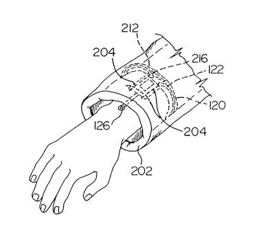
Figures 15 and 16 more particularly illustrate a use of
the invention and depict an arm of the wearer in association with
a protective suit in which the invention is installed. The
backing 26 (or 26') is sewn into the material 200 of cuff 202 by
stitching 204. The inner material 200 of cuff 202 has an
aperture 208 through which housing 32 (or 32') extends. Cuff 202
may also have reinforcing material (not shown) to which backing
26 (or 26') is sewn. Adjacent aperture 208 is a stitched,
peripheral passageway 210 defined by stitching 212, 214 about the
cuff and through which cord 120 is threaded. Cord end 122 is
secured to backing plate aperture 34 and free end 126 is passed
through the lock device as previously described. Appropriate
-- 11 --
201 l2nO
holes 216 are in the inner material of the passageway to permit
the cord to exit and connect with the backing plate. During
normal wear cuff 202 is loose enough that there is no difficulty
in placing fingers and thumb of a hand to grasp the end 126 or
pull ring 168 inside the cuff 202. End 126 could have a piece of
material such as Velcro ~ associated with it and in association
with like material sewn to the inside of the cuff, it could be
detachably secured to the cuff.
A preferred material for the backing and housing is
sewable plastic material such as nylon which will flex
sufficiently to permit assembly of the cam lock to the housing
and can be pierced by sewing needles. The cam lock may be of an
acetal plastic.
Although we have described particularly preferred
embodiments, it will be appreciated by those skilled in the art
that variations and modifications of the invention are possible
within the ambit of the claims herein.