Note: Descriptions are shown in the official language in which they were submitted.
- 201~ ?,91
Description -
POWER TRANSFERRING ARRANGEMENT ~
5 Technical Field -
This invention relates to an arrangement for
transferring electrical energy between a work vehicle
and a load transfer station and more particularly to a
power transferring arrangement having a contact
portion which is movable relative to the work vehicle
and engageable with a receptacle mounted on the load
transfer station in response to the work vehicle being
at a preselected position relative to the load
transfer station.
Back~round Art
Work vehicles such as lift trucks, automated
guided vehicles, mobile transporters and the like are ~ -
often utilized for transferring a load such as, a
20 pallet, a work piece, a tub and the like between load
transfer stations such as, storage areas, machining
cells, conveyors and assembly lines. These load
transfer stations have often have propelled devices
such as, motor driven conveyors, drills, mills,
25 grinders etc. which require a source of electric
energy. Thus, the facility is fixedly wired in an
` appropriate manner to transfer electrical current from
the house main to the electric drive motors. This
permanent wiring is satisfactory in applications where
30 the work being performed remains constant over a
relatively long period of time. However, in
6 applications where the load transfer stations are
?~ frequently moved due to changes in storage, machining
and assembly requirements, the fixed wiring is a
35 problem. Often the ability to move the wiring is
20~ 129~
--2--
extremely difficult due to the construction of the
facility and very costly in both time and money.
In applications where there are numerous
load transfer stations the cost and complexity
associated with providing electrical wiring for each
station is substantial. As a result of this excessive
cost the number of load transfer stations is reduced
from the optimum. As a result the efficiency of the
operation is less than achievable which ultimately
increases the cost of the product or service to the
- customer.
Each of the load transfer stations, in
addition to requiring electrical energy for powering
the motors, require communication sensors for the
purpose of turning on and off the motors when a load
is ready to be transferred from the work vehicle. It
; is emphasized that each load transfer station requires
communication sensors. As a result the cost and
complexity of each load transfer station is increased.
It has been known to drive a load transfer
, station conveyor by a vehicle mounted mechanical drive
' system of the friction or coupling type. One such a
; system is shown in European Patent No. 0100867, to Max
il, Braendli et al, which published on February 22, 1984.
This patent discloses an automatic guided vehicle
l having a roller deck and a conveyor stand having a
`'1 roller deck. A coupling half on the vehicle is
matable with a coupling half on the conveyor at an
aligned position of the coupling half. The coupling
half on the vehicle is connected to a roller deck
drive motor and transfers powered rotary motion from
~ the conveyor drive motor through the coupling half to
.~ the coupling half on the conveyor stand. The conveyor
stand coupling half is drivingly connected to the
conveyor stand rollers and rotates the rollers in
1. ~ .
` 20~L~29~L
response to rotation thereof. A mechanical drive
system such as this is not satisfactory in that the
amount of power being transferred and the speed of
operation is limited to the functional characteristics
of the vehicle conveyor drive motor. Thus, the
maximum size of the conveyor stand is limited in load
capacity, conveyor length and the like. As a result,
the number of applications are limited to just a few.
In addition to the size limitation of the
lo stand mounted conveyor, the two coupling halves must
be accurately aligned relative to each other in order
to permit successful mating and power transfer. Thus,
the surface upon which the vehicle operates must be of
the highest quality in order to maintain accuracy in
the distance from the surface to each of the coupling
i halves. In applications where a large number of
conveyor stands are used the cost of providing such
close tolerances is extremely difficult. The dynamics
i of the vehicle further adds to the alignment problems.
dl 20 Since the load being carried on the vehicle will vary
in magnitude the elevational distance between the
surface and the coupling will also vary. This is
~l based factors such as vehicle frame deflection, tire
crush and suspension sag.
~ 25 In the event that the automatic guided
'~, vehicle docks at a skewed or angled position relative
~ to the conveyor the ability to successfully achieve
'i~ coupling will be unlikely. This will result in
undesirable down time and delays until the problem is
corrected such as, by manual intervention by a vehicle
system operator.
In automatic guided vehicles in which
mechanical power transfer, such as disclosed in the
Max Braendli et al. publication, is provided, extreme
accuracy of docking is mandatory. In order to achieve
~, .
!, .. ,-' ~ ' : . , ~ , ,
21~112~1
this accuracy a sophisticated vehicle control system
is required. Such a system utilizes expensive and
elaborate sensors to identify when the vehicle is in
position to dock. Such systems often fail to be
accurate enough to precisely locate the vehicle
relative to the conveyor stand. Thus, premature wear
of the mechanical drive coupling or failure to mate
often occurs.
Mechanical drives such as shown in the Max
Braendli et al. publication do not transfer of
electrical energy for the powering of secondary
functions on the load transfer station. Therefore,
control of the conveyor, the load being transferred,
the stop gates on the load transfer station and the
like is not available. As a result the
controllability and flexibility of operation of the
load transfer station is limited and only mechanical
conveyor drive is provided.
, The present invention is directed to
', 20 overcoming one or more of the problems as set forth
, above.
i Disclosure of the Invention
, In one aspect of the present invention, -
a power transferring arrangement for passing
electrical energy from a source of electrical energy
and between an automatic guided vehicle having a
~' frame, and a longitudinal vehicle axis, and a load
transfer station having an electrically powered motor
;~ 30 is provided. A contactor assembly has a contacting
head portion which is connected to the source of -
`` electrical energy and movably connected to the frame.
~` The contacting head portion is movable between a first
position closely adjacent the frame and a second
position outwardly of the frame and spaced from the
~,...
. '~ -- ,
20~ 29~
first position. A device is provided for receiving
the contacting head portion and passing electrical
energy from the contacting head portion to said
electric motor. A sensor senses the position of the
vehicle relative to the load transfer station and
delivers a position control signal in response to the
automatic guided vehicle being adjacent the load
~' transfer station. A control device is provided for
receiving the position control signal and for
delivering an actuator control signal in response to
receiving the position control signal. An actuator
receives the actuator control signal and moves the
contacting head portion from the first position toward
. the second position and into engagement with the
receiving device.
In another aspect of the present invention a
power transferring arrangement is provided for passing
electrical energy from a work vehicle having a frame,
~i a longitudinal vehicle axis, and a source of
electrical energy to a load transfer station having an
electrically powered motor. A contactor assembly has
~, a contacting head portion connected to the source of
electrical energy and movably connected to the frame.
~' The contacting head portion is movable between a first
position closely adjacent the frame and a second
position spaced outwardly of the frame and spaced from
the first position. The contactor assembly has a
guide housing, a guide member connected to the
contacting head portion and slidably connected to the
guide housing, and movable relative to the guide
~,
-~, housing between an extended position and a retracted
~-1 position. A biasing means urges the guide member
~, toward the extended position and permits movement of
, the guide member toward the retracted position in
response to the the external force being applied to
!
' '
~` .
- 2 ~ 9 ~
the contacting head portion. A receiving device on
the load transfer station is provided for receiving
the contacting head portion and passing electrical
energy from the contacting head portion to the
electric motor. An actuator connected to the guide
housing receives the actuator control signal and moves
the contacting head portion from the first position
toward said second position and into engagement with
the receiving device.
The power transferring arrangement provides
the transfer of electrical energy from a work vehicle
to a load transfer station. Thus, the limitations of
load transfer station size and capacity are overcome.
Since electrical energy and not mechanical rotary
power is being transferred, other devices such as
machine tools, assembly line tools and the like may be
powered by the vehicle.
The power transferring arrangement utilizes
sensors to control docking of the vehicle but, because
of the construction of the contacting head portion and
the receiving device the need for accuracy of position
is substantially relaxed over typical mechanical drive
systems. In addition the movability of the contacting --~
head portion from the first position to the second
position subsequent to docking reduces the potential
of damage to the contacting head portion and
associated elements since at all other times the head
portion is at the first position adjacent the vehicle
frame.
Since the contacting head portion is movable
-` in response to an external force being applied ;~
` thereto, an range of docking error is accommodated.
Therefore the distance between the vehicle and the
load transfer station may deviate within tolerances
from the nominal without affecting the ability of the
~'',''.
, , ~
2 ~ ~
--7--
contacting head portion to successfully engage
receiving device.
Projection of a guide member past the
contacting head portion provides a keying function
with the tapered bore of a receiving device and
prevents the contacting head portion from making
inadvertent electrical contact with another surface.
The ability of the contacting head portion
to pivot solves the problem of the vehicle docking at
lo a slight angle or skew relative to the load transfer
station without affecting the ability to mate for
electrical energy transfer.
Brief Description of the Drawinqs
Fig. 1 is a diagrammatic top plan view of an
embodiment of the present invention showing an
automatic guided vehicle docked adjacent a load
transfer station with the contacting head portion of a
power transferring arrangement shown in phantom lines
engaging a receiving means;
Fig. 2 is a diagrammatic rear elevational
view taken along lines 2-2 of Fig.1;
Fig. 3 is a diagrammatic crossectional view
of the power transferring arrangement of Fig. l;
Fig. 4 is a diagrammatic crossectional view
taken along lines 4-4 of Fig. 3;
Fig. 5 is a diagrammatic crossectional view
taken along lines 5-5 of Fig. 3; and
Fig. 6 is a diagrammatic schematic
representation of the vehicle control system.
~, ,
Best Mode For Carryina Out the Invention
With reference to the drawings, and
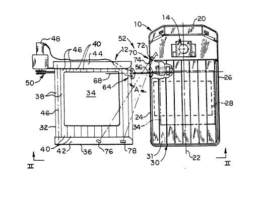
particularly Figs. 1 and 2, a work vehicle 10 of the
2~2~1
--8--
type used to transfer loads and the like between
various load transfer stations 12 is provided. The
particular work vehicle 10 shown is as an automatic
guided carrier vehicle however other material handling
vehicles utilized in manufacturing, storage and
warehousing applications are considered within the
scope of this invention. The automatic guided vehicle
(AG~) disclosed herein is driverless and able to
travel from location to location without human
lo intervention. It is free ranging and able to navigate
between locations without the need for wires,
reflective tape, or markings on the floor. The AGV
utilizes a laser scanner 14 mounted on the vehicle and
a plurality of spaced apart bar coded targets (not
shown) mounted within the facility for navigation
purposes. The laser scanner reads the location of the
targets and a navigation controller 16 (Fig. 6) on the ~
vehicle 10 calculates using triangulation the location~ ~-
of the vehicle and guides the vehicle along a
preprogrammed path stored in memory. The vehicle also
has the ability to dead-reckon, for example., to
travel along a preprogrammed path stored in the memory
of the vehicle controller without the aid of external
information. To achieve dead-reckoning the vehicle
travel is continuously monitored by on-board sensors
(not shown), such as, rotation, position and steering
angle resolvers (all not shown) associated with at
least one of the vehicle wheels 18. This information
is delivered to the controller 16 and the controller,
based on this feedback, controls the operation of the
vehicle 12. Thus, in the event the targets become
blocked the ability to dead-reckon allows the vehicle
to continue to travel when the laser/targets are
blocked for a preselected distance of vehicle travel.
' ~:
2~12~
g
The vehicle 10 has a frame 20 and a
longitudinal vehicle axis 22 which extends
substantially parallel to and between first and second
frame sides 24, 26. The scanner is mounted on an
upper end portion of the frame 20 and the wheels 18
are rotatively connected to the frame 20 in a
conventional manner. A source of electrical energy
28, such as a storage battery, and the like is
supported on the frame 20 at a location beneath a load
supporting device 30 mounted on the frame 20 and
between the first and second sides 24,26. The source
of electrical energy may also include other devices
which generate electrical energy in the form of
signals without departing from the scope of the
invention. The load supporting device 30 disclosed
herein is a powered roller deck 31 of conventional
design having a vehicle conveyor drive motor (not
shown). Other types of load supporting devices such
as, unpowered rollers, conveyor belts, tables, lift
masts, side loading forks and the like are considered
equivalents and within the spirit of the invention.
The load transfer station 12 disclosed
herein is a powered roller conveyor 32 capable of
transferring a load 34. However, other types of load
transferring stations 12 such as, unpowered roller
conveyors, belt and chain conveyors and the like are
considered equivalents and within the scope of this
invention. It is to be noted that the various load
transfer stations are utilized to deliver load to a
machine tool, storage area and assembly area. The
load transfer station 12 has a frame 36 to which a
plurality of rollers 3g are rotatively connected at
their end portions 40. The rollers 38 are arranged
parallel to each other and suitable for passing the
load 34 sequentially along the rollers 38. The
-` 20~291
--10--
station frame 36 has first and second spaced apart
substantially parallel guide rails 42,44 which extend
above an upper planar surface 46 defined by tangent
locations on the rollers 38 and maintains the load 34
on the rollers 38 and guides the load 34 during
movement across the planar surface 46 defined by the
rollers 38.
The load transfer station 12 has an electric
motor 48 for rotating the rollers 38 and propelling
the load 38 therealong. The electric motor 48 is
; mounted on the station frame 36 and drivingly
connected to the rollers 38 at one end portion 40 ~ -
thereof by a chain and sprocket arrangement 50 of
conventional design. The powered roller deck 31 of
the vehicle is constructed in a manner similar to that
of the load transfer station 12 powered roller
conveyor 32 and therefore will not be discussed in any
; greater detail. It is to be noted that other electric
, motors may be provided on the station 12 for driving
devices such as manufacturing tools, stop gates and
the like. Also, other devices, such as, electrically
powered sensors and control systems may be provided on -~
the load transfer station.
Referring to Figs, 1,2,3, and 6, a power
transferring arrangement 52 is provided for passing
electrical energy from the source of electrical energy
28 on the vehicle 10 to the electric motor 48
associated with the load transfer station 12. The
power transferring arrangement 52 includes a contactor
assembly 54 having a contacting head portion 56. As
shown in Fig. 6, the contacting head portion 56 is
connected to the source of electrical energy 28 and a
ground potential 58 by conductors 60,62, respectively.
It should be noted that additional conductors may be
provided without departing from the invention.
', ' .
- 201~ 2~
'; -11
.
- Referring back to Figs. 1 and 2, the contactor
assembly 54 is connected to the vehicle frame 20 and
the contacting head portion 56 is movable relative to
the vehicle frame 20 between a first position closely
adjacent the vehicle frame 20 and a second position
~ outwardly of the vehicle frame 20, spaced from the
;î''! first position. The contacting head portion 56 is
~ shown in solid lines at the first position and in-
tl phantom lines at the second position. Preferably, at
the first position, the contacting head portion 56 is
between the first and second frame sides 24,26 so that
.,
contact with external objects during vehicle travel is
avoided and damage to the contacting assembly 54 is
prevented.
A means 64 is provided for receiving the
contacting head portion 56 and for passing electric
energy from the contacting head portion 56 to the
electric motor 48 and control system (not shown)
associated with the load transfer station 12. It is
to be reiterated that the electric motor 48 may be
' used to power any one of or a combination of the
devices or sensors and the like, as discussed above,
without departing from the spirit of the invention.
The receiving means 64 is mounted on the station frame
36 at a preselected elevational location from vehicle
' supporting surface 66 so that the contacting head
portion 56 and the receiving means 64 may be aligned
` for engagement with each other. An axis 68 of the
contactor assembly 54, along which the contacting head
portion 56 moves, extends in a transverse direction
relative to the longitudinal vehicle axis 22 and is
preferably perpendicular to the first frame side 24.
The preselected normal distance from the axis 68 to
the underlying surface 66 is equal in magnitude to the
- 35 preselected normal distance from the receiving means ;
:~ -
~ ,:
20~1291
-12-
64 to the surface 66. Therefore, when the vehicle 10
is docked at a preselected location adjacent the load,
the contacting head portion 56 is aligned with the
receiving means 64 for engagement by the contacting
head portion 56 upon movement of the contacting head
portion 56 from its first position toward its second
position.
A means 70 is provided for sensing the
position of the automatic guided vehicle 10 relative
j 10 to the load transfer station 12 and for delivering a
position control signal in response to the automatic
guided vehicle 10 being at the above noted preselected
location adjacent the load transfer station 12. The
sensing means 70 preferable includes first and second
sensors 72,74 mounted on the vehicle frame 20 at
preselected locations on the frame 20 hereinafter
discussed. The first and second sensors 72,74 are
each adapted to deliver electromagnetic radiation and
receive a reflection of the electromagnetic radiation.
The means 70 also includes first and second reflective
members 76,78 mounted at preselected spaced apart
locations on the load transfer station 12 and
particularly on the frame 36. The first and second
sensors 76,78 are shown as being mounted on the first
guide rail 42; however, other locations on the frame
36 would be suitable substitutes. The first and
second reflective members 76,78 are aligned to reflect
electromagnetic radiation to the first and second
sensors 72,74, respectively, in response to the
vehicle 10 being at the predetermined docked location
relative to the load transfer station 12 mentioned
above. The first and second sensors 72,74 are each
mounted on the vehicle frame 20 at a location near the
, frame first side 24 and at a normal elevational
` 35 distance from the surface 66 equal in magnitude to the
201 ~ 291
-13-
. normal elevational distance from the surface 66 to
each of the reflective members 76,78. The first and
second sensors 72,74 are preferably positioned to
deliver electromagnetic radiation at a preselected
included angle "A" relative to each other and in a
direction transverse the vehicle longitudinal axis 22.
Angle "A" lies in a plane 8' which is defined by the
elevational height of the sensors 72,74 and reflective
members 76,78 at the preselected location of the
vehicle 10. The angularity of the sensors 72,74 and
the spacing of the reflective members 76,78
establishes the location at which the vehicle 10 is
docked for successful engagement between the
contacting head portion 56 and the receiving means 64.
The first sensor 72 also serves to identify if a load
34 is present on the powered roller conveyor 32 when
the load 34 prevents electromagnetic radiation
delivered by the first sensor 72 from being reflected
by the first reflective member 76 back to the first
sensor 72 while the second sensor 74 and second
reflective member is aligned and receiving reflected
electromagnetic radiation. Thus, alignment of a the
second sensor 74 and second reflective member 78 is
adequate to properly locate the vehicle 10 for
alignment purposes. It is to be mentioned that some
deviation from the nominal aligned vehicle position is
permitted without affecting engagement for power
transferring purposes. The first and second sensors
72,74 each deliver a position control signal in
response to receiving a reflection of their respective
delivered electromagnetic radiation. The control ~-
signal delivered is preferably a change in state of
the sensor, such as + to - or vice versa. ~-
Referring to Fig. 3, the receiving means 64 ~-~
has a supporting portion 80' which is constructed of an
`, '~;
.. ~ ~ -.
-::
,
..
. $. : ::: :: - . . . -:: : - - . . : : -
20~291
-14-
electrically nonconductive material. The supporting
portion 80' is secured to the station frame 36 in any
suitable manner such as by fasteners 81. First and
second spaced apart receiving pads 82,84 are connected
to the supporting portion 80' in any suitable manner.
It should be noted that additional receiving pads may
be provided without departing from the invention.
First and second conductors 86,88 are connected to the
first and second receiving pads 82,84 and to the
electrical motor 48 and pass electrical current from
the contacting head portion 56 to the load transfer
station's electrically powered motor 48.
The contacting head portion 56 has first and
second contact tips 90,92 and a beam member 94. The
beam member has first and second spaced apart end
portions 96,98 and an intermediate portion 100 located
between the first and second end portions 96,98. The
first and second contact tips 90,92 are connected to
the first and second end portions 96,98 and connected
by the conductors 60,62, to the source 28 and ground
potential 58, respectively. Each of the contact tips
90,92 have an electrical insulator 102 which is
disposed in an aperture 104 in the first and second
end portions 96,98 and insulates ~ach of the contact
tips 90,92 disposed in the apertures from contact with
the beam member 94. The contact tips 90,92 preferably
have spherical faces to assure contact when at an
angle relative to the receiving means 64. The spacing
of the first and second contact tips 90,92 and the
first and second receiving pads 82,84, are
substantially equal so that the first contact tip 90 -~
, is movable into engagement with the first receiving
pad 82 and the second contact tip 92 is movable into
~, engagement with the second receiving pad 84, both in --~
response to movement of the contact head portion 56
., '~,;
. . . .. , .. . . . . - . :::
20~291
-15-
toward the second position. Therefore, the first
receiving pad 82 is connectable to the electrical
source 28 and the second receiving pad 84 is
connectable to the ground potential 58 upon engagement
5 between receiving means 64 and the contacting head
portion 56. The electric motor 48 is then powered by
the source of electrical energy 28 of vehicle lo. It
is to be noted that one could utilize the power
transferring arrangement 52 to transfer power from a
lo charging station (not shown) to the vehicle 10 for
charging the battery 28 without departing from the
nventlon .
As best seen in Fig. 6, a control means 106
is provided for receiving the position control signal
15 and delivering an actuator control signal in response
to receiving the position control signal. Delivery of
the actuator control signal, as shown, allows
electrical power to be delivered to the actuator means
108. The position control signal, as discussed above,
, 20 requires at least a signal from the second sensor 74.
An actuator means 108 receives the actuator control
signal and moving the contacting head portion 56 from
t the first position toward the second position and into
engagement with the receiving means 64. The first and
~' 25 second sensors 72,74 are each adapted to deliver a
position control signal in response to receiving a
reflection of their delivered electromagnetic
radiation. When the control means 106 receives
; position control signals from both the first and
30 second sensors 72,74 it processes this information and
delivers a braking control signal in response thereto.
~' Should the control means 106 receive a position
control signal from the second sensor 74 and not the
s~ first sensor 72, both a braking and vehicle conveyor
35 drive signal will be delivered in response to
! ~ ~
''' ~: :~:
` i~ii :: :
291~ 291
-16-
receiving only the position control signal of the
second sensor 74.
Referring to Fig. 3, the actuator means 108
for moving the contacting head portion 56 from the
first position toward the second position and into
engagement with the receiving means 64 is preferably
an electrically driven linear motor 114 having a
housing 110, a rod 112 slidably disposed in the
housing 110 and an electric motor 114 operatively
connected to the rod 112 and adapted to move the rod
112 linearly relative to the housing 110. Linear
actuators such as this are well known in the art.
Therefore, the construction will not be discussed in
any greater detail. As best seen in Fig. 6, the
` 15 electric motor 114 is connected to the control means
106 by conductor 116 and receives the actuator control
signal through conductor 116. The control means 106
is also connected to ground potential 58.
; Means 118 is provided for receiving the
; 20 brake control signal delivered by the control means
106 and stopping movement of the vehicle 10 in
response to receiving the brake control signal. The
`~. stopping means 118 preferably includes first and
second spring applied electrically released brakes
'~ 25 120,122 of a conventional design. The first and
'~ second brakes 120,122 are each connected to a wheel 18
' and a respective first and second vehicle drive motor
; 124,126 such as by shafts 128. The brake control ~ -
signal is preferably a change in state signal
30 delivered from the control means 106 to the brakes ~ ;
120,122. Thus, in the absence of a positive
electrical (+) signal the brakes are spring applied.
The brake control signals are delivered to the first
and second brakes 120,122 by conductors 130,132.
'~ 35 ~;~
:,. ' .
:~ , :
`` 201~91
Llke the first and second brakes 120,122,
the first and second vehicle drive motors 124, 126 are
connected to the control means 106 by conductors
134,136 which deliver a motor control signal from the
control means 106 to the first and second vehicle
drive motors 124,126. The motor control signal, which
is preferably a change of state signal, is delivered
to the first and second drive motors and disables the
first and second vehicle drive motors from rotating
the wheels 18 whenever the second sensor 74 is
receiving a reflection of its delivered
electromagnetic radiation and the vehicle 10 is
aligned.
The control means 106 preferable includes a
micro computer which is capable of controlling the
operation of the automatic guided vehicle 10 in
response to feedback of a plurality of sensing devices
(all not shown) on the vehicle 10 and in response to
preprogrammed instructions located in memory. The
control means 106 is connected to the first and second
sensors 72,74 by first and second conductors 138,140
which deliver the position control signals from each ~-
of the sensors 72,74 to the control means 106. Also
the navigation controller 16 and the vehicle the
conveyor drive motor 33 are connected to the control
means by conductors 142,144, respectively which
deliver control signals therebetween. The control
means 106, controls operation of the drive motors
124,126, based on signals from the navigation
controller 16, the first and second sensors 72,74 and
the aforementioned other sensors. The vehicle
conveyor drive motor 33 responds to signals delivered
from the control means 106 by conduit 144 which turns
the conveyor motor 33 on or off for example, in
response to the control means 106 receiving a signal
20~12~
-18-
from the second sensor 74 which based on the
preprogrammed instructions informs the control means
106 that the vehicle is properly docked at the load
transfer station 12 and ready to receive or eject a
load 34.
The contactor assembly 54 includes a motion
means 142 which permits movement of the contacting
head portion 56 relative to the actuator means 108 in
response to an external force of a preselected value
being applied to the contacting head portion 56. The
contacting head portion 56 is preferably movable in
directions transverse the vehicle axis 22 and along
the axis 68 of the contactor assembly 54 which is
preferably linear and oriented substantially normal to
the axis 22 in response to the external force of the
preselected value being applied to the contacting head
and along the axis 68. The force must be of a ~-
magnitude satisfactory for maintain the contacting
head portion 56 in engagement with the receiving means
64, from bouncing and inadvertent movement relative
thereto so that arcing and the like may be prevented
during loading and unloading of the vehicle 10. The ~-
motion means 142 also accommodates for a limited :~
amount of error in vehicle positioning, such as the
distance between the vehicle and the load transfer
station 12, by allowing biased movement of the
~ contacting head portion 56 relative to the load
:~ transfer station 12. ~ ~
The contactor assembly S4 and particularly :
the motion means 142 thereof includes means 144 for
guiding the contacting head portion 56 for movement
along linear axis 68 and transverse the longitudinal
vehicle axis 22 during movement of the contacting head
portion 56 between the first and second spaced apart
positions. The guiding means 144 includes a housing
., :
,~
2011291
--19--
146 connected to the actuator means 108 and a guide
member 148 connected to the contacting head portion
56. The housing 146 is slidably connected to the
vehicle frame 20 by a bracket assembly 150 having a
body 152 and a connecting flange 154. The body 152
and connecting flange 154 are secured to each other
and the vehicle frame 20 in any suitable manner, for
example, by threaded fastener 156. The body 152 has
first and second substantially axially parallel
lo apertures 158,160 disposed therethrough for receiving
guide housing 146 and actuator housing 110. The guide
housing 146 is cylindrical in shape and has an axial
bore 162 disposed longitudinally therethrough. The ~:
bore 162 has a step bore portion at a first end
portion 166 thereof which acts as a stop 164 for the
guide member 148. Alternately, the stop function may
be provided between the guide housing 146 and the
guide member 148 at the second end portion 176 of the ~-
guide housing without departing from the invention. ~
20 The guide member 148 is slidably disposed in the bore :
162 of the guide housing 146 and telescopically
movable along the axis 68 of the bore 162 between
i extended and retracted positions relative to the guide ~ :
housing 146. The guide member 148 is an elongated
25 cylindrically shaped spool having first and second~:;
i spaced apart portions 167,169 which are slidably :
disposed in engagement with the bore 162. First and
second bushings 168,170 are disposed in the first
aperture 158 of the body 152 at opposite ends of the
body 152. The flanged bushings 168,170 engage the
guide housing 146 and guide the housing 146 for linear
movement along the axis 68 in response to linear
movement of the actuator rod 112.
The actuator housing 110, which is
cylindrically shaped, is disposed in the second
.
: :
2~1~2~1
-20-
aperture 160 of the body 152 and securely retained
therein from axial, radial and rotary movement in any
suitable manner, for example, a set screw 172. The
actuator housing 110, guide housing 146 and guide
member 148, as a result of the substantial parallel
orientation of the apertures 158,162 and the fit-up
with associated components, such as the bushings
168,170, bore 162 and guide member 148, are maintained
substantially axially parallel to each other. As best
lO seen in Figs. 4 and 5, the rod 112 is connected to the ~:
guide housing 146 by a flange assembly 174. The
flange assembly 174 is clamping secured to the guide .
housing 146 at a second end portion 176 thereof and ~
pivotally connected between bifrucated portions 178 :
thereof to rod 112 by a pin 180. The guide housing ~:
second end portion 176 is disposed in a bore 182 in
the flange assembly 174. The flange assembly 174 is
clamped to the guide housing 146 by virtue of threaded ~:
fastener 184 and split portion 186.
The motion means 142 also includes a biasing
means 188 for urging the guide member 148 toward the ~ ::
extended position, at which the guide member is ~:
engaged with the stop 164, and the retracted position ~
axially spaced from the stop 164 in response to the . :
external force being applied to the contacting head
` portion 56. The biasing means 188 includes a coil
spring 190 which is disposed in the bore 162 at the -
first end portion 166 of the guide housing 146 and
between the guide member 148 and an end cap 192 :
located at the first end portion 169 of the guide
housing 146. The spring 190 bears against the first
end portion 167 of guide member 148 and urges the
guide member 148 toward the extended position. This
spring maintains the aforementioned force (preload) of
the contacting head portion 56 against the receiving
~ '
.~. . - . . .
2~ 12gl
-21-
means 64 during electrical energy transfer. r~he end
cap 192 disclosed herein has a bore 194 disposed
therethrough and loosely slidably positioned about the
actuator housing 110. This serves to prevent rotation
of the guide housing 146 in the bushings 168,170.
Other techniques for preventing rotation of the guide
- housing 146 may be utilized, such as guide rods,
-` anti-rotation tabs and stops. It should be noted that
the end cap 192 may be integral with the guide housing
146 instead of being screwthreadably connected thereto
and retained from rotation by set screw 172.
The motion means 142 also includes a stop
196 which is connected to one of the guide housing 146
and guide member 148 and engageable with the other of
the guide housing 146 and guide member 148. The stop
196 is preferably a pin 198 which is disposed in a
radial through cross bore 200 disposed in the guide -
!., housing 146 at the second end portion 176 thereof and
~! in an axially oriented elongated slot 202 disposed
`, 20 radially through the second end portion 169 of the
guide member 148. The pin 198 by virtue of its
connection to the guide housing 146 and disposition in
~' the slot 202 and engagement with the guide member 148
, and particularly the sides of the elongated slot 202 -~
prevents rotation of the guide member 148 relative to
the guide housing 146. As a result the contacting
head portion 56 is maintained from rotation about axis
-` 68 and for subsequent engagement with the receiving
means 64. The slot 202 also may serve as an axial
stop for the guide member 148 during movement of the
guide member along the axis 68 and establish the
extended and/or retracted positions of the guide
member 148 in situations where the stop 164 is
i' omitted.
;" :.
. .
i
201~291
-22-
The contacting head portion 56 preferably
includes a beam member 204 having the first and second
end portions 96,98, and intermediate portion 100. The ~-
: beam member 204 has an aperture 206 disposed in the
: 5 intermediate portion 100 and apertures 104 in the
first and second end portions 96,98. Aperture 106
- preferably has a convex crossection, as shown in
, Fig.3, to increase the amount of pivotal movement of ~
the beam member 204. As previously discussed the ~ ;
10 contact tips 90,92 are disposed in the apertures 104
and connected to the first and second end portions
- 96,98, respectively.
Means 203 is provided for pivotally ~ :
connecting the contacting head portion 56 to the guide
15 member 148 and maintaining the contacting head portion ~-
' 56 to the guide member 148 and maintaining the ~ .
' contacting head portion 56 for pivotal movement about
the pivotal connecting means 203 in response to a
i tipping force being applied to the contacting head : .
-~ 20 portion 56. The second end portion 169 of the guide
member 148 is pivotally connected to the beam member
204 via a pivot pin 208 which allows for pivotal
movement of the beam member 204 about the pin 208.
Thus full and complete contact between the first and
second contact tips 90,92 and the first and second
receiving pads 82,84, respectively, is allowed in
response to forceable engagement therewith. Pivotal
~-, movement of the beam member 204 occurs when the
vehicle is skewed, cocked or otherwise not squarely
. 30 oriented relative to the load transfer station 12 and ~ -
,, ,
,, forceable engagement is made beam member 204 and the
! receiving means 64.
The second end portion 169 of the guide
~. member 148 has a tapered portion 210 which guides the
'.`'J 35 contacting head portion 56 relative to the receiving
,
:.
,:~ w~ ~ - , , - . : -:
20~ ~ ~91
means 64 just prior to contact between the receiving
means 64 and the contacting head portion 56 and
prevents engagement of the contacting head portion 56
with other undesirable and unappropriate surfaces.
The tapered end portion 210 extends past the
contacting head portion 56 an amount sufficient for
preventing contact between the contacting head portion
56 and another surface when the contacting head
portion 56 is pivoted the maximum allowable amount
about the pivot pin 208. The tapered portion 210 is
disposable in a tapered aperture ~12, which is
preferably an elongated slot, disposed in the
supporting portion 80 of the receiving means 64 when
the contacting head portion 56 is at the second
15 position. The tapered bore 212 is effective to permit ~-
contact of the contacting head portion 56 with the
receiving means 64 when properly aligned and guidably
-urges the contacting head portion 56 transversely
relative to to the axis 68 upon engagement between the
tapered bore 212 and tapered end portion 210 during ~ -
movement of the contacting head portion 56 toward the
second position.
A means 214 is provided for stopping
movement of the actuator means 108 in response to said
guide member 148 being at said retracted position.
The retracted position is a predetermined position
between the spring 190 going solid and the extended
position of the guide member 148. Factors such as the
amount of acceptable error in vehicle 10 spacing from
the load transfer station 12 are used to determine the
amount of movement between the extended and retracted
positions. The stopping means 214 includes an
; electrical switch 216 connected to the guide housing
146 and actuatable in response to the guide member -
being at the retracted position. The switch 216
~.`3 :~
.' :
.', ~
:
~011291
~ -24-
.~ "
prevents electrical energy from being delivered to the
actuator means 108 in response to the guide member 148
being at the retracted position. The switch 216 shown
is screw threadably mounted on the end cap 192 and has
a plunger 218 engageable with the guide member 148.
The plunger moves the switch 216 between open and
closed positions. It is to be emphasized that other
types of switches such as optical, proximity,
Hall-Effect and the like would be suitable substitutes
for the aforementioned described mechanical switch 216
without departing from the spirit of the invention.
A proximity sensor 220, of any suitable
- type, is connected to flange 154 adjacent the
contacting head portion 56, at the first position of
the contacting head portion 56, is connected to the
- control means 106, and delivers a control signal at
the first position of the contacting head portion 56.
The control signal delivered by the proximity sensor
220 is a change in state signal based on the absence
;~ 20 and presence of the contacting head portion 56.
.
Industrial APplicability
` With reference to the drawings, as the
~ automatic guided vehicle 10 approaches the load
- 25 transfer station 12, at which the vehicle is to dock,
the vehicle 10 slows, based on preprogrammed
instructions stored in the control means 106. When --
the vehicle reaches the aligned position, i.e., where
- the contacting head portion 56 is aligned for
engagement with the receiving means 64 upon movement
of the contacting head along the axis 68 toward the
~ second position, the sensing means 70 delivers the
`,!, control signal to the control means. The control
means 106 responds to this received control signal and
~`~ 35 and delivers a signal to stop power to the drive
!,j~
, ~ .
,:.;
x~
201~
motors 124, 126 and release the spring applied brakes
120,122 to stop rotation of the wheels 18. The
vehicle 1o is now stopped and aligned for power
transfer.
As discussed above, the first and second
sensors 72,74, each deliver a control signal when a
reflection of the emitted electromagnetic is received,
respectively. Alignment is also achieved when only
one sensor is receiving reflected electromagnetic
radiation. The absence of received reflected
electromagnetic radiation by the first sensor 72 and -
the presence of received electromagnetic radiation by
the second sensor 74 indicates that a load 34 is
present at the load transfer station 12 and ready to
be deposited on the vehicle 10. Thus, a signal
received only from the second sensor 74, by the
control means 106, will indicate a load present on
the load transfer station 12. The control means 106
will compare this information to the preprogrammed
instructions in memory and if appropriate will be
ready to make power transfer connection and receive
the load 34.
Upon completion of alignment the control
means 106 will actuate the actuator means 108 which
will move the contacting head portion 56 from the
` first position between the vehicle sides 24,26 toward
a second position outside the vehicle sides 24,26 and
into contact with the receiving means 64. Should the
` vehicle 10 be skewed or otherwise not square with the
load transfer station 12 the pivotal connecting means
203 allows for pivotal movement of the contacting head
portion 56 relative to the receiving means in response
; to contact therewith and full engagement between the
first and second contact tips and the first and second
receiving pads, respectively.
'.:
.i .~
:~`. ! .
20112~
-26-
As the actuator means 108 moves the
contacting head portion 56 into engagement with the
receiving means 64 the biasing means 188 limits the
force of engagement between the contacting head
portion 56 and the receiving means 64 to a preselected
maximum amount so that excessive loading is prevented
while adequate contacting loading is maintained. The
biasing means 188 also allows for movement of the
guide housing 146 relative to the guide member 148 so
that tolerances associated with the distance between
the vehicle 10 and the load support station 12 can be
accommodated during movement toward the second
position.
When the actuator means 108 is extended the
stopping means 214 is actuated which ceases further
extension of the actuator means 108 and movement of
the contactor assembly 54 toward the second position.
The switch 216 when actuated by contact between
plunger 218 and guide member 148 signals the control
means 106 to cease further extension of the actuator
~! means 108.
Should improper alignment take place the
tapered end portion 210 of the guide member 148 will
prevent engagement of the contacting head portion 56
with another improper surface since the tapered end
'~ portion contacts the improper surface first and
' prevents further movement of the contacting head
, portion 56. Therefore, the contacting head portion 56
`~, is only engageable with the receiving means 64 and
1 30 only when properly aligned for engagement.
Electrical energy is now deliverable from
the source of electrical energy 28 to the load
supporting station 12 and to the electric motor 48 of
the load transfer station 12. Thus, need for
permanent hard wiring of the load transfer station 12
;`,
,
2011291
. .
-27-
is eliminated and the flexibility of relocating the
load transfer station 12 is enhanced. Also,
electrical control signals may be delivered in the
same manner, between the vehicle 10 and load transfer
station 12, from other sources of electrical energy,
such as, control means 106, without departing from the
invention.
: The load 34 is then transferred from the
; load transfer station 12 to the vehicle 10 by the
powered roller conveyor 32 driven by motor 48. Once
the load is on the vehicle 10 the power transferring
arrangement 52 is actuated by the control means 106 to
retract from the second position toward the first
position and within the vehicle sides 24,26. When the
contacting head portion 56 is at the first position,
the control means 106 is signaled by the proximity
sensor 220 which results in the release of brakes
120,122 and the delivery of power to drive motors
126,126. The vehicle 10 is then free to transport the
load 34 to another load transfer station (not shown)
I for deposit purposes.
; Other aspects, objects and advantages of the
present invention can be obtained from a study of the
~, drawings, the disclosure and the appended claims~
`', 25 ~
-.
:i .:
,~