Language selection

Search

Patent 2011328 Summary

Third-party information liability

Some of the information on this Web page has been provided by external sources. The Government of Canada is not responsible for the accuracy, reliability or currency of the information supplied by external sources. Users wishing to rely upon this information should consult directly with the source of the information. Content provided by external sources is not subject to official languages, privacy and accessibility requirements.

Claims and Abstract availability

Any discrepancies in the text and image of the Claims and Abstract are due to differing posting times. Text of the Claims and Abstract are posted:

  • At the time the application is open to public inspection;
  • At the time of issue of the patent (grant).
(12) Patent: (11) CA 2011328
(54) English Title: SUPPORT DOWNTILT BRACKET FOR MOUNTING AN ANTENNA ON A METALLIC TOWER
(54) French Title: SUPPORT INCLINE VERS LE BAS POUR MONTAGE D'UNE ANTENNE SUR UNE TOUR METALLIQUE
Status: Expired and beyond the Period of Reversal
Bibliographic Data
(51) International Patent Classification (IPC):
  • H01Q 01/12 (2006.01)
  • F16M 11/06 (2006.01)
(72) Inventors :
  • BERNIER, MARC (Canada)
  • ROY, GILLES (Canada)
(73) Owners :
  • ROY TELECOMMUNICATIONS LTEE
(71) Applicants :
  • ROY TELECOMMUNICATIONS LTEE (Canada)
(74) Agent:
(74) Associate agent:
(45) Issued: 1995-08-22
(22) Filed Date: 1990-03-02
(41) Open to Public Inspection: 1990-11-01
Examination requested: 1990-08-23
Availability of licence: N/A
Dedicated to the Public: N/A
(25) Language of filing: English

Patent Cooperation Treaty (PCT): No

(30) Application Priority Data: None

Abstracts

English Abstract


A mechanical bracket for mounting a
telecommunication antenna on a metallic tower
comprises a pipe section to secure the bracket to the
tower. The angular position of the pipe section about
its longitudinal axis is selected to appropriately
orient the bracket. A transversal pivot bridges a
pair of spaced apart parallel plates of the bracket.
The antenna comprises a pole member with a free end
pivotally mounted on the pivot between the two plates.
A bolt and nut assembly traverses the pole member and
two arcuate slots respectively made in the parallel
plates. In operation, the pole member is rotated
about the pivot with the bolt sliding in the two
arcuate slots, and the bolt and nut assembly is
tightened when a desired position for the pole member,
and therefore for the antenna, is reached to thereby
lock the pole member and the antenna in this position.


Claims

Note: Claims are shown in the official language in which they were submitted.

The embodiments of the invention in which
an exclusive property or privilege is claimed are
defined as follows:
1. A mechanical bracket for mounting a
telecommunication antenna on an antenna support
structure while enabling spatial positioning of the
said antenna, comprising:
means for fixedly securing the mechanical
bracket to the antenna support structure; and
means for fastening the said antenna to
the mechanical bracket, said antenna fastening means
comprising (a) a pivot about which said antenna is
rotatable, and (b) means for locking in position the
said rotatable antenna; wherein:
the said bracket comprises a pair of
spaced apart parallel plates each comprising an
arcuate slot therein, and a pair of spaced apart plate
means for rigidly interconnecting said parallel
plates;
the said pivot is mounted between the two
parallel plates, it is perpendicular to the said
parallel plates, and is spaced apart from the arcuate
slots;
the said antenna comprises a pole member
with a free end pivotally mounted on said pivot
between the two parallel plates and between the two
plate means; and
the said locking means includes the two
arcuate slots in the parallel plates and a bolt and
nut assembly traversing the said slots and pole
member;
whereby, in operation, the pole member can
be pivoted about the said pivot with the bolt of the
said bolt and nut assembly sliding in the two arcuate
slots, and the said bolt and nut assembly can be

tightened when a desired position for the pole member,
and therefore for the said antenna, is reached to
thereby lock the pole member and the antenna in said
desired position.
2. The mechanical bracket of claim 1,
wherein the said bracket securing means comprises an
elongated member with a longitudinal axis, the said
elongated member having an angular position about is
longitudinal axis that can be selected to
appropriately orient the said bracket.
3. The mechanical bracket of claim 1, in
which the said elongated member is tubular and
cylindrical.

Description

Note: Descriptions are shown in the official language in which they were submitted.


^' 2011328
SUPPORT DOWNTILT BRACKET FOR MOUNTING AN
ANTENNA ON A METALLIC TOWER
BACKGROUND OF THE INVENTION
1. Field of the invention:
The present invention relates to a
mechanical bracket of simple design for mounting on
the top of a metallic tower an antenna for, in
particular but not exclusively, cellular telephony.
2. Brief description of the prior art:
A conventional device used to mount an
antenna for cellular telephony on the end of a
metallic tower comprises a plurality of articulated
arms. The mechanical articulations between the arms
enable correct orientation of the antenna but make the
resulting device complex and accordingly expensive.
Another drawback of such a conventional device is that
it is heavy. The charge on the tower due to each
antenna is therefore increased whereby fewer antennae
can be mounted on the top of the tower.
~;3L

20 1 1 328
OBJECT OF THE INVENTION
An object of the present invention is
therefore to elimitate the above discussed drawbacks
of the prior art by providing a light-weight
mechanical bracket of simple design capable of fixing
a telecommunication antenna to a tower while enabling
positional adjustment thereof.
SUMMARY OF THE INVENTION
More particularly, the subject invention is
concerned with a mechanical bracket for mounting a
telecommunication antenna on an antenna support
structure while enabling spatial positioning of that
antenna, comprising means for fixedly securing the
mechanical bracket to the antenna support structure;
and means for fastening the antenna to the mechanical
bracket, these antenna fastening means comprising (a)
a pivot about which the antenna is rotatable, and (b)
means for locking in position the rotatable antenna.
The bracket comprises a pair of spaced apart parallel
plates each comprising an arcuate slot therein, and a
pair of spaced apart plate means for rigidly
interconnecting the parallel plates. The pivot is
mounted between and perpendicular to the two parallel
plates, and is spaced apart from the arcuate slots.
The antenna comprises a pole member with a free end
pivotally mounted on the pivot between the two
parallel plates and between the two plate means, and
the locking means includes the two arcuate slots in
the parallel plates and a bolt and nut assembly
traversing these slots and pole member.

20 ~ 1 328
In operation, the pole member can be pivoted
about the pivot with the bolt of the bolt and nut
assembly sliding in the two arcuate slots, and this
bolt and nut assembly can be tightened when a desired
position for the pole member, and therefore for the
antenna, is reached to thereby lock the pole member
and the antenna in that desired position.
In accordance with an advantageous feature
of the invention, the bracket securing means comprises
an elongated, cylindrical tubular member with a
longitudinal axis, which tubular member having an
angular position about its longitudinal axis selected
to appropriately orient the bracket.
The objects, advantages and other features of
the present invention will become more apparent upon
reading of the following non restrictive description
of a preferred embodiment thereof, given by way of
example only with reference to the accompanying
drawings.

2{)11328
BRIEF DESCRIPTION OF THE DRAWINGS
In the appended drawings:
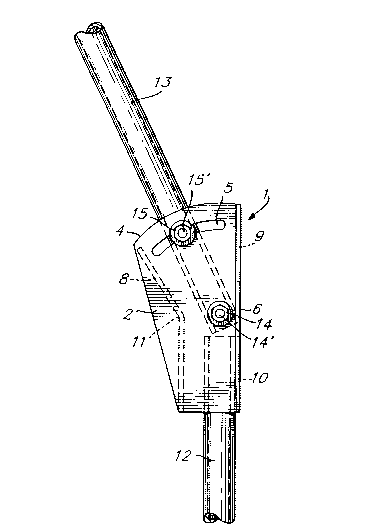
Figure 1 is a side, elevation view of a
bracket in accordance with the present invention;
Figure 2 is a top view of the bracket of
Figure l; and
Figure 3 is an enlarged, partial side
elevation view of the bracket of Figure 1 to which is
mounted the pole of a telecommunication antenna.
DETAILED DESCRIPTION OF THE PREFERRED EMBODIMENTS
As illustrated in Figures 1 and 2 of the
appended drawings, the preferred embodiment of the
bracket 1 of the invention comprises a pair of lateral
steel plates 2 and 3 which are symmetrical with
respect to a central plane parallel to these plates.
The shape of the plates 2 and 3 is shown in Figure 1.
In particular, each plate 2 and 3 has a semicircular
and inclined upper edge 4, as well as a semicircular
upper slot 5 parallel to the edge 4. The arcs of
circle defined by the edge 4 and slot 5 have a common
center on which is centered a hole 20. The vertical
rear edges 6 and 7 of the plates 2 and 3 are beveled.

,_ 2oll328
The lateral plates 2 and 3 are
interconnected through a set of three steel plates,
namely a front plate 8 and two rear plates 9 and 10,
welded to the lateral plates 2 and 3. As shown in
Figure 1, the front plate 8 defines an obtuse angle 11
and has a lower portion which is vertical. The rear
plates 9 and 10 are planar and rectangular, they
interconnect the beveled edges 6 and 7, are lying in
the same vertical plane one above the other, and are
spaced apart from each other by a given distance.
The bracket further comprises a vertical
pipe section 12 of which the upper end is inserted
between the lateral plates 2 and 3 and is welded to
the inner surfaces of these two plates. As
illustrated in Figure 2, the outer, cylindrical
surface of the pipe section 12 contacts the inner
surfaces of the plates 2, 3 and 10. The top edges of
the pipe section 12 and of the rear plate 10 are at
the same level, and the longitudinal axis of the
latter pipe section is parallel to the beveled edges
6 and 7.
Referring now to Figure 3 of the appended
drawings, the antenna comprises a pole 13 of which the
lower end is pivotally mounted to the bracket 1. The
pole 13 is typically a cylindrical tube made of
aluminum. More specifically, the lower end of the
pole 13 is introduced between the lateral plates 2 and
3, and a transversal bolt and nut assembly 14
traverses holes in the pole and the holes 20 in the

._, 2ol~3z8
latter plates. The pole 13 can therefore be rotated
about the pivot formed by the bolt 14' of assembly 14,
the spacing between the plates 9 and 10 providing
clearance for that purpose. The bolt and nut assembly
14 is therefore positioned on the center of the arcs
of circle defined by the edges 4 and the slots 5 of
the plates 2 and 3.
Another transversal bolt and nut assembly
1015 traverses holes in the pole 13 and the slots 5 in
the two plates 2 and 3. Accordingly, the bolt 15' of
assembly 15 slides into the slots 5 when the pole 13
is pivoted about the bolt 14'. In order to adjust the
position of the antenna, one has only to pivot the
pole 13 about the bolt 14', and as the antenna reaches
the desired position the bolt and nut assembly 15 is
tightened to lock the pole 13 and therefore the
antenna in this position.
20The bracket 1 can be installed on the end
of a metallic tower (not shown). For that purpose,
the pipe section 12 is fixed to the tower through
suitable fasteners (not shown). It is positioned
vertical using a level with its angular position about
its longitudinal axis selected to appropriately orient
the bracket 1. The last step in adju~ting the
position of the antenna is to rotate the pole 13 about
the bolt 14' and then to tighten the bolt and nut
assembly 15, as explained in the foregoing
description. The bolt and nut assembly 14 can then

` -
2(~328
also be tightened to increase the rigidity of the
fixation.
Of course, the pipe section 12 can be
fixed vertical on the tower with the plates 2, 3, 9
and 10 at the lower or the upper end thereof.
The bracket 1 in accordance with the
invention can be used to install on the top of a
metallic tower any type of telecommunication antenna,
in particular but not exclusively an antenna for
cellular telephony.
Although the present invention has been
described hereinabove with reference to a preferred
embodiment thereof, such an embodiment can be modified
at will, within the scope of the appended claims,
without departing from the spirit and nature of the
invention. In particular, the pipe section 12 can be
replaced by any other type of fastener suitable to
mount the bracket 1 on the metallic tower.

Representative Drawing
A single figure which represents the drawing illustrating the invention.
Administrative Status

2024-08-01:As part of the Next Generation Patents (NGP) transition, the Canadian Patents Database (CPD) now contains a more detailed Event History, which replicates the Event Log of our new back-office solution.

Please note that "Inactive:" events refers to events no longer in use in our new back-office solution.

For a clearer understanding of the status of the application/patent presented on this page, the site Disclaimer , as well as the definitions for Patent , Event History , Maintenance Fee  and Payment History  should be consulted.

Event History

Description Date
Inactive: IPC from MCD 2006-03-11
Time Limit for Reversal Expired 2002-03-04
Inactive: Adhoc Request Documented 2002-01-15
Inactive: Adhoc Request Documented 2001-09-28
Letter Sent 2001-03-02
Inactive: Entity size changed 1999-02-25
Inactive: Office letter 1998-09-09
Inactive: Inventor deleted 1998-09-09
Inactive: Office letter 1998-09-09
Inactive: Late MF processed 1998-08-14
Letter Sent 1998-03-02
Grant by Issuance 1995-08-22
Application Published (Open to Public Inspection) 1990-11-01
All Requirements for Examination Determined Compliant 1990-08-23
Request for Examination Requirements Determined Compliant 1990-08-23

Abandonment History

There is no abandonment history.

Fee History

Fee Type Anniversary Year Due Date Paid Date
Reversal of deemed expiry 1998-03-02 1998-08-14
MF (patent, 8th anniv.) - standard 1998-03-02 1998-08-14
MF (patent, 9th anniv.) - small 1999-03-02 1999-02-24
MF (patent, 10th anniv.) - small 2000-03-02 2000-02-10
Owners on Record

Note: Records showing the ownership history in alphabetical order.

Current Owners on Record
ROY TELECOMMUNICATIONS LTEE
Past Owners on Record
GILLES ROY
MARC BERNIER
Past Owners that do not appear in the "Owners on Record" listing will appear in other documentation within the application.
Documents

To view selected files, please enter reCAPTCHA code :


To view images, click a link in the Document Description column. To download the documents, select one or more checkboxes in the first column and then click the "Download Selected in PDF format (Zip Archive)" or the "Download Selected as Single PDF" button.

List of published and non-published patent-specific documents on the CPD .

If you have any difficulty accessing content, you can call the Client Service Centre at 1-866-997-1936 or send them an e-mail at CIPO Client Service Centre.


Document
Description 
Date
(yyyy-mm-dd) 
Number of pages   Size of Image (KB) 
Abstract 1995-08-21 1 25
Description 1995-08-21 7 208
Abstract 1995-08-21 1 25
Drawings 1995-08-21 1 23
Claims 1995-08-21 2 54
Representative drawing 1999-07-26 1 12
Maintenance Fee Notice 1998-03-29 1 179
Late Payment Acknowledgement 1998-08-19 1 172
Notice: Maintenance Fee Reminder 1998-12-02 1 118
Notice: Maintenance Fee Reminder 1999-12-05 1 119
Notice: Maintenance Fee Reminder 2000-12-04 1 121
Maintenance Fee Notice 2001-04-01 1 178
Second Notice: Maintenance Fee Reminder 2001-09-04 1 130
Notice: Maintenance Fee Reminder 2001-12-03 1 121
Fees 1998-08-13 1 49
Correspondence 1998-09-08 1 7
Fees 1999-02-23 1 110
Correspondence 2001-09-04 3 109
Correspondence 2001-12-03 3 254
Correspondence 1998-09-08 1 6
Fees 2000-02-09 1 107
Fees 1997-03-02 1 47
Fees 1996-02-27 1 26
Fees 1995-02-28 1 31
Fees 1994-05-05 1 42
Fees 1993-02-17 1 29
Fees 1992-02-26 1 26
PCT Correspondence 1998-09-02 1 14
Prosecution correspondence 1993-08-19 2 47
Examiner Requisition 1993-02-24 2 83
Examiner Requisition 1993-09-30 2 58
Prosecution correspondence 1994-03-30 3 118
PCT Correspondence 1995-06-08 1 32
Courtesy - Office Letter 1995-01-18 1 14
Prosecution correspondence 1993-08-19 6 145
Courtesy - Office Letter 1993-11-02 1 18
Prosecution correspondence 1993-01-26 6 278
Courtesy - Office Letter 1993-02-04 1 17
Courtesy - Office Letter 1990-09-18 1 52
Prosecution correspondence 1990-08-22 3 97
Courtesy - Office Letter 1992-02-25 1 22
Courtesy - Office Letter 1991-11-27 1 26
Prosecution correspondence 1992-02-16 1 29
Prosecution correspondence 1990-10-31 2 65
Prosecution correspondence 1991-11-18 9 291