Sélection de la langue

Search

Sommaire du brevet 2011328 

Énoncé de désistement de responsabilité concernant l'information provenant de tiers

Une partie des informations de ce site Web a été fournie par des sources externes. Le gouvernement du Canada n'assume aucune responsabilité concernant la précision, l'actualité ou la fiabilité des informations fournies par les sources externes. Les utilisateurs qui désirent employer cette information devraient consulter directement la source des informations. Le contenu fourni par les sources externes n'est pas assujetti aux exigences sur les langues officielles, la protection des renseignements personnels et l'accessibilité.

Disponibilité de l'Abrégé et des Revendications

L'apparition de différences dans le texte et l'image des Revendications et de l'Abrégé dépend du moment auquel le document est publié. Les textes des Revendications et de l'Abrégé sont affichés :

  • lorsque la demande peut être examinée par le public;
  • lorsque le brevet est émis (délivrance).
(12) Brevet: (11) CA 2011328
(54) Titre français: SUPPORT INCLINE VERS LE BAS POUR MONTAGE D'UNE ANTENNE SUR UNE TOUR METALLIQUE
(54) Titre anglais: SUPPORT DOWNTILT BRACKET FOR MOUNTING AN ANTENNA ON A METALLIC TOWER
Statut: Périmé et au-delà du délai pour l’annulation
Données bibliographiques
Abrégés

Abrégé anglais


A mechanical bracket for mounting a
telecommunication antenna on a metallic tower
comprises a pipe section to secure the bracket to the
tower. The angular position of the pipe section about
its longitudinal axis is selected to appropriately
orient the bracket. A transversal pivot bridges a
pair of spaced apart parallel plates of the bracket.
The antenna comprises a pole member with a free end
pivotally mounted on the pivot between the two plates.
A bolt and nut assembly traverses the pole member and
two arcuate slots respectively made in the parallel
plates. In operation, the pole member is rotated
about the pivot with the bolt sliding in the two
arcuate slots, and the bolt and nut assembly is
tightened when a desired position for the pole member,
and therefore for the antenna, is reached to thereby
lock the pole member and the antenna in this position.

Revendications

Note : Les revendications sont présentées dans la langue officielle dans laquelle elles ont été soumises.


The embodiments of the invention in which
an exclusive property or privilege is claimed are
defined as follows:
1. A mechanical bracket for mounting a
telecommunication antenna on an antenna support
structure while enabling spatial positioning of the
said antenna, comprising:
means for fixedly securing the mechanical
bracket to the antenna support structure; and
means for fastening the said antenna to
the mechanical bracket, said antenna fastening means
comprising (a) a pivot about which said antenna is
rotatable, and (b) means for locking in position the
said rotatable antenna; wherein:
the said bracket comprises a pair of
spaced apart parallel plates each comprising an
arcuate slot therein, and a pair of spaced apart plate
means for rigidly interconnecting said parallel
plates;
the said pivot is mounted between the two
parallel plates, it is perpendicular to the said
parallel plates, and is spaced apart from the arcuate
slots;
the said antenna comprises a pole member
with a free end pivotally mounted on said pivot
between the two parallel plates and between the two
plate means; and
the said locking means includes the two
arcuate slots in the parallel plates and a bolt and
nut assembly traversing the said slots and pole
member;
whereby, in operation, the pole member can
be pivoted about the said pivot with the bolt of the
said bolt and nut assembly sliding in the two arcuate
slots, and the said bolt and nut assembly can be

tightened when a desired position for the pole member,
and therefore for the said antenna, is reached to
thereby lock the pole member and the antenna in said
desired position.
2. The mechanical bracket of claim 1,
wherein the said bracket securing means comprises an
elongated member with a longitudinal axis, the said
elongated member having an angular position about is
longitudinal axis that can be selected to
appropriately orient the said bracket.
3. The mechanical bracket of claim 1, in
which the said elongated member is tubular and
cylindrical.

Description

Note : Les descriptions sont présentées dans la langue officielle dans laquelle elles ont été soumises.

^' 2011328
SUPPORT DOWNTILT BRACKET FOR MOUNTING AN
ANTENNA ON A METALLIC TOWER
BACKGROUND OF THE INVENTION
1. Field of the invention:
The present invention relates to a
mechanical bracket of simple design for mounting on
the top of a metallic tower an antenna for, in
particular but not exclusively, cellular telephony.
2. Brief description of the prior art:
A conventional device used to mount an
antenna for cellular telephony on the end of a
metallic tower comprises a plurality of articulated
arms. The mechanical articulations between the arms
enable correct orientation of the antenna but make the
resulting device complex and accordingly expensive.
Another drawback of such a conventional device is that
it is heavy. The charge on the tower due to each
antenna is therefore increased whereby fewer antennae
can be mounted on the top of the tower.
~;3L

20 1 1 328
OBJECT OF THE INVENTION
An object of the present invention is
therefore to elimitate the above discussed drawbacks
of the prior art by providing a light-weight
mechanical bracket of simple design capable of fixing
a telecommunication antenna to a tower while enabling
positional adjustment thereof.
SUMMARY OF THE INVENTION
More particularly, the subject invention is
concerned with a mechanical bracket for mounting a
telecommunication antenna on an antenna support
structure while enabling spatial positioning of that
antenna, comprising means for fixedly securing the
mechanical bracket to the antenna support structure;
and means for fastening the antenna to the mechanical
bracket, these antenna fastening means comprising (a)
a pivot about which the antenna is rotatable, and (b)
means for locking in position the rotatable antenna.
The bracket comprises a pair of spaced apart parallel
plates each comprising an arcuate slot therein, and a
pair of spaced apart plate means for rigidly
interconnecting the parallel plates. The pivot is
mounted between and perpendicular to the two parallel
plates, and is spaced apart from the arcuate slots.
The antenna comprises a pole member with a free end
pivotally mounted on the pivot between the two
parallel plates and between the two plate means, and
the locking means includes the two arcuate slots in
the parallel plates and a bolt and nut assembly
traversing these slots and pole member.

20 ~ 1 328
In operation, the pole member can be pivoted
about the pivot with the bolt of the bolt and nut
assembly sliding in the two arcuate slots, and this
bolt and nut assembly can be tightened when a desired
position for the pole member, and therefore for the
antenna, is reached to thereby lock the pole member
and the antenna in that desired position.
In accordance with an advantageous feature
of the invention, the bracket securing means comprises
an elongated, cylindrical tubular member with a
longitudinal axis, which tubular member having an
angular position about its longitudinal axis selected
to appropriately orient the bracket.
The objects, advantages and other features of
the present invention will become more apparent upon
reading of the following non restrictive description
of a preferred embodiment thereof, given by way of
example only with reference to the accompanying
drawings.

2{)11328
BRIEF DESCRIPTION OF THE DRAWINGS
In the appended drawings:
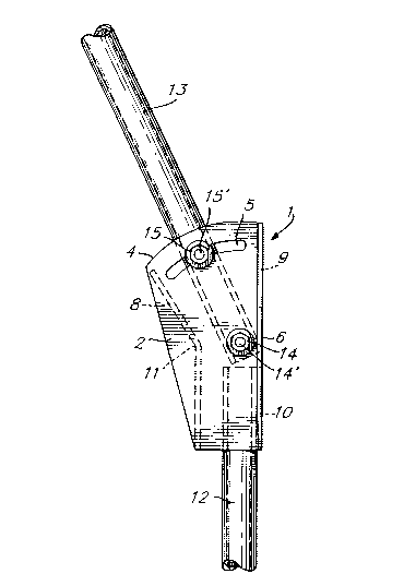
Figure 1 is a side, elevation view of a
bracket in accordance with the present invention;
Figure 2 is a top view of the bracket of
Figure l; and
Figure 3 is an enlarged, partial side
elevation view of the bracket of Figure 1 to which is
mounted the pole of a telecommunication antenna.
DETAILED DESCRIPTION OF THE PREFERRED EMBODIMENTS
As illustrated in Figures 1 and 2 of the
appended drawings, the preferred embodiment of the
bracket 1 of the invention comprises a pair of lateral
steel plates 2 and 3 which are symmetrical with
respect to a central plane parallel to these plates.
The shape of the plates 2 and 3 is shown in Figure 1.
In particular, each plate 2 and 3 has a semicircular
and inclined upper edge 4, as well as a semicircular
upper slot 5 parallel to the edge 4. The arcs of
circle defined by the edge 4 and slot 5 have a common
center on which is centered a hole 20. The vertical
rear edges 6 and 7 of the plates 2 and 3 are beveled.

,_ 2oll328
The lateral plates 2 and 3 are
interconnected through a set of three steel plates,
namely a front plate 8 and two rear plates 9 and 10,
welded to the lateral plates 2 and 3. As shown in
Figure 1, the front plate 8 defines an obtuse angle 11
and has a lower portion which is vertical. The rear
plates 9 and 10 are planar and rectangular, they
interconnect the beveled edges 6 and 7, are lying in
the same vertical plane one above the other, and are
spaced apart from each other by a given distance.
The bracket further comprises a vertical
pipe section 12 of which the upper end is inserted
between the lateral plates 2 and 3 and is welded to
the inner surfaces of these two plates. As
illustrated in Figure 2, the outer, cylindrical
surface of the pipe section 12 contacts the inner
surfaces of the plates 2, 3 and 10. The top edges of
the pipe section 12 and of the rear plate 10 are at
the same level, and the longitudinal axis of the
latter pipe section is parallel to the beveled edges
6 and 7.
Referring now to Figure 3 of the appended
drawings, the antenna comprises a pole 13 of which the
lower end is pivotally mounted to the bracket 1. The
pole 13 is typically a cylindrical tube made of
aluminum. More specifically, the lower end of the
pole 13 is introduced between the lateral plates 2 and
3, and a transversal bolt and nut assembly 14
traverses holes in the pole and the holes 20 in the

._, 2ol~3z8
latter plates. The pole 13 can therefore be rotated
about the pivot formed by the bolt 14' of assembly 14,
the spacing between the plates 9 and 10 providing
clearance for that purpose. The bolt and nut assembly
14 is therefore positioned on the center of the arcs
of circle defined by the edges 4 and the slots 5 of
the plates 2 and 3.
Another transversal bolt and nut assembly
1015 traverses holes in the pole 13 and the slots 5 in
the two plates 2 and 3. Accordingly, the bolt 15' of
assembly 15 slides into the slots 5 when the pole 13
is pivoted about the bolt 14'. In order to adjust the
position of the antenna, one has only to pivot the
pole 13 about the bolt 14', and as the antenna reaches
the desired position the bolt and nut assembly 15 is
tightened to lock the pole 13 and therefore the
antenna in this position.
20The bracket 1 can be installed on the end
of a metallic tower (not shown). For that purpose,
the pipe section 12 is fixed to the tower through
suitable fasteners (not shown). It is positioned
vertical using a level with its angular position about
its longitudinal axis selected to appropriately orient
the bracket 1. The last step in adju~ting the
position of the antenna is to rotate the pole 13 about
the bolt 14' and then to tighten the bolt and nut
assembly 15, as explained in the foregoing
description. The bolt and nut assembly 14 can then

` -
2(~328
also be tightened to increase the rigidity of the
fixation.
Of course, the pipe section 12 can be
fixed vertical on the tower with the plates 2, 3, 9
and 10 at the lower or the upper end thereof.
The bracket 1 in accordance with the
invention can be used to install on the top of a
metallic tower any type of telecommunication antenna,
in particular but not exclusively an antenna for
cellular telephony.
Although the present invention has been
described hereinabove with reference to a preferred
embodiment thereof, such an embodiment can be modified
at will, within the scope of the appended claims,
without departing from the spirit and nature of the
invention. In particular, the pipe section 12 can be
replaced by any other type of fastener suitable to
mount the bracket 1 on the metallic tower.

Dessin représentatif
Une figure unique qui représente un dessin illustrant l'invention.
États administratifs

2024-08-01 : Dans le cadre de la transition vers les Brevets de nouvelle génération (BNG), la base de données sur les brevets canadiens (BDBC) contient désormais un Historique d'événement plus détaillé, qui reproduit le Journal des événements de notre nouvelle solution interne.

Veuillez noter que les événements débutant par « Inactive : » se réfèrent à des événements qui ne sont plus utilisés dans notre nouvelle solution interne.

Pour une meilleure compréhension de l'état de la demande ou brevet qui figure sur cette page, la rubrique Mise en garde , et les descriptions de Brevet , Historique d'événement , Taxes périodiques et Historique des paiements devraient être consultées.

Historique d'événement

Description Date
Inactive : CIB de MCD 2006-03-11
Le délai pour l'annulation est expiré 2002-03-04
Inactive : Demande ad hoc documentée 2002-01-15
Inactive : Demande ad hoc documentée 2001-09-28
Lettre envoyée 2001-03-02
Inactive : Grandeur de l'entité changée 1999-02-25
Inactive : Lettre officielle 1998-09-09
Inactive : Inventeur supprimé 1998-09-09
Inactive : Lettre officielle 1998-09-09
Inactive : TME en retard traitée 1998-08-14
Lettre envoyée 1998-03-02
Accordé par délivrance 1995-08-22
Demande publiée (accessible au public) 1990-11-01
Toutes les exigences pour l'examen - jugée conforme 1990-08-23
Exigences pour une requête d'examen - jugée conforme 1990-08-23

Historique d'abandonnement

Il n'y a pas d'historique d'abandonnement

Historique des taxes

Type de taxes Anniversaire Échéance Date payée
Annulation de la péremption réputée 1998-03-02 1998-08-14
TM (brevet, 8e anniv.) - générale 1998-03-02 1998-08-14
TM (brevet, 9e anniv.) - petite 1999-03-02 1999-02-24
TM (brevet, 10e anniv.) - petite 2000-03-02 2000-02-10
Titulaires au dossier

Les titulaires actuels et antérieures au dossier sont affichés en ordre alphabétique.

Titulaires actuels au dossier
ROY TELECOMMUNICATIONS LTEE
Titulaires antérieures au dossier
GILLES ROY
MARC BERNIER
Les propriétaires antérieurs qui ne figurent pas dans la liste des « Propriétaires au dossier » apparaîtront dans d'autres documents au dossier.
Documents

Pour visionner les fichiers sélectionnés, entrer le code reCAPTCHA :


Pour visualiser une image, cliquer sur un lien dans la colonne description du document. Pour télécharger l'image (les images), cliquer l'une ou plusieurs cases à cocher dans la première colonne et ensuite cliquer sur le bouton "Télécharger sélection en format PDF (archive Zip)" ou le bouton "Télécharger sélection (en un fichier PDF fusionné)".

Liste des documents de brevet publiés et non publiés sur la BDBC .

Si vous avez des difficultés à accéder au contenu, veuillez communiquer avec le Centre de services à la clientèle au 1-866-997-1936, ou envoyer un courriel au Centre de service à la clientèle de l'OPIC.


Description du
Document 
Date
(aaaa-mm-jj) 
Nombre de pages   Taille de l'image (Ko) 
Abrégé 1995-08-21 1 25
Description 1995-08-21 7 208
Abrégé 1995-08-21 1 25
Dessins 1995-08-21 1 23
Revendications 1995-08-21 2 54
Dessin représentatif 1999-07-26 1 12
Avis concernant la taxe de maintien 1998-03-29 1 179
Quittance d'un paiement en retard 1998-08-19 1 172
Avis de rappel: Taxes de maintien 1998-12-02 1 118
Avis de rappel: Taxes de maintien 1999-12-05 1 119
Avis de rappel: Taxes de maintien 2000-12-04 1 121
Avis concernant la taxe de maintien 2001-04-01 1 178
Deuxième avis de rappel: taxes de maintien 2001-09-04 1 130
Avis de rappel: Taxes de maintien 2001-12-03 1 121
Taxes 1998-08-13 1 49
Correspondance 1998-09-08 1 7
Taxes 1999-02-23 1 110
Correspondance 2001-09-04 3 109
Correspondance 2001-12-03 3 254
Correspondance 1998-09-08 1 6
Taxes 2000-02-09 1 107
Taxes 1997-03-02 1 47
Taxes 1996-02-27 1 26
Taxes 1995-02-28 1 31
Taxes 1994-05-05 1 42
Taxes 1993-02-17 1 29
Taxes 1992-02-26 1 26
Correspondance reliée au PCT 1998-09-02 1 14
Correspondance de la poursuite 1993-08-19 2 47
Demande de l'examinateur 1993-02-24 2 83
Demande de l'examinateur 1993-09-30 2 58
Correspondance de la poursuite 1994-03-30 3 118
Correspondance reliée au PCT 1995-06-08 1 32
Courtoisie - Lettre du bureau 1995-01-18 1 14
Correspondance de la poursuite 1993-08-19 6 145
Courtoisie - Lettre du bureau 1993-11-02 1 18
Correspondance de la poursuite 1993-01-26 6 278
Courtoisie - Lettre du bureau 1993-02-04 1 17
Courtoisie - Lettre du bureau 1990-09-18 1 52
Correspondance de la poursuite 1990-08-22 3 97
Courtoisie - Lettre du bureau 1992-02-25 1 22
Courtoisie - Lettre du bureau 1991-11-27 1 26
Correspondance de la poursuite 1992-02-16 1 29
Correspondance de la poursuite 1990-10-31 2 65
Correspondance de la poursuite 1991-11-18 9 291