Note: Descriptions are shown in the official language in which they were submitted.
'~ ~ a ~
HYDROPHOBIC VENTING OF FREE LIQUID INK RESERVOIR PEN
Bac.kg_ound of_the_Invention and_Prior Art
The present invention is direrted to the field of
: relatively inexpensive dlsposable ink pens which nse a self
: co~talned supply ~of liquid ink. Such pen~ are of
w~despread use wherever a continuous steady flow of ink is
requlred and interruptlons, i.é. "skipping" in the line
;drawn by the pen! cannot be tolerated. Such applications
'
:: :
, . . ...
,: ~ , . . : ,
:, ~ :
~:; ' ' : ~: ~ '' ,
: : ,, ' '' :
- . : ,
2 ~
include, but are not limited to, computer driven plotter
pens. The present invention is particularly concerned with
a replaceable liquid ink pen useful as a plotter pen.
Prior art liquid lnk pens have a sealed reservolr
of liquid ink whlch ls provided with a capillary or channel
vent of small dimensions so as to prevent ink laakage
through the caplllary or channel vent. These pens deliver
ink to a writing media from the tip of the pen via the
capillary force of the pen nib and the media. As ink
supply in the reservoir is depleted, the pressure in the
reservoir drops until an air bubble forms at the lnterface
between the reservoir and the vent. The bubble enters the
reservoir and replaces the depleted ink with air,
lS momentarily relieving the pressure difference. This
process occurs throughout the life of the pen;
When the pen ls not in use, its storage
condltions may change. For example, the temperature of the
ambient air may decrease cau~ing the re~ervoir to cool with
a resultlng internal pressure drop which causes air to
bubble into the reservoir. Subsequent temperature rises
reverse the process and may cause movement of ink into the
vent1ng channel or venting capillaries if the orientation
of the pen is such that the ink in the reservoir covers the
end of the venting channel or capillaries. If the ~ir
expansion i9 sufficient, ink completely fills the venting
channel or capillaries followed by leakage out of the pen.
The same scenario occurs with decreases in ambient
pressure.
One solution to the leakage problem is to use a
fibrous filler ln the liquid ink reservoir. Such fillers
have an adverse effect on ink flow resulting in thin or
uneven lines, particularly when the supply of ink is
. , ~., :. .
: ~ . -
,
:. ' : . : :
~: , . - ~
2 ~
substantially depleted.
A maJor problem with using an air vent to control
ink flow in free liquid lnk reservoir pens is that
different inks have different viscosities, and thus
different sizes of vents are necessary to obtain ldentical
flow rates for each diPferent ink. One attempt to avoid
this problem is dlsclosed ln U.S. Patent No. 4,588,319
issued May 13, 1986 to Niemayer, which uses a foam flow
re~trictor positioned in the pen housing between the air
vent and the main ink reservoir. Ink leakage to the
outside of the pen through the capillary or channel vent~
due to pressure differentlals as discussed above, is not,
however, provided by the foam flow restrictor.
Summarv of_the In ention
It is accordingly the ob~ect of the invention to
provide a substantially leakproof free liquid ink reservoir
pen.
The present invention accordingly provides a free
liquid ink reservoir pen comprising:
a) a reservoir containlng a supply of
liquid ink;
b) a pen nlb attached to said reservoir for
delivering ink from said supply thereof to a writing
medium;
c) a vent for venting said reservoir to
atmosphere; and
d) a body of hydrophobic venting material
.
:: -
, :~ :'': i .
. ' -' ~ ' ; ' .
. .
' ~ ~
2 ~
arranged to prevent the flow of ink from said reservoir
through said vent to atmosphere, said hydrophobic venting
material permitting air flow into and out of said reservolr
through said vent to compensate for pressure differentials
S between the ambient atmosphere and the lpterlor of said
reservoir.
Unlike capillary and channel vented pens, air
flow to vent the reservoir is not restricted by bubble
generation. Air ventlng of the pens disclosed herein does
not regulate ink flow since the reservoir is es~entially
open to atmosphere.
Br ef DescriPtion of_ he Drawing
In the drawings wherein like reference numerals
designate 11ke parts:
Figure 1 i~ an elevation view in cross section of
20 a first embodlment of the invention showing the pen in its
vertical writing position;
Figure 2 ls a top plan view of the embodiment
- shown in Fig. 1:
Figure 3 is a vlew.similar to Fig. 1. of a second
embodiment of the present lnvention showing a vented bottom
reservoir wall;
30Figure 4 is a vertical cross sectional view taken
at lines 4 - 4 of Fig. 3;
Figure 5 is an elevation view in cross section of
a third embodiment of the inventlon showing the pen in an
1nverted position; and
.. . . .
- . . . . . . . .
,. . . . ~
: . : . . - : :. : : -
- ~ : :
.:
,, . . .. : - ~ ,
:: ' ~ ' . .
- 2~418~
Figure 6 is a graph comparing the ink flow
characteristics of the present invention with those of the
prior art.
s
Descri~tion of_the Prefe~rred Embodiment
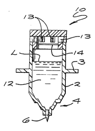
Figures 1 and 2 show an elongated pen reservoir
body 2 of cylindrical configuration having a retaining
collar 3 and a tapered tip portion 4 provided with a porous
of hollow pen nlb 6 centrally mounted therein. The upper
end of the reservoir body 2 is preferably closed by a vent
cap 10 which is press fit into the upper end of the
reservoir body 2 to define an ink chamber 12 therein. The
reservoir body 2 is conveniently made of clear plastic
material so that the color and amount of the ink therein is
easlly determined.
The upper end of the reservoir body 2 has a vent
in the form of one or more radlally dlstributed vent
~assageways 13 and a piece 14 of hydrophoblc venting
material disposed between the ink chamber 12 and the
passageways 13 therein to prevent flow of liquid ink
- through the passageways 13. The hydrophobic venting
material may be a generally flat sheet of material as shown
or may be a plug of material or any suitable shape so long
a~ it permits air to freely pass therethrough bu~ also
prevents passage of ink to thereby prevent leakage of ink
from the chamber 12. A presently preferred hydrophobic
venting material ls a porous plastic materlal sold under
the trademark GORETEX by Gore, Inc. of Elkton, Maryland.
Other materials believed suitable are porous
polytetrafluoroethylene materials such as TEFLON (Trademark
of Dupont Company).
'
:: . .
: . ' . ~' .: : -
.: ~ : ~ ~ - : -
: .. . -
o ~
Figures 3 and 4 show an embodiment like the
embodiment of Fig. 1, but which is also provided with a
vented wall 20 near the tlp portlon 4 of the pen. As
~hown, the vent wall 20 is planar and has a plurality of
vent bores 22 therethrough arranged in circular pattern
around the pen nib 6. An annular ring 24 of hydrophobic
venting material i8 dlsposed inside the ink chamber 12 in
tight engagement with the interior surface of the vent wall
20 whereby lnk in the chamber is prevented from leaking
between ring 24 and end wall 20 then through the vent bores
22 which are closed by the hydrophobic material.
Regardless of the orlentation of the pen, atmospheric
venting of the ink chamber through the hydrophobic material
and vents at the cap end or at the vent wall end of the ink
chamber takes place without leakage of the pen.
Flgure 5 shows a third embodiment of the
inventio~ ~imllar to the embodiment of Fig. 1, but in which
a conical plug 30 of hydrophob~c venting material extends
inwardly into the iDk chamber 12 from the vent cap 10.
Figure 5 is shown in inverted non-writing position with the
liquid level L of the ~nk of the filled reservoir as shown
slightly below the apex 32 of the conical plug 30 of
hydrophobic material. The air in th~ ink chamber 12 of the
Fig. 3, embodlment is thus permitted to pass back and forth
to atmosphere through conical plug 30 of hydrophobic
venting material regardless of the orientation of the pen.
Flgure 6 is a graph comparing ink flow
characteristics of the present invention with those of
filler reservoir pens of the prior art. As seen in the
graph, the amount of ink delivered to the media gradually
decreases as the ink supply is exhausted in prior art
filler reservo`ir pens. In comparison, the amount of ink
dellvered to the paper or other m~dia remalns substantially
:
",, .,~ ,,,, , , .. , .. ~ . . . :
. . ~ . .
.
- .
:: ~ ~ : .
:
2 0 1 1 4 8 ~
constant regardles~ of the amount of ink which has been
used for the free liquid ink vented pens of the invention.
Persons skilled in the art will readily
appreclate that varlous modifications can be made from the
preferred embodiment thus the srope of protection is
intended to be defined only by the limitations of the
appended claims.
~:
'
:
.
: , , : ,:- :
- , .
- : ~: :
,