Note: Descriptions are shown in the official language in which they were submitted.
2 ~
-
FLAT TOUCH SCREEN WORKPAD FOR A DATA PROCESSING SYSTEM
FIELD OF THE INVENTION
This invention relates to a workpad that serves as
both an input and an output (I/O) device for a data
processing system. More particularly, the invention
relates to a flat display device combined with a touch
panel and button switches which provide a generally
horizontal viewing and work surface, the button switches
being program interpretable and usable to emulate the
operation of mouse buttons, function keys and the like.
BACKGROUND OF THE INVENTION
Touch panels have been developed for use with cathode
ray tube (CRT) display devices, the combination being
connected to a data processor for use as both an input and
output device. An example of such a system is described
in U.S. patent 4,686,332-Greanias et el, "Combined Finger
Touch and Stylus Detection System for use on the Viewing
Surface of a Visual Display Device", said patent being
assigned to the assignee of the present invention. The
advantage of such a system is that a touch panel provides
user friendly interaction with a data processing system.
One disadvantage of such a system in accordance with the
prior art is that because the touch panel is placed on the
vertical viewing face of a CRT, the user has to reach out
in order to touch the panel or use this stylus. When the
MA9-89-015
- 2 0 ~ 7
user does this for an extended period of time, such action
becomes tiresome, uncomfortable and tedious.
The physical dimensions of a CRT make it difficult
to design a display havings a horizontal viewing surface
upon which a touch panel can be mounted. Further, a CRT
is rather bulky and heavy making it difficult to move the
touch input device to positions which are more convenient
or efficient for the user. Another disadvantage is that
the CRT display uses coaxial cables or wires. Such coax
wiring is relatively heavy and stiff which also detracts
from the ability to readily move the display device from
one position to another. Further, CRT displays consume
considerable power requiring the use of a separate power
cable. The CRT based devices therefore are operated at a
fixed location.
In addition, the use of touch input devices and the
attendant display screens have been limited by the
availability of computer programs. Typically, the touch
panels are used to select actions or graphic display
panels in response to a user touch on particular menu
selections displayed on the screen. Many more complex
computer applications, particularly for a personal
computer, have been written for keyboard or mouse pointing
device input. It would be an advantage to design a touch
input device which could emulate the input of a wide
variety of input devices, including the mouse and the
keyboard, to take advantage of the many existing
applications programs based upon such devices.
MA9-89-015 2
2 ~ 7
SUMMARY OF THE INVENTION
Improvements in the art of sensor and display
technology now make the implementation of a workpad
concept feasible. While prior art touch displays are
acceptable for short, casual use tasks, they may not be
feasible or suited for intensive use tasks. Recent
improvements in the optical qualities (brightness,
contrast, viewing cone) of flat panel displays, such as
LCDs, allow implementing a touch screen for use in a
horizontal orientation. This greatly improves the human
factors for applications involving extensive pointing,
drawing, or writing.
The design objectives associated with the design of
the invention are to provide a touch input device that is
a significant improvement over existing touch screens, as
well as other inputs devices in an office environment,
that meet the following requirements:
MA9-89-015 3
201 1 51 7
Input-
- detection of finger position
- detection of sty]us position for detail work
- spatial resolution as good as current mouse
devices
- temporal resolution adequate for handwriting
applications and mouse point-and-drag operations
- support for multiple value input at each touch
position, eg, mouse buttons 1 and 2
- operation without a separate keyboard for most
applications
Display-
- operation in office ambient lighting
- support for IBM~ VGA video standard
- support for at least 8 shades of gray
- adequate contrast and viewing angle for daylong
use
- support for simultaneous use of standard color
CRT
Physical Configuration-
- nearly horizontal orientation with adequate arm
support
- convenient laptop use for intensive thought
tasks
- flexible one cable attachment to computer
It is therefore an object of the invention to
provide a touch panel display device or workpad that
can be readily handled by a user and operated in a
variety of positions, including a substantially
horizontal position upon the users lap or upon a desk
top, as dictated by the convenience of the user and the
need for adequa~e arm support.
MA9-89-015 4
2 ~ 7
Another object is to allow a maximum freedom of
movement between the workpad and the rest of the data
processing to which it is connected thereby permitting its
use in positions or locations comfortable and efficient
for the user, including a standing position.
Still another object is to provide a high resolution
workpad that can be readily moved about due in part to the
use of a flexible coiled cable connected between the
workpad and a data processor.
Still a further object is to emulate a variety of
types of input from a single touch input device, including
touch, keyboard, mouse and gesture input data formats.
Another object is to provide a touch panel display
device that utilizes a liquid crystal display combined
with an overlayed touch panel that is actuated by either
a finger touch or a proximity of a stylus to the panel,
with additional switches or buttons which are program
controlled and may be used to emulated mouse buttons.
Briefly, in accordance with the preferred embodiment
of the invention, the above objects and advantages are
obtained by a light weight relatively flat workpad
connected by a flexible coiled cable to a personal
computer. A li~uid crystal display is mounted in the
workpad and has a rectangular viewing face overlayed with
a transplant touch panel. The stylus is connected to the
workpad and the touch panel is activated by either a
finger touch or by bringing the stylus into contact or
near contact therewith. Electrical controls are partially
MA9-89-015 5
2 ~ 7
._
mounted in the workpad and partially in the personal
computer. At least one button switch is mounted on the
workpad housing adjacent to the viewing surface and in
such a position as to be selectively actuated by hand of
the user while the other hand of the user is manipulating
the stylus or touching the touch panel. Under program
control, the switch can emulate a switch found on a mouse
pointing device, a function key or a keyboard.
DRAWI NGS
Fig. 1 is a top view of a workpad designed in
accordance with the present invention;
Fig. 2 is a side view of the workpad shown in Fig.
l;
Fig. 3 is an end view of the workpad shown in Fig.
l;
Fig. 4 is a schematic diagram of a data processing
system embodying the invention and showing one mode of
interaction therewith by a user;
Fig. 5 is a schematic cross sectional view through
the cable which connects the workpad to a personal
computer as shown in Fig. 4;
Fig. 6 is a block diagram of certain of the
electrical portions of teh invention;
Fig. 7 is a more detailed block diagram of the
computer to display channel of communication:
Fig. 8 is a more detailed block diagram of the
display to computer channel of communication; and
MA9-89-015 6
~ ig. 9 is a block disgram useful in understanding the
programmed operation of the button switches.
DESCR I PTION
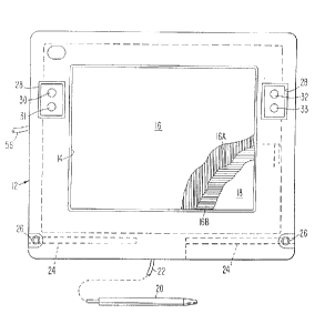
Referring now to the drawings, and first to Fig. 1,
a workpad 10 comprises a housing 12 provided with a
rectangular recessed window 14 that surrounds the edges
of a rectangular touch panel 16. Touch panel 16 is
transparent and overlays an LCD 18 which, because of the
rectangular window 14, provides a rectangular viewing
surface. The combination of the touch panel and display
is referred to hereinafter as a "touch screen" 19. Panel
16 includes a multiplicity of embedded, transparent
conductors 16A orthagonally positioned relative to a
multiplicity of conductors 16B. The number of
intersections of the orthogonal lines 16a and 16b
correspond substantially to the number of pixels in LCD
18. Touch panel 16 is constructed similar to the touch
panel described in the aforementioned patent 4,686,332.
A detection or pickup stylus 20 is connected by cable
22 to workpad 10 and is of a size similar to a pen or
pencil such that the stylus can be manually grasped and
moved about within constraints of the length of cable 22.
Cable 22 is flexible to facilitate such movement and use.
Stylus 20 has a tapered working end within which is
enclosed a pickup coil (not shown) of a size relative the
conductors 16 A and B that provides detailed resolution
greater than that encounter when a finger is used to touch
MA9-89-015 7
2 ~ 7
,
the panel, allowing the stylus to be used for work more
detailed than that obtainable by use of finger touch.
Housing 12 has two side opening recesses in which stylus
20 can be placed for storage. Housing 12 further has two
upwardly facing recesses to accomodate the tip of the
stylus whereby the stylus can be supported in a more
readily available position, such as shown in Fig. 2, when
not in use. Recesses 24 and 26 are lined with metal walls
to shield the tip of the stylus and prevent unwanted
pickup from the conductors 16 A and B when the stylus is
out of use and stored away. Recesses 26 are located in
the lower corners of housing 14 as viewed in Fig. 2.
Window 14 and touch panel 16 and LCD 18 occupy most
of the area of the top of workpad 10 and the housing
surrounding the window is in the form of a rectangular
annular frame, such frame having two laterally spaced
rectangular recesses 28 formed in the sides near the top
of such frame. Mounted in such recesses are four button
switches 30-33, there being two switches at each side.
The switches are round, when viewed as in Fig. 2, and are
substantially flat having a thickness approximately the
same as the depth of a recess 28. The switches are
designed to be manually actuated by the fingers of a user.
When used to emulate mouse buttons, the switches are set
up for both left handed and right handed operation where,
e.g., switches 31 and 33 are used as mouse button 1 and
switches 30 and 32 are used as mouse button 2. It is
expected that a right handed user would rest finger of his
MA9-89-015 8
~ 7
or her left hand on or near buttons 30 and 31 leaving the
right hand free to control the display cursor by use of
the right hand fingers or by a stylus held in the right
hand. An alternative implementation of the switches would
be to implement them as part of the touch screen by
providing an oversize display including areas not needed
for the normal display, and under program control,
outlining areas to be touched for actuation in the manner
of the mechanical switches. These buttons are single
pole, single throw, momentary action push button switches.
The buttons can be programmed in software to provide
various application specific functions. For example, the
buttons can be programmed to emulate the functions of
mouse button 1 and button 2 when depressed. They can be
programmed in software to operate as four independent
buttons or as two sets of parallel buttons. Momentary
action or latched action can also be defined by
appropriate software.
A tilt stand or support 34 is mounted on the
underside of housing 12 and includes two laterally spaced
arms 36 connected at one end to and mounted for rotation
about pivot pins 38. The other ends of the arms are
connected to and support a cylinder 40 of a soft plastic
or rubber that extends between the two arms. Together,
arms 36 and cylinder 40 form a U-shaped support 34 which
is moveable between the full line position shown in Fig.
2 to the dotted line position. In any position along such
path of movement, support 34 is frictionally held in place
MA9-89-015 9
2 Q ~
'_
and will not give under the weight of workpad 10. When
support 34 is in the full line position, cylinder 40 does
not extend beneath the bottom flat surface 44 of housing
12. When moved to any other position, support 34 will
support workpad 10 on a work surface at an angle up to
about 35 degrees. The work surface could be a desk top
or the lap of user. The bottom surface 44 and the top
surface of housing 12 are flat and parallel to one another
but spaced apart by the depth of the housing or workpad.
When the bottom surface 44 is resting on a flat horizontal
surface, the upper surface 42 is also horizontal, as is
the touch panel and viewing face of the LCD so that the
viewing face is exposed for view in such position.
It should be appreciated that when used on the lap
of the user, support 34 may or may not be used. Further,
the support could be extended downwardly and grasped
between the knees of the user to provide a more secure
support than that provided merely by resting workpad 10
on the user's lap. The overall dimensions of workpad 10
are approximately 11" by 14" by 2" (so that it is of a size
that can be readily handled by a user and supported on a
lap. Relative brightness and contrast control knobs 50
and 52 are mounted on the underside of housing 12 and
exposed for manual rotation from the side thereof. The
weight of workpad 10 is 1.8 Kg.
Referring to Fig. 4, workpad 10 is connected to a
personal computer 60 through a single cable 56. Computer
60 comprises a system unit 62, a display 64 and a keyboard
MA9-89-015 10
2~
' -
66. This figure also shows a user 70 supporting workpad
10 on the user's lap while the personal computer is
supported on a table or desk top 72 at a distance from the
user. Cord 56 has an extensible medial coiled portion 74
connected between two non-coiled ends 76. The extended
length of cord 56 is preferably sixteen feet allowing the
user to move the workpad to many different positions that
are comfortable. Quite obviously, such length is
illustrative only and other lengths can be used.
As shown in Fig. 5, cable 56 comprises an outer
insulating sheath 80 surrounding two insulated wires 82
and 83 and two triple twisted wire cables 84 and 85. These
latter cables house insulated wires 86, 87, and 88, and
90,91 and 92. Wires 82 and 83 provide 0 and -5 volt power,
wires 88 and 91 provide +12 and -12 volt power, wires 86
and 87 are signal wires for balanced transmission from the
workpad to the computer, and wires 90 and 92 are signal
wires for the balanced transmission from the computer to
the workpad. Thus, all the needed conductors for carrying
the necessary power and signals to operate workpad 10 are
contained in a single cable.
Referring now to Fig. 6, mounted within housing 12
of workpad 10 are various electrical circuits which obtain
power through cable 56 and which are operated under the
control of personal computer 60. Display 18 is connected
through line 102 to an LCD controll 100 which in turn is
connected through line 104 to a bus 106. Interface 108
ic connecte to bus 106 and to cable 56 whereby operation
MA9-89-015 11
of display is done with signals and commands sent over
line 56 from teh computer. Touch sensor 16 is connected
to a sonse mode frequency measurement circui 110 and to a
wire select multiplexer 114. A sensor driver 112 connects
between mux 114 and bus 106, and operates to detect when
and where a finger touches the tough screen. A button
status circuit 116, described in detail below, is
connected to the button switches 30-33 through line 117.
Line 22 from te stylus is connected to a stylus input
circuit 118 which in turn is connected to a stylus mode
signal strength measurement circuit 120, the latter being
connected to bus 106.
A touch panel adapter card 126 is mounted in the
computer and has an interface 122 connected to cable 56.
A video processor 127 is connected to interface 122 andf
to the auxiliary video slot 128 of computer 60. Computer
60 includes stardard items such as a CPU 132, ROM 134,
Disk 136, keyboard 66, display 64 and a memory 138 which
stores an operating system 140 and application program
142 for execution thereof. Card 126 also includes a bus
connected to interface 122 and to a ROM 144, RAM 146,
control processor 148 and I/O controller 150. Controller
150 is connected to bus 130 through line 152.
As shown in Fig. 7,interface 122 includes a RAM 226
which receives and stores video signals and outputs 1/4
at a time to a multiplexer (mux) 224 so that the video
display re~uires four frames of signal to fully change the
display. Mux 222 provides signals to a parallel to serial
MA9-89-015 12
converter 220 which outputs to a non return to zero
invert(NRZI) circuit 214 and a transmitter (trans) 216.
Signals are transferred over lines 90 and 92 of cable 56
from trans 216 to a receiver (rcvr) 214. The signals then
pass through a serial to parallel converter 210, 5B/4B
decoder and a demultiplexer 200. The latter provides
separate signals on lines 202, 204 and 206 send various
signals tothe display such as control, status query,
sensor driver commands and video signals.
The signals being transmitted from the display to the
computer pass through the channel shown in Fig.8 which is
similar to the channel shown in Fig. 7. Input signals on
lines 242, 244, 246 and 240 are inputted to MUX 240 and
pass thru encoder 250, converter 252, NRZI circuit 254,
rcvr 256, lines 86 and 87, trans 258, circuit 260,
converter 262, decoder 264 to a mux 266 where they are fed
to the computer.
Fig. 9 generally shows the manner in which buttons
30-33 are operated under program control. The button
switches are connected respectively to a series of change
of state registers 300 which in turn are connected to
button state registers 302. Upon actuation of any switch,
it will enable its associated register and send to the
associated register 302 a code specifically identifying
the switch that was actuated and an interrupt signal will
be sent over lines 117 to the computer 60. An interrupt
handling routine will then query state register 302 and
obtain therefrom the code signifying which switch was
MA9-89-015 13
actuated. Deactuation of a switch will also cause an
interrupt. Memory 138 stores the programs for
interpreting the switches which will include device driver
and emulation routines 304, an event generator,
enviornment dependent routine 306 and application software
308. The emulation routines 304 can interpret the
switches to represent mouse buttons or functions keys to
enable the workpad to be used with application programs
written for such support. Alternately, the application
software itself 308 can interpret the keys directly.
It should be apparent to those skilled in the art
that many changes can be made in the details and
arrangements of parts without departing from the scope of
the invention as defined in the appended claims.
MA9-89-015 14