Note: Descriptions are shown in the official language in which they were submitted.
20 1 17 20
40002-1027 -1-
BATTERY IN A VACUUM SEALED ENVELOPING
MATERIAL AND A PROCESS FOR MAKING THE SAME
Background of the Invention
1. Field of the Invention
The present invention rE~lates to the manufacture of
battery assemblies, and more particularly solid state
batteries maintained in a protective material to exclude
air, water and other gasses to pi:otect the battery against
physical abuse to increase its shelf life. The battery
assembly is produced by surrounding solid state battery
components with an enveloping material and sealing the edges
of the material around the components in a vacuum
environment.
2. Description of the Prior Art
Presently there is a high level of interest in
industry in designing thin layer solid state batteries,
particularly lithium anode cells., These batteries include a
lithium anode, a transition metal. oxide polymer composite
cathode, and a solid or liquid electrolyte which includes a
dissolved lithium salt. Examples of such batteries are set
forth in U.S. Patents 4,303,748 t:o Armand, 4,589,197 to
North, 4,228,226 to Christiansen and Canadian Patent
Application Numbers 607,948 filed August 10; 1989 and
581,609 filed October 28, 1988.
A principal object of these batteries is to make
them as thin and compact as possible while still satisfying
market needs in terms of storage capacity, current density,
shelf-life and the like.
_. ~~~.~7~0
40002-1027 -2._
A problem in achieving this object resides in the
fact that these batteries must be moisture impermeable as
some of the components are very hygroscopic and can absorb
water and gasses which can ruin the battery in less than a
few hours. Additional problems have included accessing
current from the battery once the components of the battery
have been sealed, and the inabi:Lity of such batteries to
withstand the rigors of transportation, insertion and use
into products.
Attempts have been madE~ in the art to remedy some
of the above described problems.. For example, U.S. Patent
No. 4,502,903, assigned to Polai:oid teaches the construction
of the anode and cathode assemblies prior to sealing in a
controlled atmosphere that is relatively inert to lithium
and free of water, e.g. in dry air at a relative humidity of
not more than 1 to 2 percent. This patent also teaches
sealing of the edges of the battery unit under vacuum by
heat and pressure.
U.S. Patent No. 9,756,717, also assigned to
Polaroid teaches the sealing of the battery component edges,
under vacuum with the aid of heat and pressure. The sealed
battery is assembled on a card stock base and is overwrapped
with a layer of inert, chemically stable material which
serves primarily to prevent mechanical interference with
underlying components during they early stages of
construction of the battery. At. a later stage of
construction, this overwrap layer is sealed under a vacuum
using heat and pressure. Examples of overwrapping materials
include polyethylene, paper, glassine and paper-foil
laminates. This arrangement is taught with respect to a
LeClanche cell.
40002-1027 -3-
Although the above described batteries alleviate
some problems, they are deficient with respect to nonaqueous
cells as they provide limited protection against
-__ .
environmental contamination, pa:rticularly at the areas of
sealing. Accordingly, there exists a need in the art for a
battery which is stable for extended periods of time and is
resistant to mechanical shock or water or air degradation.
Definitions
The term "battery" can include a single cell, or a
plurality of cells connected in either series or parallel
fashion to furnish electrical current. The term "cell"
includes an anode layer, cathode' layer, electrolyte layer,
and a pair of electrically conductive terminals; or a
plurality of these layers connecaed in bifaced, bi-polar, or
other cell configuration design:. known in the art.
In the present invention, more than one battery may
be incorporated between the sheets of protective material
and more than one cell configuration may be utilized in each
of the batteries so incorporated.
Summary of the Invention
In accordance with the present invention, a battery
assembly comprising a solid state battery maintained in a
protective material is provided. The protective material
functions to exclude air and water, provide rigidity and
protect the battery during physical handling to promote the
shelf life of the battery.
In accordance with one embodiment, the battery
assembly comprises a laminar battery including an anode
layer, an ionically conductive electrolyte layer, and a
cathode layer, the electrolyte layer being interposed
....,
40002-1027 -4._
between the anode layer and the cathode layer and the layers
assembled to form an electrical cells a pair of electrically
conductive terminals in electrical contact with the anode
layer and the cathode layer: anti a protective sheet
material enveloping the laminar battery the sheet material
being heat-sealed at the periphE:ry of the laminar battery
and about the terminals to exclude air and moisture and the
terminals extending from or being accessible through the
protective sheet material for connection to a device which
is powered by the laminar battei:y.
It is preferable that t:he laminar battery is a
lithium thin cell battery. Further, the protective sheet
material may take the form of any number of configurations.
The material is typically a mult:i-layered material including
one or more heat sealable polymeric layers and one or more
moisture and gas impermeable layers and optionally, one or
more outer protective polymer layers. Where the
multilayered protective sheet material does include one or
more outer protective polymer layers, the outer protective
polymer layer or layers will also function to cover or fill
any microscopic holes that may exist in the moisture and gas
impermeable layer, providing a greater than expected air and
water occlusion capability. Alternatively, the protective
sheet material may consist of a single layer as opposed to a
multilayered material if the single layered material is able
to provide all of the functions required of the multilayered
film.
Also, in accordance with the present invention a
method is provided for producing the battery assembly. The
method comprises the steps of inserting a finished thin cell
laminar battery including an anode layer, an ionically
conductive electrolyte layer, a cathode layer and a pair of
electrically conductive terminals in electrical contact with
said anode layer and said cathode layer between sheets of a
40002-1027 -5-
protective material and sealing the material with heat and
pressure such that external access to said pair of
electrically conductive terminals is provided. In
accordance with one embodiment, the sealing step is
conducted in a vacuum atmospherE:.
Thus, one object of the' present invention is to
provide a battery assembly including a laminar thin cell
battery which is less susceptible to degradation from water,
air and physical shock and has an extended shelf life.
Another object of the present invention is to
provide a method for producing a thin cell laminar battery
assembly including a laminar thin cell battery which is less
susceptible to degradation from water, air and physical
shock and has an extended shelf life.
Other objects and features of the present invention
will become apparent to those skilled in the art as the
disclosure is made in the following description taken in
conjunction with the accompanying drawings.
Brief Description of the Drawings
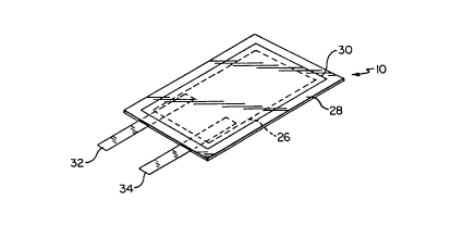
Fig. 1 is a perspective view of a battery assembly
showing a laminar thin cell battery in phantom enveloped by
a heat-sealed moisture impermeable multilayered sheet
material embodying the teachings of the instant invention
Fig. 2 is an exploded perspective view of a laminar
thin cell battery which may be used in accordance with the
present invention.
Figs. 3(a)-(b) show one method for producing an
alternative laminar battery assembly of the present
invention.
40002-1027 _6_
Fig. 4 is a cross-sectional schematic elevational
view of the battery of Fig. 3, wherein the battery is
inserted into a protective material.
Fig. 5 is an alternative battery assembly embodying
the teachings of the instant invention.
Description of the PrE~ferred Embodiment
In describing the invention illustrated in the
drawings, specific terminology will be resorted to for the
sake of clarity. However, the invention is not intended to
be limited to the specific terms so selected, and it is to
be understood that each specific: term selected includes all
technical equivalents which operate in a similar manner to
accomplish a similar purpose.
As illustrated in Fig. 1, the present invention
comprises a battery assembly 10, including a thin cell
laminar battery 26, shown in phantom, enveloped by a
multilayered air and water occlusive protective sheet film
material 28 which is heat sealed. around its periphery 30.
Connected to battery 26 are electrodes 32 and 34, which, as
will be discussed in greater detail with respect to Fig. 4,
are respectively electrically connected to the anode and
cathode of battery 26.
While batteries in accordance with this invention
may be of any desired electrochemical type, such as nickel
cadmium, nickel hydroxide, LeClanche, or lead acid, for
purposes of illustration and in accordance with a preferred
embodiment, the battery is of the lithium anode type.
Laminar thin-cell batteries containing lithium
anodes are known to the art, and those skilled in the art
will appreciate that the laminar batteries can include a
single cell, or a plurality of cells. Furthermore, the
201 1720
40002-1027 _7_
cells also can include various constructions such as
bifaced or bipolar cell designs. Other examples of cell
constructions include a jelly roll or a fan folded laminate
strip design, both of which are illustrated in Canadian
Patent Application Serial No. 60'7,948 filed August 10,
1988.
Referring to Fig. 2, battery 26 is a cell laminate
which includes an anode 12, first and second layers of an
ionically conductive electrolyte 14, 16 which contact anode
12 on opposite sides respectively, and first and second
cathode layers 18, 20 which contact the sides of electrolyte
14 and 16 which are not in contacts with anode layer 12.
Current collectors 22 and 24 respectively contact the sides
of cathode layers 18 and 20 which are not in contact with
electrolyte layers 14 and 16. The laminate shown in Fig. 2
is actually a bi-faced structure to maximize the use of
anode 12.
The materials used for forming the different layers
of battery are known in the art. For example, in one
preferred embodiment, battery 26 comprises a portion of a
secondary cell having an alkali metal foil anode 12 having a
typical thickness of about 100-150 microns, the ionically
conducting polymeric electrolyte layer 14 and 16 containing
an ionizable alkali metal salt having a typical thickness of
about 10 to 75 microns, cathode layers 18 and 20 including a
finely divided transition metal oxide having a typical
thickness of about 50 to 100 microns, and current collectors
22 and 24 which typically take the form of metal foils
having a typical thickness of about 5 to 25 microns.
In a particularly effective embodiment, anode 12
comprises a lithium foil, electrolyte layers 14 and 16
comprise a radiation polymerizable compound, the cathode
layers 18 and 20 comprise a composite of finely divided
40002-1027 -g..
vanadium oxide (V6013), carbon black or an electronically
conductive polymer and a solid electrolyte material, and the
cathode current collecting layers 22 and 24, comprise
nickel, stainless steel, aluminum foils, metal coated
polymers or electrically conductive polymeric materials such
as a thin film of polyethylene t.erephthalate having
electrodeposited thereon a layer of nickel metal.
More specifically, a typical anode material 12 is
lithium foil, an alloy of lithium, or lithium coated foil
such as nickel or copper foil having a layer of lithium
deposited on its front or front and back surfaces. Lithium
is preferred because it is very electropositive, passivates
and is light in weight. When using lithium materials as
anode layers to produce a laminar battery because of their
high reactivity, it is necessary to maintain the lithium
materials in a water and air free environment to prevent any
undesirable chemical reaction from occurring.
Electrolyte layers 14 and 16, which are sonically
conductive in nature, may be formed by preparing a mixture
of a liquid monomeric or prepolymeric radiation
polymerizable compound, a radiation inert sonically
conducting liquid, and an ioniza:ble alkali metal salt. The
alkali metal salt is preferably ~~omprised of a lithium salt,
such as LiCF3S03, LiAsF6, LiC104, Liar, LiI, LiB04 or LiPF6.
Radiation inert sonically conducvtive liquids are preferably
bi-polar aprotic solvents and include propylene carbonate,
-butryrolactone, dimethoxyethane, 1,3-dioxolane and
2-methyl-tetrahydrofuran. Radiaition polymerizable compounds
may be obtained by reacting a polyethylene glycol with
acrylic or methacrylic acid. Other examples include
acrylated epoxies, e.g., bisphenol A epoxy diacrylate,
polyethylene acrylates, copolymers of glycidyl ethers and
acrylates or a vinyl compound such as N-vinylpyrrolidone.
2Q~~~~~
40002-1027 -g._
The monomers which are selected do not substantially
adversely react with the anodic metal after polymerization,
as the anodic metal tends to be highly reactive. Other
electrolyte materials which are not radiation curable may
also be used in accordance with the present invention such
as solid electrolytes or electrolytes comprising a solid
solution of an alkali metal salt: in a polymeric matrix such
as LiC104/PEO electrolytes.
The cathode layer comprises a metal oxide
intercalation compound, an electrically conductive material
such as carbon or metal particles, and an electrolyte
material.
While V6013 is the preferred active material for
cathode layers 18 and 20, the active cathode component may
alternatively include metal chalcogenides such as NbSe3,
V205, Mn02, TiS2, Mo02, MoS3. Cr306, LixV308, V308, VS2.
NbSe2, FeOCl, CrOBr, TiNCl, ZrNCl, HfNHr, NiS2, FeS2, FeS,
NiS, NiS3, W02, or electronically conducting organic
polymers such as polypyrrole and. polyacetylene.
Other appropriate materials for the cathode current
collecting layers 22 and 24, besides metal foils are
conductive metals, conductive polymers, metal coated
polymers, screens, grids, foamed metals and the like.
The battery is produced by laminating the
respective layers together to form a unitary structure. The
lamination process may include coating the cathode layers
18, 20 and the electrolyte layers 14, 16 onto the cathode
current collecting layers 22 and 24 by doctor blade
continuous casting, solvent evaporation technique, extrusion
or other coating methods.
Although battery 26 is referred to as cell
laminate, it should be noted that there are in fact two
cells in the strict sense of the term, each having a cathode
~4~~7~~
40002-1027 _1~~_
in an ion exchange relation with a commonly shared anode.
Where the anode material is lithium foil, a substantial
economic savings is realized when the lithium foil is
commonly shared by dual electrolyte and cathode layers,
although those skilled in the art will appreciate that the
present invention could be constructed with a single anode
layer in an ion exchange relation with a single cathode
layer if desired. The electrochemical cell shown in Fig. 2
will function as a single cell if the two cathode layers 20
and 18 are always joined by a single cathode current
collecting substrate or are otherwise joined electrically.
Figs. 3(a) and 3(b) show the steps for
manufacturing an alternative battery similar to that shown
in Fig. 2.
Referring to Fig. 3(a), laminate assembly 100
includes current collecting substrate 124, which is
overcoated with a layer of cathode material 120, which in
turn is overcoated with a layer of electrolyte material 116.
Cathode 120 and electrolyte compositions 116, if
polymerizable, are then partially or totally cured by heat
or exposure to radiation. If they are solvent based
compositions, they are set by drying.
Lithium anode 112 is placed onto approximately one
half of electrolyte 116. The length of lithium anode 112 is
less than one half of the length of electrolyte 116 to
enable electrolyte 116 to be folded over anode 112 as will
be discussed with respect to Fig. 3(b). Electrically
conductive terminal 132 is then placed onto anode 112.
Terminal 132 is preferably a flat. metal or metal wire.
Suitable materials include copper, nickel, other conductive
metals, conductive polymers and rnetal coated polymers.
Where terminal 132 is copper, a strong bond is formed
between terminal 132 and the lithium anode 112 and no
adhesive is required to adhere the two elements together.
2~:~W~. ~~;~
40002-1027 -l:l-
As shown in Fig. 3(b), the laminate assembly 100 is
folded longitudinally upon itsel'~f along axis A-A to cause
electrolyte 116 to surround anode layer 112. Anode layer
112, should have a smaller length than the length of one
half of electrolyte layer 116 to ensure that the anode layer
112 does not contact cathode layer 120. Alternatively,
instead of folding laminate assembly 100 longitudinally
along axis A-A, assembly 100 could be cut along line B-H, or
originally fashioned in the two such similar sections, and
the two sections placed one upon the other to form an
assembly very similar to that of Fig. 3B so long as the
current collector layer 124 is made electrically continuous
between its upper and lower halves to utilize the electrical
energy of both the upper and lowrer cells.
When folded along axis A-A, despite retaining
flexibility, there may exist some deterioration in the
integrity of the layers at the fold line. This will not
affect the operation of the cell. Even if the layers do not
remain continuous at or about th.e fold line, the cell will
continue to function, as it is in essence a dual cell design
comprising an upper cell and a lower cell which share a
common anode. As indicated above, as long as the current
collector layer 124, links the upper and lower cathode
layers 120, both the upper and lower cells will function
even if there is some degradation of the electrolyte layer
116 and/or cathode layer 120, at or about the fold line.
Still referring to Fig. 3(b), a second terminal 134
is attached at one end to the outside of cathode current
collecting layer 124 by any means known in the art such as
applying electrically conductive adhesives, soldering or
spot welding. Electrode 134 is of a length sufficient to
permit the end not attached to protrude from beyond cathode
current collecting layer 124. Electrode 134 is made from
the same materials as electrode 132.
26:~~ ~
40002-1027 -1~!-
The cell laminate is then pressed or rolled
together to assure uninterrupted contact between the layers,
and taken together constitutes a~ battery collectively
referred to as Device A. Where cathode 120 and electrolyte
compositions 116 are polymerizable but have been only
partially cured, the compositions will retain flexibility to
permit folding with minimal deterioration at or about the
fold line. Additionally, the partially cured cathode 120
and electrolyte 116 layers will also exhibit a tackiness
that will cause the layers to adhere to one another and to
anode layer 112. This can additionally provide a more
intimate contact between the layers. The partially cured
polymerizable components may then be completely cured.
The cathode current collector layer 124 may be
designed to extend on the two parallel sides adjacent and
perpendicular to the fold line beyond the cathode material
layer 120 thereon, so that a bead of adhesive material may
be applied at or near the edge of the perimeter of the
interior surface of cathode current collecting layer 124.
In this manner, when laminate assembly 100 is folded onto
itself, the bead of adhesive will assist in securing
assembly 100 together until it is ultimately enveloped by a
heat-sealed moisture impermeable multilayered film.
Additionally, the individual layers of laminate
assembly 100 may be optionally slit at or about the fold to
assist in maintaining laminate assembly 100 as a unitary
structure by reducing its tendency to separate at the fold.
Device A is not completely resistant to
environmental attack. This is because cathode current
collector 124 typically contains interstitial apertures
having diameters of 10 microns or more through which
atmospheric contaminants, primarily air and water, may enter
and destroy device A. Therefore, device A is inserted into
a protective material and sealed as illustrated in Fig. 4.
201 1720 y
40002-1027 -13-
Fig. 4 shows a completed laminar battery assembly
designated by element 125. Assembly 125 includes laminar
battery device A, which is enveloped in a heat sealed'
moisture impermeable multilayered material represented by
elements 128 and 129 except for electrodes 132 and 134,
which slightly protrude from beyond material 128 and 129 to
enable connection of the assembl~t to an external device.
To manufacture the assembly shown in Fig. 4, while
maintaining an oxygen and moisture-free environment, device
A is placed between two sheets of the multilayered material
128 and 129 so that the sheets o~: material 128 and 129
completely surround device 100 except for electrodes 132 and
134, which protrude from beyond sheets 128 and 129. Each of
the four edges of the respective sheets of material are then
heat sealed to fuse the edges of the respective materials to
each other.
Sealing is accomplished by utilizing a Multivac
Vacuum Packing Machine from Sepp. Haggenmueller, KG Allgau,
W. Germany, which operates by utilizing heated platens which
are maintained at sufficient heat: and pressure to melt and
seal the polymeric edges which envelop the battery device.
For example a temperature of 100'C to 200'C at a pressure of
20-40 psi is typically used.
In practice, each pair of respective edges desired
to be sealed together are inserted between the two heated
platens and the sealing apparatu.~ is actuated to cause the
platens to move towards each other until the edges to be
sealed are in intimate contact. Pressure and~heat are
applied to the edges for a sufficient time period ranging
from about 1 second to about 5 seconds. The sealing
procedure is repeated for each of the other three pairs of
edges to be sealed to produce an assembly such as shown in
Figs. 1 and 4. Alternatively, up to all sides can be sealed
40002-1027 -lg;-
at once. Particular care must be utilized when sealing the
edges containing electrodes 132 and 134 to prevent them from
inadvertently breaking off during the sealing process.
However, a sufficient pressure must be applied to the edges
to seal around the electrodes to ensure an air and water
impermeable seal.
A further feature is that the sealing operation be
conducted in a vacuum atmosphere having a pressure as low as
possible, i.e. 4 to 40 mm Hg. The sealing under a vacuum
accomplishes several purposes. When the sealing operation
has been completed, the vacuum enables the multilayered
material to tightly adhere to the laminar cell to prevent
the cell from moving within the sealed enclosure and to
prevent delamination of the component layers. As a result,
the battery assembly is much more resistant to physical
damage caused during shipment and transportation. Further,
the tight adhesion of the multilayered material to the cell
enables the surface area of the battery to be maintained in
a minimal volume. Accordingly, this enables the production
of a small, thin battery.
The primary purpose of multilayered material is to
effectively envelop device A and to protect device A from
oxygen or moisture. An example of one material suitable for
use is shown in Fig. 4. Multilayered film materials 128 and
129, having an overall thickness of approximately 100
microns, include a first inner insulating, adhesive, heat-
sealable layer 142 and 144 a second thermoplastic layer 146
and 152 a third layer 148 and 1:54, consisting of an air and
water occlusive metal foil: and a fourth outer protective
layer 150 and 156, consisting essentially of a polyester
polymer, i.e. polyethylene terepllthalate. Primer and/or
adhesive films required to bond one layer to another, not
pictured, are utilized when necessary.
20 1 1720
40002-1027 -15-
The first inner thermoplastic layer 142 and 144 has
an approximate thickness of 25 to 50 microns, and functions
as an electronic insulator, a heat-sealable material and as
an adhesive between dissimilar surfaces. Electrical
insulating properties are required in this first inner layer
142 and 144, because as electrodes 132 and 134 extend from
device A a direct short would be produced across the metal
foil layer 148 and 154 if both electrodes were permitted to
directly contact metal foil layer 148 and 154.
This first inner layer 142 and 144 must also be
sealable upon the application of pressure and heat, at
sufficiently low temperatures and pressures so as not to
degrade device A. When the sealing operation is performed,
first inner layer 142 and 144 becomes fusible to enable
upper and lower surfaces 128 and 129 of the multilayered
film to be sealed together. On the edge from which
electrodes 132 and 134 will protrude, the heat-sealable
material must flow around the electrodes to achieve a
continuous seal between the upper and lower surfaces of the
multilayered film 128 and 129 and the electrodes.
Additionally, first inner layer 142 and 144 must
also possess an adhesive quality that will enable it to bind
together the dissimilar surfaces consisting of electrodes
132 and 134, and the second thermoplastic layer 146 and 152,
(or between electrodes 132 and 134 and the third metal foil
layer 148 and 154, in the event that a second thermoplastic
layer 146 and 152 is not included.)
Examples of suitable materials for the first inner
layer include a copolymer of ethylene and acrylic acid,
Surlyn (an extrudable ionomer resin which is defined as a
metal salt of an ethylene/organic acid copolymer available
from DuPont* Company of Wilmington, Delaware, hereinafter
designated "Surlyn"), and any other suitable materials known
* Trademark
~~_~~ i.'~~D
40002-1027 -16-
in the art. Ethylene and acrylic acid copolymers and Surlyn
are preferred because each exhibits the necessary
insulating, heat-sealing and adhesive properties discussed
above. The amount of heat and pressure required to seal the
multilayered film 128 and 129, wherein the first insulating
layer is ethylene acrylic acid wall vary depending upon the
chosen thickness and composition of all layers in the
multilayered film 128 and 129. I~owever, as a general
approximation temperatures in the range of 100-200'C are
required, as well as pressures o~' approximately 20-40 psi
for a time period of approximate:Ly 1-5 seconds where the
ethylene and acrylic acid copolyrner is about 25 microns
thick.
Caution must be exercised with the choice of
composition of the first inner layer 142 and 144, and with
the amount of heat and pressure t:o be applied. The first
inner layer 142 and 144 must be permitted to flow, but not
to achieve so high a degree of l~.quidity that the
composition will escape from the area wherein sealing is
desired, or that will permit the electrodes 132 and 134 to
traverse through the first inner layer 142 and 144 and the
second thermoplastic layer 146 and 152 to cause the
terminals to simultaneously contact the metal foil layer 148
and 154 and create a short.
From Fig. 4, it will be obvious to those skilled in
the art that the first inner layer 142 and 144 needs to
exhibit the ability to act as an adhesive between dissimilar
surfaces only along the edge from which the electrodes 132
and 139 protrude, and specifically only in the area bounded
bY the electrodes 132 and 134. Therefore, in another
embodiment of the present invention, the first inner layer
may be limited to the area at or about the electrodes. In
still another embodiment, the material which acts as an
adhesive may be coated, primed, or otherwise deposited on
40002-1027 -17-
electrodes 132 and 134. In either embodiment, the
additional layer provides both insulating and heat sealing
capabilities throughout the remainder of the inner surface
of the multilayered film.
Where the first inner layer 142 and 144 provides
all necessary insulating, heat sealing and adhesive
properties, the second thermoplastic layer may be omitted.
However, where the first inner layer 142 and 144 is provided
only in or about the area bounded by electrodes 132 and 134,
the second thermoplastic layer 7.48 and 154 is required in
order to provide both insulating and heat-sealing abilities
throughout the remainder of the inner surface of the
multilayered film. Even where t:he first inner layer 142 and
144 provides all needed properties, additional benefits are
derived from the inclusion of the second thermoplastic layer
146 and 152 in that additional mechanical and chemical
protection is provided and in that this type of multilayered
film is commercially available, such as product I.D. #KSP-
150-IMH from Kapak Corporation of Minneapolis, Minnesota
which, while lacking the required adhesive properties
described above, does provide insulating and heat-sealing
capability.
Still referring to Fig.. 4, second thermoplastic
layer 146 and 152 is utilized to exhibit these properties.
Suitable second thermoplastic layer materials include
polyethylene and polypropylene.
It is the purpose of the third layer 148 and 154
and fourth outer protective layer 150 and 156 to provide a
barrier for excluding air and water from the battery and to
provide rigidity to protect the battery during physical
handling.
Where the third metal layer contains small
(approximately 10 micron) holes which permit air and water
201 1720
40002-1027 -18-
to contact the battery, the fourth outer polymeric
protective layer will cover or plug those microscopic holes,
providing additional air and water occlusion protection. In
some cases two metal layers separated by a bonding film may
be needed to provide sufficient air and water occlusion.
In the preferred embodiment, the third layer is
preferably a metal such as aluminum foil and the fourth
outer protective layer is a polymeric material such as
polyethylene terephthalate.
Protective sheet material comprised of multilayered
films, is available commercially. For example, product
number 41748U30 available from Bell Fibre Incorporated, is a
five layered film consisting of a first layer of Surlyn,
which is bonded to a second layer of polyethylene which is
bonded to a third layer of aluminum foil which is bonded to
a fourth layer of polyethylene which is bonded to a fifth
layer of polyester. Also available from Bell Fibre, is
product number 41?SOU30 which is a five layered material
comprising a first layer of Surlyn film which is bonded to a
second layer of Surlyn which is bonded to a third layer of
aluminum foil which is bonded to a fourth layer of
polyethylene which is bonded to a fifth layer of polyester.
Another example of protective sheet material suitable for
use with the present invention is available from James River
Flexible Packaging Incorporated under the product name
Standard Flex Guard. The James River product is a six
layered film material comprised of a first layer which is a
copolymer of ethylene and acrylic acid, which is bonded to a
second layer of polyethylene or polypropylene which is
bonded to a third layer of the copolymer of ethylene and
acrylic acid, which is bonded to a fourth layer of aluminum
foil which is bonded to a fifth layer of the copolymer of
ethylene and acrylic acid, which is bonded to a sixth layer
of nylon (Saran) .
' Trademark
20 1 1720
40002-1027 -19-
These commercial products are examples of the types
of protective sheet materials that may be successfully used
in the present invention. Any protective sheet material
which exhibits the ability to be heat sealable, air and
water occlusive, and resistant to physical and environmental
degradation will satisfy the requirements for the present
invention.
Having illustrated electrodes 32 and 34 projecting
from assembly 10 in Fig. 1, those skilled in the art will
appreciate that numerous electrode configurations are
possible as long as a seal of the multilayered film 128 and
129 is maintained in or about the area where the electrodes
are accessible from the multilayered film.
One such alternative configuration is illustrated
in Fig. 5.
Fig. 5 shows assembly 200, including battery 170,
shown in phantom, electrodes 178 and 180, in a heat and
vacuum sealed moisture impermeable multilayered film 172,
which is sealed along the periphery 182. Apertures 174 and
176 have been provided in the upper surface of the
multilayered film 172, either before or after sealing, to
expose electrodes 178 and 180.
Assembly 200 exhibits th.e advantages that as
electrodes 178 and 180 are nearly completely enveloped by
film 172, the electrodes will have a high degree of
protection from physical abuse and are not exposed along the
same line at or near the point of sealing. Having a
staggered orientation at or near the point of sealing will
reduce the possibility of any accidental electrical contact
between electrodes 178 and 180.
Having described the invention in detail and by
reference to preferred embodiments thereof, it will be
apparent that modifications and variations are possible
without departing from the scope of the invention defined in
the appended claims.