Language selection

Search

Patent 2011794 Summary

Third-party information liability

Some of the information on this Web page has been provided by external sources. The Government of Canada is not responsible for the accuracy, reliability or currency of the information supplied by external sources. Users wishing to rely upon this information should consult directly with the source of the information. Content provided by external sources is not subject to official languages, privacy and accessibility requirements.

Claims and Abstract availability

Any discrepancies in the text and image of the Claims and Abstract are due to differing posting times. Text of the Claims and Abstract are posted:

  • At the time the application is open to public inspection;
  • At the time of issue of the patent (grant).
(12) Patent: (11) CA 2011794
(54) English Title: VEHICLE REPAIR SUPPORT RACK
(54) French Title: PONT DE REPARATION D'AUTOMOBILES
Status: Deemed expired
Bibliographic Data
(52) Canadian Patent Classification (CPC):
  • 254/4
(51) International Patent Classification (IPC):
  • B66F 7/00 (2006.01)
  • B21D 1/12 (2006.01)
  • B21D 1/14 (2006.01)
(72) Inventors :
  • HINSON, VIRGIL H. (United States of America)
(73) Owners :
  • HINSON, VIRGIL H. (United States of America)
(71) Applicants :
(74) Agent: G. RONALD BELL & ASSOCIATES
(74) Associate agent:
(45) Issued: 1993-10-12
(22) Filed Date: 1990-03-08
(41) Open to Public Inspection: 1991-03-05
Examination requested: 1990-05-16
Availability of licence: N/A
(25) Language of filing: English

Patent Cooperation Treaty (PCT): No

(30) Application Priority Data:
Application No. Country/Territory Date
402,756 United States of America 1989-09-05

Abstracts

English Abstract


ABSTRACT OF THE DISCLOSURE:

A vehicle repair support rack is provided for support in
elevated position relative to a repair shop floor and includes
support structure therefore whereby one end of the ramp may be
raised and lowered relative to the floor. Opposite longitudinal
side portions of the rack and the aforementioned one end thereof
include peripheral track structure extending thereabout and at
least one carriage is mounted for the track structure for movement
therealong and projects considerably horizontally outwardly of the
periphery of the rack. A portable, wheeled pull tower for use in
conjunction with a repair shop floor anchored track is provided and
is loadable onto the rack by the carriage (which includes an upper
platform surface) when the one end of the rack is lowered and the
carriage is supported therefrom to enable the platform thereof to
define a loading ramp for the pull tower. The carriage includes
the equivalent of floor a anchored track with which the base the
pull tower may be removably anchored, the carriage is releasably
lockable in selected positions along the track and the upper tower
portion of the pull tower supporting the pull developing force
structure is mounted from the lower portion of the pull tower for
angular displacement relative thereto about an vertical axis and
includes outwardly and downwardly inclined brace structure equipped
with a footed lower end for abutting engagement with the platform
of the carriage to resist deflection of the pull tower in a
direction opposite to the pull force exerted thereabout.

18


Claims

Note: Claims are shown in the official language in which they were submitted.


WHAT IS CLAIMED AS NEW IS AS FOLLOWS:

1. A vehicle repair support rack including anchor means
for stationarily supporting vehicle frame means thereon and
defining an outer peripheral portion including two opposite
longitudinal side portions and at least one transverse end portion
extending. between and interconnecting corresponding ends of said
longitudinal side portions, said outer peripheral portion defining
track structure extending thereabout, at least one carriage
guidingly engaged with said track structure for support therefrom
and adjustment therealong, said carriage and said track structure
including coacting lock means operative to releasably lock said
carriage in selected adjusted positions along said track structure,
said carriage including a support table disposed outward of said
track structure and outer peripheral portion, a portable pull tower
incorporating wheeled base means stationarily removably mounted
from said support table and including an upstanding tower member
mounted from said base means for angular displacement relative
thereto about an upstanding axis, said base means and table
including readily removably engagable anchor structure preventing
movement of said base means relative to said table toward the
adjacent outer peripheral portion of said support rack, and
elongated generally horizontal pull arm mounted from said tower
member for guided adjustable shifting therealong and angular
displacement relative to said tower member about an horizontal axis
disposed transverse to said pull arm, said pull arm including means
operative to apply a pull on an associated tension member in a

12


direction extending longitudinally of said arm, said tower member
including brace means extending outward and downward from the side
of a lower portion of said tower member facing in a direction
opposite to the first mentioned direction and including downward
facing abutment surface means closely overlying said support table
for engagement therewith to brace said tower member against
deflection as a result of said pull and swingable back and forth
over said support table responsive to adjustable angular
positioning of said tower member relative to said base means about
said upstanding axis, whereby said tower member will be braced
against said pull independent of the adjusted angular positioning
of said tower member relative to said base means about said
upstanding axis.
2. The vehicle repair support rack of claim 1 wherein
said base means includes a horizontally outwardly projecting arm
extending from said base means toward the adjacent portion of said
outer peripheral portion of said support rack and equipped with
downward facing abutment means closely overlying and abuttingly
engagable with said support table.
3. The vehicle repair support rack of claim 1 wherein
each of said longitudinal side portions includes upwardly
extendible and downwardly retractable lift jack means.
4. The vehicle repair support rack of claim 3 including
a pair of pinch weld clamp assemblies mounted from each of said
longitudinal side portions and adjustably shiftable therealong,
each of said pinch weld clamp assemblies being adapted to

13


clampingly engage a corresponding vehicle side body pinch weld area
therein for support of the vehicle body in elevated position
relative to said support rack.
5. The vehicle repair support rack of claim 1 including
front and rear end support means for said rack operable to support
said support rack in elevated position above a flooring structure
and said support means and rack include means operative to lower
and raise said one transverse end portion toward and away from said
flooring, said carriage, when supported from said one transverse
end portion, being positioned from the support table thereof to
define a ramp for loading and unloading said portable pull tower
onto and from said support rack.
6. The vehicle repair support rack of claim 1 including
a vehicle ramp positionable adjacent and outward of said one
transverse end portion when the latter is lowered toward said floor
structure to define a loading ramp by which a vehicle may be loaded
onto said support rack over said one transverse end portion
thereof.
7. A vehicle repair support rack including anchor means
for stationarily supporting vehicle frame means thereon and
defining an outer peripheral portion including at least two
opposite longitudinal side portions and one transverse end portion
extending between and interconnecting corresponding ends of said
longitudinal side portions, said outer peripheral portion defining
a track structure extending thereabout, at least one carriage
guidingly engaged with and supported from said track structure for

14


adjusted movement therealong, said carriage and said track
structure including coacting lock means operative to releasably
lock said carriage in selected adjusted positions along said track
structure, said carriage including a support table disposed outward
of said track structure, a portable, wheeled pull tower
incorporating base means stationarily removably mounted from said
support table and an upstanding tower member supported from said
base means, an elongated pull arm mounted from said tower member
for guided adjustable shifting therealong and angular displacement
relative to said tower member about an horizontal axis disposed
transversed to said pull arm, said pull arm including means
operative to apply a pull on an associated tension member in a
direction extending longitudinally of said arm, said tower member
including brace means extending outward and downward from the side
thereof facing in a horizontal direction opposite to the first
mentioned direction and including downward facing abutment surface
means closely overlying said support table for engagement therewith
to brace said tower member against deflection as a result of said
pull, said support table of said carriage, when the latter is
adjustably positioned for support from said one transverse end
portion of said rack and said one transverse end portion is lowered
toward said flooring, comprising a loading ramp for loading said
portable, wheeled pull tower onto said rack.
8. The vehicle repair support rack of claim 7 wherein
each of said longitudinal side portions includes upwardly
extendible and downwardly retractable lift jack means.


9. The vehicle repair support rack of claim 8 including
a pair of pinch weld clamp assemblies mounted from each of said
longitudinal side portions and adjustably shiftable therealong,
each of said pinch weld clamp assemblies being adapted to
clampingly engage a corresponding vehicle side body pinch weld area
therein for support of the vehicle body in elevated position
relative to said support rack.
10. The vehicle repair support rack of claim 7 wherein
said base means and table include coacting readily removably
engagable anchor structure for anchoring said base means relative
to said table against movement relative thereto toward the adjacent
portion of said outer peripheral portion.
11. A portable, wheeled pull tower including wheeled base
means, an upstanding tower member mounted from said base means for
angular displacement relative thereto about an upstanding axis, an
elongated horizontal pull arm mounted from said tower member for
guided adjustable shifting therealong and angular displacement
relative to said tower member about a horizontal axis disposed
transverse to said pull arm, said pull arm including means
operative to apply a pull on an associated tension member in a
direction extending longitudinally of said arm, said tower base
means including a horizontally outwardly projecting arm extending
outward from the side of said base means facing in a direction
opposite to the first mentioned direction, the outer end of said
arm including downwardly facing abutment means for abutting
engagement with a horizontal surface upon which said base means is

16


disposed, said tower member including downwardly and outwardly
inclined brace means extending outward and downward from said tower
member from the side of said tower member facing in a horizontal
direction opposite the first mentioned direction and including
downwardly facing abutment means for closely overlying and
engagement with a horizontal surface upon which said pull tower is
supported to brace said tower member against deflection as a result
of said pull and adjustably swingable back and forth over said
horizontal surface responsive to adjustable angular displacement
of said tower member relative to said base means about said
upstanding axis, whereby said tower member will be braced against
said pull independent of the bracing of said base means against
said pull.
12. The pull tower of claim 11 wherein said base means
includes first anchor structure for releasable engagement with
coacting second anchor structure mounted from said horizontal
surface to prevent movement of said base means relative to said
horizontal surface in a direction opposite to said first mentioned
direction.

17

Description

Note: Descriptions are shown in the official language in which they were submitted.


2011~


VEHICLE REPAIR SUPPORT RACK


Ba~ ~99~TlON

FIEI.D OF THE INVENT;I;Q~
This invention relates to a rack up on to which a vehicle
may be moved and from which the vehicle may be stationarily
supported ~or ~rame, sub-~rame and body panel straightening and
aligning purposes. The rack defines an outer periphery within the
boundaries o~ which an associated vehicle upon which straightening
and aligning work is to be per~ormed may be supported and the outer
periphery o~ the rrame includes work platforms supported there~rom
for guided movement thereabout and ~rom which swivel pull towers
may be removably supported, which pull towers are to be basically
aonstructed in the manner disclosed in U.S. Patent No. 4,712,417,
but modi~led to include an upper tower portion angularly
d1splacable about a vertical axis relative to the base o~ the
tower.


.

.,. . ~,
; . .. ,:.. . , ,, : . , ~ '


.
- .

20il7~l~


DESCRIP~ION OF~EI~TED A~
Various different forms of support racks including some
of the general structural and operational features of the instant
invention are disclosed in U.s. Patent Nos. 4,313,335, 4,370,882,
4,398,410, 4,643,015, 4,700,559 and 4,794,783. In addition, pull
towers a~e not only disclosed in the above mentioned u.s. Patent
No. 4,712,417 but also in U.S. Patent Nos. 4,475,716 and 4,658,627.
However, these previously known devices do not include structure
whereby pulls angulated about a vertical axis as well as angulated
about a horizontal may be applied to repair rack supported vehicles
through the utilization o~ portable pull towers.

SUMMA~QF THE ~yENTION
The vehicle repair support rack o~ the instant invention
has been de~igned to ~acilitate the application o~ ~rame, sub-frame
and/or body panel pu118 on a vehicle being repaired. The support
rack incorporates ~eatures which ~acilitate the application of such
repair pulls throughout the entire repair proce6s, including the
loading o~ a vehicle on the repair rack, elevation o~ the vehicle
relative to the rack, stationery anchoring o~ the vehicle i~ an
elevated position relative to the rack and the placement o~ one or
more pull towers about the vehicle on the repair rack as well as
ad~ustment o~ the pull tower or towers relative to the vehicle in
order to exert angle pu115 thereon, if desired.
In addition, the rack is designed to use conventional
pull towers o~ the portable type which also may be used in


.

- 20~17~


conjunction with floor anchored tracks independent o the repair
rack to thereby greatly reduce the cost of a repair rac~ to a
vehicle repair facility having floor anchored tracks and portable
pull towers for use in conjunction therewith.
The main object of this is to provide a vehicle repair
rack upon which a vehicle to be repaired may be loaded, elevated
relative to the rack, stationerily anchored in elevated position
relative to the rack and have various angle pulls exerted thereon
through the utilization o~ modified portable pull towers.
Another object of this invention is to provide a vehicle
repair rack which is specifically designed to use portable pull
towers of the type originally designed for use in conjunction with
floor anchored tracks.
Another very important ob~ect o~ this invention is to
provide a repair rack with which body component alignment gages
may be readily used.
Yet another ob~ect o~ this invention is to provide a
repair rack constructed in a manner whereby one or more floor
supported portable pull towers may be readily loaded upon an
unloaded from the rspair rack.
A final ob~ect o~ this invention to be specifically
enumerated herein is to provide a repair rack in accordance with
the preceding ob~ects and which will conform to conventional forms
of manufacture, be of simple construction and easy to use so as to
provide a device that will be economically ~easible, long-lasting
and relatively trouble ~ree in operation.


. , .`


. ~ '- ~: '

201~7~


These together with other ob;ects and advantages which
will become subsequently apparent reside in the details of
construction and operation as more fully hereinafter describe and
claimed, reference being had to the accompanying drawings forming
a part hereof, wherein like numerals refer to like parts
throughout.


BRIEF DESCRIPTION OF THE DRAWINGS
Figure 1 i6 a top plan view of the repair rack of the
instant invention illustrating a pair of pull tower support
car~iages supported therefrom for movement about the outer
periphery of the rack and with one of the carriages positioned at
one end of the rack to illustrate the manner in which the platform
portion thereof may be used as a ramp for loading a portable pull
tower on the corresponding rack end;
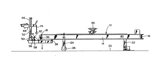
Figure 2 i8 a side elevational view of the assemblage
illustrated in Figure l;
Figure 3 is a perspective view o~ a portable pull tower
specially designed rOr use in con~unction with the support rack,
the near side support wheel o~ the pull tower being removed; ~
Figure 4 is a ~ragmentary enlarged vertical sectional
taken 9ubstantially upon the plane indicated by the sectlon line
4-4 o~ Figure 3;
Figure S i8 a rragmentary perspective view o~ the lower
portion o~ the support tower illustrated in Figure 3 and disclosing
the manner in which the pull tower is designed to be used in


. . ~

20~7~


conjunction wlth a floor mounted tra~k;
Figure 6 is a fragmentary enlarged vertical sectional
view illustrating the manner in which one of the carriages is
mounted from the periphery of the support rack for movement
thereabout;
.~ Figure 7 is a fragmentary enlarge vertical sectional view
taken substantially upon the plane indicated by the section line
7-7 of Figure 1 and with the corresponding end of the rack in a
lowered position and a portable pull tower positioned on one of the
carriages for loading onto and unloading from the corresponding
ramp end;
Figure 8 i8 a side elevational o~ the rack in an elevated
position and with a vehicle stationarily anchored in elevated
position relative to the rack through the utilization o~ rack
supported pinch weld clamps;
Figure 9 is an enlarged fragmentary vertical sectional
view taken substantially upon the plane indicated b~ the section
line 9-9 o~ Figure 8;
Figure 10 is an enlarged ~ragmentary perspective view
illustrating one marginal portion o~ the rack and a typiaal pinch
weld clamp supported there~rom;
Figure 11 i8 4 side elevational view o~ the rack in the
process o~ having a vehiale to be repaired loaded thereon to;
Figure 12 is a side elevational view of the rack with
gauge structure operatively associated therewith ~or use in gauging


,.:
.

.
' ,. ` , ' '~, ' ' ' ~ ,

--` 20117~


the relative positions of various vehicle componen~s.

DESCRIPTION OF THE PREFERRED EMBODIMENT
Referring now more specifically to the drawings the
numeral lo generally designates the vehicle repair support rack of
the instant invention. The rack lo comprises a structure which is
..
ovate in plan shape including a pair of longitudinally straight
opposite side portions 12 and 14 whose corresponding ends are
interconnected by front and rear semicircular portions 16 and 18.
The rack 10 is supported in elevated position from suitable
flooring 20 by a pair of depending front legs 22 from whose upper
ends the ~orward end of the rack 10 is mounted for oscillation
about a horizontal transverse axis and a pair of rear legs 24
between whose lower ends a flooring engagable roller 26 is
~ournaled and whose upper ends are swingably supported from the
rear half of the rack 10, suitable fluid cylinders 28 being
operatively connected between the rear half of the rack 10 and the
legs 24 whereby the rear end of the rack 10 may be raised and
lowered relative to the flooring 20, compare Figures 2 and 7.
The rack 10 includes an upper outer tubular raiL 30
extending thereabout as well as a lower inner tubular 32 extending
thereabout. The rails 30 and 32 deflne a peripheral guide track
and one or more carrlages referred to in general are provided and
include outer and lnner grooved guide wheels 36 and 38 rollingly
engaged with the rails 30 and 32. ~he carriages 34 are thereby
upported from the rack 10 from movement about the outer periphery


.:. , . , ~
~................ .. , ~ ~
' ' :
,
.'' .

2011~


thereof and each carriage 34 i~cludes a supp~rt table 40 supported
therefrom and extending outward from the corresponding peripheral
portion of the rack 10. Each support table has a transver~e anchor
rail 42 supported therefrom corresponding to a floor mounted pull
tower anchor rail and each support table 40 may support a portable
pull tower 44 therefrom constructed, generally, in accordance with
the pull tower disclosed in U.S. Patent No. 4,712,417.
The pull tower 44 is substantially identical to the pull
tower disclosed in U.S. Patent No. 4,712,417, but includes a tower
member 46 including a base portion 48 from which opposite side
support wheels 50 are journaled and an upper portion 52 pivotally
supported ~rom the base portion 48 for angular displacement
relative thereto about a vertical axis, as at 54, see Figure 4.
The base portion 48 includes a ~orwardly directed horizontal arm
56 including a support table engaging foot secured under the
~orward end of the arm 56 and a forwardly opening lower transverse
angle member portion 60 engagable behind and beneath the
corresponding anchor rail 42. Also, the lower end of the upper
portion 52 includes a ~orwardly and downwardly inclined brace 62
including a downwardly ~acing foot 64 on its lower end ~or swinging
movement over and engagement with the corresponding support table
40.
The upper portion 52 o~ the tower member 46 may o~ course
be angularly ad~usted about a vertical axis relative to the base
portion 48 by the pivot connection de~ined at 54. In addition,
the brace 62 swings relative to the base portion 48 with the upper


., , '

201~ 7~


portion 52 and the foot 64 slides over the support table 40 during
such adjustment. In this manner, the pull arm assembly 66 of the
pull tower 44 may be angularly adjusted about the vertical axis
defined by the pivot connection 54 relative to the base portion 48.
Each of the carriages 34 includes an apertured upper
horizontal flange portion 66, see Figure 6, disposed beneath the
upper plate 68 of the rack 10 and each opposite side portion 12 and
14 as well as at least the end portion 18 of the rack 10 includes
peripherally spaced apertures 70 formed in the upper plate 68
thereo~ with which the aperture in one of the flange portions 66
may be registered and lock pins 72 are removably downwardly
engagable through selected apertures 70 and a corresponding
apertured upper horizontal flange portion registered therewith to
thereby lock the associated carriages in selected positions about
the periphery of the rack 10.
Each of the portable pull towers 4~ includes a pull chain
74 operatively associated therewith and the unused end portion 76
o~ each pull chain 74 may be downwardly received through an
aperture 78 formed in the correaponding brace 62.
As shown in Figure 11, the rear end of the rack 10 may
be lowered toward the ~looring 20 and a ramp structure 80 may be
used when a vehicle 82 ls being loaded onto or unloaded ~rom the
ramp 10, the ~orward end of the ramp 10 being provided with a winch
assembly 84 for use in pulling the vehicle 82 up onto the ramp 10
over the ramp structure 80. In addition, when the ramp 10 has its
rear end lowered toward the flooring 20 in the manner illustrated

2 0 ~


in Figure 11 and ramp structure 80 is removed, a carriage 34 may
shifted to the rear end of the ramp 10 and utilized, in conjunction
with a smaller ramp structure 85 for the purpose of loading a
portable pull tower 44 onto the rack lo via the carriage 34 from
which the pull tower 44 ultimately will be supported.
Still further, each of the opposite side portions 12 and
14 of the rack 10 includes a hydraulic cylinder actuated scissors-
type jack 86 supported therefrom whereby the vehicle 82 loaded upon
the rack 10 may be elevated relative thereto. Also, each opposite
side portion and 12 and 14 of the rack 10 includes a pair of pinch
weld clamp assemblies referred to in general by the reference
numerals 88 guidingly supported therefrom for ad~ustable
positioning therealong. The pinch weld clamp assemblies each
include an outer side guiding and retaining flange 90 ~or
releasable clamped engagement with the outer marginal portion of
the upper plate 68 through the utilization of threaded fasteners.
In this manner, the pinch weld clamp assemblies 88 may be
releasably anchored in ad~usted positions along each of the
opposite side portions 12 and 14 Or the rack 10.
Each of the pinch weld clamp assemblies 88 includes a
pair Or pinch weld clamps 94 and 96 which are vertically ad~ustable
relative to the remainder Or the associated clamp assembly 88 and
each pinch weld clamp is basically similar to the pinch weld clamp
dlsclosed in U.S. Patent No. 4,718,266 and is therefore capable of
supporting the associated vehicle 82.
In operation, the vehicle 82 may be loaded onto the rack


'

,~ . : . .
! , . , `
'


.' .

2 0 ~


lo through utilization of the winch assembly 84 in the man~er
illustrated Figure 11. After the vehicle 82 has heen loaded, one
or more pull towers 44 may be also loaded upon the rack 10 through
the utilization o~ corresponding carriages 34 in the manner
illustrated in Figure 7. Thereafter, the jacks 86 may be utilized
to elevate the vehicle 82 to the position thereof illustrated in
Figure 8 and the pinch weld clamp assemblies 88 may be properly
positioned and clamped in position through the utilization the
threaded fastener~ 92 subsequent to the engagement of the pinch
weld clamps 94 and 96 with the pinch weld area 98 o~ the vehicle
82 in the manner illustrated in Figure 8. Thereafter, the pull
chains 74 o~ a plurality of pull towers 44 may be engaged with
selected portions o~ the vehicle 82 in order to exert straightening
pulls thereon. As herein before set ~orth, the upper portions 52
o~ the tower members 46 may be angularly adjusted, as desired and
the inclined braces 62 o~ the pull towers 44 are automatically
positioned with respect to the direction o~ the pulls to be exerted
by the chains 74 in order to brace the towers 44 against the pulls
exerted thereby, the pull towers 44 being previously positioned as
deslred by shifting o~ the carriages 34 to the desired positions
thereo~ and the locking o~ the carriages 34 in the sele¢ted
positions thereo~ through utilization o~ the lock pins 72.
As may be seen in Figure 12, a body component gauge
system lOO may be supported from the rack 10 and utilized to check
the relative positions of various selected areas of the vehicle 82.


,.~ ~. ~ . "....... ......... .
, . . .
:
:
.
.
.

.

20117~


The foregoing is considered as illustrative only of the
principles of the invention. Further, since numerous modifications
and changes will readily occur to those skilled in art, it is not
desired to limit the invention to the exact construction and
operation as shown and described and, accordingly, all suitable
modifications and equivalents may be resorted to, falling within
the scope of the invention.


11


t~
: ,
~ ` ' ~ , ,
.:

t.,

Representative Drawing
A single figure which represents the drawing illustrating the invention.
Administrative Status

For a clearer understanding of the status of the application/patent presented on this page, the site Disclaimer , as well as the definitions for Patent , Administrative Status , Maintenance Fee  and Payment History  should be consulted.

Administrative Status

Title Date
Forecasted Issue Date 1993-10-12
(22) Filed 1990-03-08
Examination Requested 1990-05-16
(41) Open to Public Inspection 1991-03-05
(45) Issued 1993-10-12
Deemed Expired 2002-03-08

Abandonment History

There is no abandonment history.

Payment History

Fee Type Anniversary Year Due Date Amount Paid Paid Date
Application Fee $0.00 1990-03-08
Maintenance Fee - Application - New Act 2 1992-03-09 $50.00 1992-03-06
Maintenance Fee - Application - New Act 3 1993-03-08 $50.00 1993-03-05
Maintenance Fee - Patent - New Act 4 1994-03-08 $50.00 1994-03-07
Maintenance Fee - Patent - New Act 5 1995-03-08 $75.00 1995-03-07
Maintenance Fee - Patent - New Act 6 1996-03-08 $75.00 1996-02-29
Maintenance Fee - Patent - New Act 7 1997-03-10 $75.00 1997-02-25
Maintenance Fee - Patent - New Act 8 1998-03-09 $75.00 1998-02-16
Maintenance Fee - Patent - New Act 9 1999-03-08 $75.00 1999-02-11
Maintenance Fee - Patent - New Act 10 2000-03-08 $100.00 2000-03-02
Owners on Record

Note: Records showing the ownership history in alphabetical order.

Current Owners on Record
HINSON, VIRGIL H.
Past Owners on Record
None
Past Owners that do not appear in the "Owners on Record" listing will appear in other documentation within the application.
Documents

To view selected files, please enter reCAPTCHA code :


To view images, click a link in the Document Description column. To download the documents, select one or more checkboxes in the first column and then click the "Download Selected in PDF format (Zip Archive)" or the "Download Selected as Single PDF" button.

List of published and non-published patent-specific documents on the CPD .

If you have any difficulty accessing content, you can call the Client Service Centre at 1-866-997-1936 or send them an e-mail at CIPO Client Service Centre.


Document
Description 
Date
(yyyy-mm-dd) 
Number of pages   Size of Image (KB) 
Cover Page 1994-07-09 1 22
Drawings 1994-07-09 4 115
Abstract 1994-07-09 1 42
Claims 1994-07-09 6 244
Description 1994-07-09 11 403
Representative Drawing 1999-07-19 1 8
Fees 1999-02-11 1 48
Fees 1998-02-16 1 53
Prosecution Correspondence 1990-05-16 1 41
Office Letter 1990-11-20 1 19
PCT Correspondence 1993-07-16 1 23
Fees 1997-02-25 1 41
Fees 1996-02-29 1 27
Fees 1995-03-07 1 27
Fees 1994-03-07 1 24
Fees 1993-03-05 1 23
Fees 1992-03-06 1 21