Language selection

Search

Patent 2011966 Summary

Third-party information liability

Some of the information on this Web page has been provided by external sources. The Government of Canada is not responsible for the accuracy, reliability or currency of the information supplied by external sources. Users wishing to rely upon this information should consult directly with the source of the information. Content provided by external sources is not subject to official languages, privacy and accessibility requirements.

Claims and Abstract availability

Any discrepancies in the text and image of the Claims and Abstract are due to differing posting times. Text of the Claims and Abstract are posted:

  • At the time the application is open to public inspection;
  • At the time of issue of the patent (grant).
(12) Patent: (11) CA 2011966
(54) English Title: FLUID MOTOR ROTOR ASSEMBLY
(54) French Title: ROTOR POUR MOTEUR HYDRAULIQUE
Status: Expired
Bibliographic Data
(52) Canadian Patent Classification (CPC):
  • 230/111
(51) International Patent Classification (IPC):
  • F04C 18/00 (2006.01)
  • F01C 1/00 (2006.01)
  • F01C 21/08 (2006.01)
(72) Inventors :
  • ALBERT, GREGORY P. (United States of America)
(73) Owners :
  • INGERSOLL-RAND COMPANY (United States of America)
(71) Applicants :
(74) Agent: NORTON ROSE FULBRIGHT CANADA LLP/S.E.N.C.R.L., S.R.L.
(74) Associate agent:
(45) Issued: 1998-12-01
(22) Filed Date: 1990-03-12
(41) Open to Public Inspection: 1990-09-17
Examination requested: 1997-02-07
Availability of licence: N/A
(25) Language of filing: English

Patent Cooperation Treaty (PCT): No

(30) Application Priority Data:
Application No. Country/Territory Date
325,568 United States of America 1989-03-17

Abstracts

English Abstract


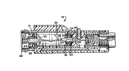
A rotor assembly for a fluid powered vane motor
has a cylindrical rotor body with front and rear
faces, front and rear shaft portions extending
axially from the respective faces, and radial slots
extending axially along the rotor body. Fixed to
the rear face of the rotor body is an end plate
which closes the slots at the rear face so as to
simplify assembly of the rotor body into the rotor
chamber by retaining the vanes in the slots. A
front spacer member on the front shaft portion
provides positive location of the rotor body with
respect to the shaft bearings, and also supports the
front end plate which radially circumscribes the
spacer member. In other respects, operation of the
vane motor containing this rotor assembly is typical
of air powered vane motors, in general.


French Abstract

Cette invention concerne un rotor de moteur à palettes entraîné par un fluide sous pression, qui a un corps cylindrique délimité par une face d'extrémité avant et une face d'extrémité arrière, qui portent, respectivement, un tourillon avant et un tourillon arrière dans le prolongement de l'axe longitudinal de l'ensemble, et comportant des rainures radiales dans le sens axial. La face d'extrémité arrière du rotor porte un flasque qui ferme les rainures radiales à ce bout du rotor afin de simplifier la mise en place de celui-ci dans le stator, les palettes étant ainsi retenues dans leurs rainures de fixation. Le tourillon avant porte une bague d'espacement qui assure le positionnement ferme du rotor entre les paliers du moteur en plus de porter le flasque avant du rotor. € d'autres égards, le fonctionnement du moteur à palettes équipé de ce rotor ne diffère guère de celui des moteurs pneumatiques à palettes en général.

Claims

Note: Claims are shown in the official language in which they were submitted.


The embodiments of the invention in which an exclusive
property or privilege is claimed are defined as follows:

1. A rotor assembly for a vane motor comprising: a
cylindrical rotor body having front and rear faces,
front and rear shaft portions extending axially from the
respective faces, front and rear bearings for rotatably
supporting said shaft portions, respectively, and radial
slots extending axially along the rotor body; a
plurality of radially slidable vanes disposed in said
radial slots; a rear end plate, having the same outside
diameter as that of said rotor body and substantially
the same as that of said rear bearing, fixed to the rear
face of said rotor body on said rear shaft so as to
rotate with said rotor body and to completely close the
slots at the rear face; a front spacer member positioned
on the front shaft portion so as to abut the front face
of the rotor body; and a front end plate radially
circumscribing the front spacer member so as to close
the slots at the front face while allowing relative
rotation between said spacer and said front end plate.

2. The rotor assembly of claim 1 wherein said front
spacer is integrally formed with said front shaft
portion.

3. A fluid vane motor comprising: a hollow cylinder
having fluid inlet and outlet ports; a rotor assembly
mounted for rotation within said cylinder about an axis
parallel to the axis of said cylinder, said rotor
assembly comprising: a rotor body having front and rear
faces, front and rear shaft portions extending axially
from the respective front and rear faces, front and rear
bearings for rotatably supporting said shaft portions,
respectively, and radial slots extending axially along
the rotor body; a plurality of radially slidable vanes
disposed in said radial slots; a rear end plate, having
the same outside diameter as that of said rotor body and


substantially the same as that of said rear bearing,
fixed to the rear face of said rotor body on said rear
shaft so as to rotate with said rotor body and to
completely close the slots at the rear face; a front
spacer member positioned on the front shaft portion so
as to abut the front face of the rotor body; and a front
end plate radially circumscribing the front spacer
member so as to close the slots at the front face while
allowing relative rotation between said spacer and said
front end plate.

4. The vane motor of claim 3 wherein said front
spacer is integrally formed with said front shaft
portion.

Description

Note: Descriptions are shown in the official language in which they were submitted.


201~966
Docket No. 0628-IR-TH

FLUID MOTOR ROTOR ASSEMBLY

BACKGROUND OF THE lNV~NllON

The present invention relates to fluid motors
and in particular to fluid vane motors having
sliding vanes.

Vane motors are well known and typically
05 include a tubular housing within which a rotor,
having radially slidable vanes, is arranged for
rotation about an axis offset from the axis of the
tubular housing. Openings through the
circumferential sides of the tubular housing or the
end plates of the housing define inlet and outlet
ports for the fluid motor. Positioning of the ports
determines the direction of rotation of the rotor.

The ends of the motor cylinder are closed by
end plates typically clamped against the end of the
cylinder. The end plates also typically support the
bearing assemblies for the rotor. The bearings are
conventionally located in cavities on the outside of
the end plates. Manufacture, assembly, disassembly,
and repair of conventional rotor assemblies is
difficult because of the complex construction. The
end plates and housing members must be disassembled
to gain access to the individual components.

SUMMARY OF THE INVENTION

It is therefore an ob~ect of the present
invention to provide a vane motor assembly having
fewer and simpler parts than conventional vane motor
constructions.


It is another object of the present invention to
provide a vane motor construction having easier manufacture,
assembly, disassembly, and repair.

It is another object of the present invention to
provide a rotor assembly having reliable take-up for axial
movement or tolerance.

It is a further object of the present invention to
reduce the number of parts for a vane motor.

In one aspect of the present invention, the above
objects are accomplished by providing a rotor assembly for a
vane motor and comprising a cylindrical rotor body having
front and rear faces, front and rear shaft portions
extending axially from the respective faces, front and rear
bearings for rotatably supporting the shaft portions,
respectively, and radial slots ~xtending axially along the
rotor body; a plurality of radially slidable vanes are
disposed in the radial slots. A rear end plate is also
provided and has the same outside diameter as that of the
rotor body and substantially the same as that of the rear
bearing. The rear end plate is fixed to the rear face of
the rotor body on the rear shaft so as to rotate with the
rotor body and to completely close the slots at the rear
face. A front spacer member is positioned on the front
shaft portion so as to abut the front face of the rotor
body. A front end plate radially circumscribes the front
spacer member so as to close the slots at the front face
while allowing relative rotation between the spacer and the
front end plate.

According to a further broad aspect of the present
invention, there is also provided a fluid vane motor which
comprises a hollow cylinder having fluid inlet and outlet
ports. A rotor assembly is mounted for rotation within the


-2-


cylinder about an axis parallel to the axis of the cylinder.
The rotor assembly comprises a rotor body having front and
rear faces, front and rear shaft portions extending axially
from the respective front and rear faces, front and rear
bearings for rotatably supporting the shaft portions,
respectively, and radial slots extending axially along the
rotor body. A plurality of radially slidable vanes are
disposed in the radial slots. A rear end plate, having the
same outside diameter as that of the rotor body and
substantially the same as that of the rear bearing, is fixed
to the rear face of the rotor body on the rear shaft so as
to rotate with the rotor body and to completely close the
slots at the rear face. A front spacer member is positioned
on the front shaft portion so as to abut the front face of
the rotor body. A front end plate radially circumscribes
the front spacer member so as to close the slots at the
front face while allowing relative rotation between the
spacer and the front end plate.

The foregoing and other aspects of the present
invention will become apparent from the following detailed
description of the invention when considered in conjunction
with the accompanying drawings. It is to be understood,
however, that the

2011966
Docket No. 0628-IR-TH


figures are not intended as a definition of the
invention but are for the purposes of illustration
only.

BRIEF DESCRIPTION OF THE DRAWINGS

Fig. 1 is a cross sectional side view
05 schematically illustrating an embodiment of the vane
motor assembly of the present invention; and

Fig. 2 is an exploded perspective view of the
vane motor assembly according to the invention.


DETAILED DESCRIPTION OF THE PREFERRED EMBODIMENT

In Figures 1 and 2, a fluid vane motor includes
a hollow cylinder 12 within which a rotor assembly,
shown generally by 14, is disposed. The rotor
assembly includes a cylindrical rotor body 16 having
front 18 and rear 20 faces. A front shaft portion
22 and a rear shaft portion 24 extend axially from
the respective front and rear faces. A plurality of
radial vane slots 28 extend axially along the outer
circumferential surface of the rotor body. The
slots are evenly spaced around the circumference.
Radial vanes 30 are slidably disposed in each radial
slot such that the length of each vane is
approximately equal to the length of the rotor
body. The length of the rotor body 16 is
approximately equal to the axial length of the
hollow cylinder 12.

Docket No. 0628-IR-TH 66

The rotor assembly 14 is mounted for rotation
within the hollow cylinder about an axis parallel to
and offset from the axis of the hollow cylinder. In
other words, the rotor assembly rotates in a
05 circular chamber eccentrically offset from the
center axis of the hollow cylinder member, as i8
conventional for vane fluid motors.

A rear end plate 34 having an annular shape is
fixed to the rear face 20 of the rotor body 16 so as
to close the vane slots at the rear face. In the
preferred embodiment, for example, the inner
diameter of the annular rear end plate 34 may be
such that the rear end plate is press fit onto the
rear shaft 24. Alternatively, the rear end plate
may be fixedly attached in a manner such as welding
or may be machined as an integral part of the rotor
body 16.

A front spacer member 38 has an annular
shape. The inner diameter is such that the spacer
member can be slid on the front shaft 22 so as to
abut the front face 18 of the rotor body 16. Since
the spacer 36 rotates with the rotor body 16, it
could alternatively be manufactured as a stepped
shoulder on the front shaft 22.

A front end plate 38 has a larger dimensioned
annular shape such that the inner diameter of the
front end plate will slide over the outer diameter
of the front spacer member 36 so as to allow
relative rotation of the spacer member 36~ rotor
member 16, and the end plate 38. The front

66
Docket No. 0628-IR-TH

end plate 38 radially circumscribes the front spacer
member 36 and abuts the front face 18 of the rotor
16 so as to close the slots 28 at the fror.t face.

A rear bearing 40, such as an antifriction
05 roller bearing, is positioned on the rear shaft 24
and is retained by means such as a press fit and a
retaining ring 42. A front bearing 44 i~ pressed
onto the front shaft 22. The front bearing is
axially positioned by the front spacer member 36.

The slidable vanes 30 are installed in the
vane slots 28 and the completed rotor assembly 14
can now be positioned in a rotor chamber. A forward
biasing means such as a wave spring 46 is placed
behind the rear bearing 40 to provide bias for
axially locating the rotor assembly. A clamp nut 48
is then tightened against the outer race of the
front bearing to axially secure the motor parts.

The serviceable parts of the rotor of the
present invention are easily accessible for
maintenance by simply unscrewing clamp nut 48 and
removing the rotor assembly 14. The part count
compared to a typical conventional vane motor
construction is less. Additionally, since the rotor
assembly has an integral rear plate 34, the vanes
will not slide axially when the rotor assembly 14 is
inserted or removed from the rotor chamber.

The rear end plate 34 is fixed to the rotor
body 16 and rotates with the rotor body. Thus the
rotor body is not confined on the rear end by a
stationary end plate and can therefore take up axial
movement or axial tolerances.

2Q~6
Docket No. 0628-IR-TH

Typical steps in assembling a rotor assembly
according to the present invention would be as
follows: a rear end plate 34 is pressed onto the
rear shaft 24 of the rotor body 16. The outer
05 diameter of the completed rotor i8 then ground to
tolerance. The rear bearing 40 i8 pres6ed onto the
rear shaft and a retaining ring 42 is positioned to
further retain the bearing. The front spacer member
36 is slid on the front shaft 22. The front end
plate 38 is slid over the outer diameter of the
front spacer 36 so as to circumscribe the front
spacer member. The front bearing 44 is pressed onto
the front shaft 22. The inner face of the front
bearing is ground flush to fit against the face of
the spacer member 36 so as to provide the proper
clearance between the rotating rotor and the
stationary end plate 38. Vanes are disposed in each
slot.

The rotor assembly 14 is then positioned in
the eccentric cylinder chamber to abut against a
spring washer 46 which provides bias for forward
axial bias of the rotor. The clamp nut 48 is then
tightened against the outer race of the front
bearing 44 to axially secure the motor parts. The
spacer member 36 is clamped tightly between the
bearing inner race and the front face 18 of the
rotor body. The inner race, spacer member and rotor
body thus all rotate as a unit. A power takeoff
spindle is located on the front shaft 22 to to
provide power takeoff for the rotational force
developed by the motor when energized.

20119fi~
Docket No 0628-IR-TH

While this invention has been illustrated and
described in accordance with a preferred embodiment
of a vane rotor in a handheld pneumatic tool, it is
recognized that variations and changes may be made
05 therein without departing from the invention as set
forth in the claims.

Representative Drawing
A single figure which represents the drawing illustrating the invention.
Administrative Status

For a clearer understanding of the status of the application/patent presented on this page, the site Disclaimer , as well as the definitions for Patent , Administrative Status , Maintenance Fee  and Payment History  should be consulted.

Administrative Status

Title Date
Forecasted Issue Date 1998-12-01
(22) Filed 1990-03-12
(41) Open to Public Inspection 1990-09-17
Examination Requested 1997-02-07
(45) Issued 1998-12-01
Expired 2010-03-12

Abandonment History

There is no abandonment history.

Payment History

Fee Type Anniversary Year Due Date Amount Paid Paid Date
Application Fee $0.00 1990-03-12
Registration of a document - section 124 $0.00 1990-09-12
Maintenance Fee - Application - New Act 2 1992-03-12 $100.00 1992-02-19
Maintenance Fee - Application - New Act 3 1993-03-12 $100.00 1993-02-25
Maintenance Fee - Application - New Act 4 1994-03-14 $100.00 1994-02-25
Maintenance Fee - Application - New Act 5 1995-03-13 $150.00 1995-02-27
Maintenance Fee - Application - New Act 6 1996-03-12 $150.00 1996-02-23
Maintenance Fee - Application - New Act 7 1997-03-12 $150.00 1997-02-27
Maintenance Fee - Application - New Act 8 1998-03-12 $150.00 1998-02-18
Final Fee $300.00 1998-07-21
Maintenance Fee - Patent - New Act 9 1999-03-12 $150.00 1999-02-24
Maintenance Fee - Patent - New Act 10 2000-03-13 $200.00 2000-02-18
Maintenance Fee - Patent - New Act 11 2001-03-12 $200.00 2001-02-20
Maintenance Fee - Patent - New Act 12 2002-03-12 $200.00 2002-02-21
Maintenance Fee - Patent - New Act 13 2003-03-12 $200.00 2003-02-24
Maintenance Fee - Patent - New Act 14 2004-03-12 $250.00 2004-02-20
Maintenance Fee - Patent - New Act 15 2005-03-14 $450.00 2005-02-21
Maintenance Fee - Patent - New Act 16 2006-03-13 $450.00 2006-02-17
Maintenance Fee - Patent - New Act 17 2007-03-12 $450.00 2007-02-19
Maintenance Fee - Patent - New Act 18 2008-03-12 $450.00 2008-02-18
Maintenance Fee - Patent - New Act 19 2009-03-12 $450.00 2009-02-17
Owners on Record

Note: Records showing the ownership history in alphabetical order.

Current Owners on Record
INGERSOLL-RAND COMPANY
Past Owners on Record
ALBERT, GREGORY P.
Past Owners that do not appear in the "Owners on Record" listing will appear in other documentation within the application.
Documents

To view selected files, please enter reCAPTCHA code :


To view images, click a link in the Document Description column. To download the documents, select one or more checkboxes in the first column and then click the "Download Selected in PDF format (Zip Archive)" or the "Download Selected as Single PDF" button.

List of published and non-published patent-specific documents on the CPD .

If you have any difficulty accessing content, you can call the Client Service Centre at 1-866-997-1936 or send them an e-mail at CIPO Client Service Centre.


Document
Description 
Date
(yyyy-mm-dd) 
Number of pages   Size of Image (KB) 
Representative Drawing 1998-11-06 1 13
Description 1997-12-24 8 268
Claims 1997-12-24 2 69
Cover Page 1998-11-06 1 56
Cover Page 1993-11-06 1 14
Abstract 1993-11-06 1 23
Claims 1993-11-06 2 64
Drawings 1993-11-06 2 49
Description 1993-11-06 7 227
Correspondence 1998-07-21 1 45
Prosecution Correspondence 1997-02-07 1 47
Prosecution Correspondence 1997-02-07 2 68
Fees 1996-02-23 1 55
Fees 1995-02-27 1 62
Fees 1994-02-25 1 45
Fees 1993-02-25 1 46
Fees 1992-02-19 1 51