Note: Descriptions are shown in the official language in which they were submitted.
2 0 1 2 0 ~ 5 -1- PATENT
~.E. 51,256
_
Phase Comparison Relaying System with
Single Channel Communications Link
Background of the Invention
Field of the Invention
This invention relates to protective relaying
systems for multiphase electric power distribution networks,
and particularly to such systems in which protective relays
at terminals at opposite ends of a protected line segment
exchange instantaneous current phase information over a
communications link for use in identifying faults in the
protected segment and for generating trip signals for
circuit breakers at each terminal which isolate the faulted
line segment.
Background Information
Electric power transmission lines are protected
against faults by protective relay systems which operate
circuit breakers to isolate the faulted segment of the
line. Such systems include a protective relay at each
terminal of the protected line segment which analyze line
currents and in some systems voltages to determine the
location of a fault and to trip the circuit breakers at the
terminals to isolate a fault determined to be between the
terminals.
In one type of protective relaying known as phase
comparison relaying, relays at the two ends of a protected
line segment generate for each phase a square wave signal
representative of an instantaneous comparison of the
magnitude of the current with a keying level indicative of a
20 1 2075
fault condition. These square wave signals for each phase
are transmitted over a communications link to the other
terminal where they are compared to local square wave
signals generated by instantaneous comparisons of the local
phase currents with other threshold signals. Coincidence of
the local and remotely generated square wave signals
indicate an internal fault and generate trip signals which
operate circuit breakers to isolate the protected line
segment. Examples of such phase comparison relaying systems
,0 are disclosed in U.S. patent nos. 3,986,079 and 4,053,940.
Typically, the remote square wave signals are
transmitted between the terminals at opposite ends of the
protected line segment over a two-way communications link by
modulating a carrier signal. While other modulating
techniques could be employed, U.S. patent no. 4,380,746
discloses a pulse period modulation technique which is used
with the pulse period demodulation technique disclosed in
U.S. patent no. 4,510,453 to provide a simple modulation-
demodulation scheme which meets the real time requirements
of phase comparison relaying.
Conyentionally, three separate two-way channels,
one for each phase, are used to exchange the square wave
information between terminals. Typically, a telephone modem
in which the modulated carrier is transmitted as tones is
used in the communication link.
Phase comparison relaying schemes may also
generate a direct transfer trip signal which is a direct
command to trip the remote circuit breaker independent of
the phase relation of the currents of the two terminals.
These signals may be generated for instance for maintenance
purposes, or to coordinate tripping of the circuit breaker
with circuit breakers in other protected line segments of
the distributing network.
20 1 2075
U.S. patent no. 4,464,697 discloses a technique
for transmitting this direct transfer trip signal over the
available communications channels by disconnecting the
square wave signals from the modulator and substituting a
separate tone generator unique to the direct trip signal.
While the current systems provide satisfactory
protective relaying, there is a need for a phase comparison
relaying system which requires fewer communications
channels.
Summary of the Invention
These and other needs are satisfied by the
invention which is directed to protective relay apparatus
which includes a protective relay at each terminal of a
protected line segment in a multiphase ac transmission line
and a single channel two-way communications link between the
protective relays. Each protective relay includes means
monitoring selected parameters in this transmission line
segment at the associated terminal for each phase and means
generating from the parameter signals square wave signals
2~ for each phase representative of predetermined conditions at
that terminal. A single, modulated carrier signal having
discrete levels of modulation for each instantaneous
combination of selected of the square wave signals for each
phase is generated for transmission over the single channel
of the two-way communications link to the other terminal.
Each protective relay also includes means for generating
remote square wave signals corresponding to the selected
square wave signals at the transmitting terminal from the
single modulated carrier signal received over the single
channel of the communications link. Each protective relay
compares for each phase the remote square wave signals
received from the other terminal with designated square wave
signals generated by that protective relay and generates
- 20 1 2075
,
trip signals for circuit breakers at the terminal in
response to predetermined comparisons.
In accordance with a particular embodiment
of the invention there is provided protective relay
apparatus for controlling circuit breakers at spaced
apart terminals in a protected line segment in a
multiphase ac transmission line, said apparatus
comprising:
a protective relay associated with each
terminali and
a single channel two-way communications
link between said protective relays, each protective
relay including:
means monitoring selected parameters in
said ac transmission line at the associated terminal
for each phase thereof;
means generating from said parameter
signals square wave signals for each phase
representative of predetermined conditions at the
associated terminal;
means generating a single, modulated
carrier signal having discrete levels of modulation
for each instantaneous combination of selected of
said square wave signals for each phase for
Z5 transmission over said single channel of said two-
way communications link to said other terminal;
means generating remote square wave
signals corresponding to the selected square wave
signals at the other terminal, from the single,
modulated carrier signal received over the single
channel of said communications link; and
means comparing for each phase the remote
square wave signals received from the other terminal
with designated ones of said square wave signals
generated at said terminal, and generating trip
_ - 4a - 20 1 2075
signals for said circuit breakers in response to
predetermined comparisons.
In accordance with a further particular
embodiment of the invention there is provided phase
comparison relaying apparatus for controlling
circuit breakers at spaced apart terminals in a
protected line segment in a multiphase ac
transmission line, said apparatus comprising:
a phase comparison relay associated with
each terminal; and
a single channel two-way communications
link between said phase comparison relays, each
phase comparison relay including:
means measuring the current in each phase
of said transmission line at the associated
terminal;
means generating a square wave signal for
each phase of said ac transmission line
representative of the instants when the measured
ZO current of that phase is above and when it is below
a selected keying level representative of a fault
condition;
means generating a single, multi-level
combined signal having a unique discrete level for
each instantaneous combination of square wave
signals;
means modulating a single carrier signal
with said single multi-level combined signal to
generate a single, modulated carrier signal;
means transmitting said single, modulated
carrier signal to the other terminal;
means demodulating said single, modulated
carrier signal received from the other station, to
generate a single, remote, multi-level combined
signal;
~ ,.._
v, , .~
- 4b- 2012075
means decoding said single, remote multi-
level combined signal to generate remote square wave
signals for each phase;
means for generating local square wave
security margin signals for each phase from said
measured currents; and
means for comparing said remote square
wave signal for each phase with said local square
wave security margin signals for that phase and
generating a circuit breaker trip signal when said
remote square wave signal and said local square wave
security margin signal have a predetermined phase
relation.
In a preferred embodiment of the
invention, a single modulated carrier signal is
generated by means which generates a combined signal
having discrete amplitude levels representative of
the instantaneous combination of the selected square
wave signals, and means for modulating a single
ZO carrier signal to generate the carrier signal having
the discrete levels of modulation for each
instantaneous discrete amplitude level of the
combined signal.
As applied to a phase comparison relaying
system the square wave signals transmitted to the
other terminal comprise signals generated by
comparing the phase current with a keying signal
selected to represent fault conditions at the
associated terminal. These signals which become the
remote square wave signals at the other terminal are
compared with local square wave signals generated
from comparisons of the local current signals with
security margin signals, with trip signals being
generated for designated phase comparisons between
the remote and local square wave signals.
,.~
- 4c- 20 ] 20~5
-
,..
As another feature of the invention,
square waves representing priority functions such as
a direct transfer trip, can be integrated into the
single modulated carrier signal as another discrete
level.
In a preferred embodiment of the
invention, the single multiple level combined signal
is generated by generating signals for each separate
square wave of different unit value and adding these
signals to generate the combined signal. The unit
values of each square wave signal are selected such
that a unique sum is produced for each unique
combination of the square waves. In the preferred
embodiment, the decoder means includes means for
20 1 2075
-
generating reference signals corresponding to each of the
unique sums. These reference signals are each compared with
the remote combined signal to generate one of a plurality of
intermediate signals for the combination of square wave
signals represented by the level of the remote combined
signal. Each of the intermediate signals which represents
the combination including a particular square wave signal is
applied to a logic gate which generates the remote square
wave signal.
Brief Description of the Drawings
A full understanding of the invention can be
gained from the following description of the preferred
embodiment when read in conjunction with the accompanying
drawings in which:
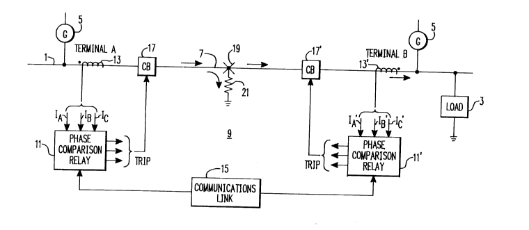
Figure 1 is a schematic diagram of an electric
power distribution system protected by a phase comparison
relaying system incorporating the present invention.
Figure 2 is a waveform diagram illustrating
signals generated by the protective relay system of Figure 1
in response to an external fault.
Figure 3 is a waveform diagram illustrating
operation of the protective relay of Figure 1 in response to
an internal fault.
Figure 4 is a truth table illustrating conditions
under which the protective relay of Figure 1 operating in
accordance with the scheme disclosed in Figures 2 and 3
generates a trip signal.
Figure 5 is a block diagram of a portion of the
protective relay in accordance with the invention which
generates the phase comparison signals.
Figure 6 is a block diagram of a portion of the
protective relay in accordance with the invention which
-~- 201 2075
-
prepares the square wave signals for transmission to the
other terminal.
Figure 7 is a schematic diagram of a circuit in
accordance with the invention suitable for generating a
combined signal for transmission to the other terminal.
Figure 8 is a truth table illustrating the
conditions for generating discrete levels of the combined
signal.
Figure 9 is a waveform diagram illustrating the
timing of signals generated by the circuit of Figure 7 in
response to fault conditions.
Figure 10 is a block diagram of the protective
relay in accordance with the invention which extracts remote
square wave signals from the modulated carrier signal.
Figure 11 is a schematic diagram of a suitable
circuit for extracting remote square wave signals from the
demodulated combined signal.
Figure 12 is a block diagram of a portion of the
phase comparison relay of the invention illustrating the
phase comparison and tripping signal generating circuits.
Description of the Preferred Embodiment
As shown in Figure 1, the invention is applied to
a three phase electric power distribution system 1 which
delivers to loads, such as the load 3, three phase
alternating current power generated by one or more
generators 5. At least one segment 7 of the electrical
power distribution system between the terminals A and B is
protected by a phase comparison relaying system 9 in
accordance with the invention.
The phase comparison relaying system 9 includes
phase comparison relays 11 which monitor the phase currents
20 1 2075
in the protective line segment 7 through current
transformers 13 and 13'. The phase comparison relays 11 and
11' compare information over a two-way communications link
15. In response to the identification of internal faults on
the protected line segment 7, the phase comparison relays 11
and 11' generate trip signals for one or all of the phases
of circuit breakers 17 and 17' which operate to isolate the
line segment 7.
The principle of operation of the phase comparison
relay system 9 can be understood from the examples shown in
Figure 2 through 4. Under normal conditions, that is no
internal faults in the protected line segment 7, current
will flow into terminal A and out of terminal B in supplying
power to the load 3. If there is an internal fault such as
at 19 in Figure 1, current will continue to flow into the
line segment 7 at terminal A but will reverse at terminal B
and flow into the fault if the fault offers a low resistance
path 21 to ground. If, however, the resistance to ground 21
of the fault 19 is high, current may continue to flow out of
terminal B, but at a much lower level than the current
flowing into terminal A.
The phase comparison relay schemes disclosed in
patent nos. 3,986,079 and 4,053,940 are able to detect
internal faults in the line segments 7 under both of these
conditions. As shown in Figures 2 and 3, each phase current
at each terminal is compared with a reference level, IKEy~
which is set at a level indicative of a fault. Each local
phase current is also compared with two other reference or
security margin signals of opposite polarity, one of which
Lp, is smaller in magnitude than IKEy~ and the other of
which is Ln is greater in magnitude. A square wave signal
ISw generated at each terminal is normally low but goes high
when the phase current exceeds IKEy. Additional square wave
- 201 2075
signals ISwp generated at each terminal are high as long as
the local phase current is more positive than Lp. In
addition, square wave signal ISwN are generated for each
phase which go high only when the local phase current is
more negative than LN.
Each terminal transmits over the communications
link 15 its local ISw square wave to the other terminal
where it is identified as the remote square wave RISw.
It will be noted from Figure 1 the signals
generated by the current transformers 13 at terminal A and
13' at terminal B have opposite polarity. Thus, in the case
of an external fault where the current continues to flow
into terminal A and out of terminal B for instance, the
corresponding phase currents at terminal A and B will be 180
degrees out of phase as shown in Figure 2. Each terminal
then looks for coincidence between the local ISwp and ISwN
signals, and the remote square wave signal RISw for each
phase. In the case of ISwp both the local signal ISwp and
the remote square wave signal RISw must be high
o simultaneously. On the other hand, the local signal ISwN
must be high when RISw is low in order to identify the
presence of an internal fault. As can be seen in Figure 2,
both phase currents are of sufficient magnitude to generate
the keying signals and the local security margin signals,
however, because the currents at the opposite ends of the
protected line segment are detected as being out of phase,
this is an indication that the current is flowing into one
terminal and out of the other terminal and, hence, the
detected fault is external to the protected line segment.
Figure 3 illustrates conditions for a large
internal fault with load current flowing into both
terminals. In this instance, it can be seen that a trip
signal is generated on the positive half cycle since both
-9- 20l 207~
-
the local signal ISwp and the remote square wave signal RISw
are high. A trip signal is also generated on the negative
half cycles when ISwN is high while the remote signal RISw
is low. In the example given, these conditions will exist
5 at both terminals and therefore both circuit breakers 17 and
17' will be tripped. Figure 4 illustrates a truth table for
the coincidence of the local square wave signals, ISwp and
ISwN with the remote square wave signal RISw required to
generate a trip signal.
In accordance with the present invention, the ISw
square wave offset keyed signals for each phase are
transmitted over the communications link 15 using one two-
way communication channel. Figure 5 illustrates the portion
of the phase comparison relays 11 and 11' for generating the
square wave signals at each terminal. As shown for the
phase comparison relay 11, the currents, IA, IB and IC
generated by the current transformer 13 are converted to
voltages ViA, ViB and Vic respectively in Current to Voltage
Converter 23. Signal conditioning such as low pass
filtering is applied to the current derived voltages in the
circuit 25 to produce conditioned voltage signals V'iA-
V iC These conditioned voltages are applied to Offset
Keyer and Squarer Circuits 27 along with the IKEy~ Lp, and
LN to produce the square wave signals ISw~ ISwp and ISwN for
each phase in accordance with the scheme described in
connection with Figures 2 through 4. Suitable Offset Keyer
and squarer circuits for accomplishing this function are
disclosed in patent no. 4,053,940.
As previously discussed, only the square wave
signals ISw for each phase are transmitted to the other
terminal. As shown in Figure 6, these signals ISw for each
phase are applied to a Multi-level Signal Generator 29,
together with-a direct transfer trip signal DTT, to generate
-lO- 20 1 2075
a combined square wave signal Sc which is applied to a
Level- To-Tone Converter 31. The combined signal Sc is used
in the Level-To-Tone Converter 31 to modulate a carrier
signal to produce a tone signal having a frequency related
to the magnitude of the combined signal. This tone signal
is passed through Output Conditioning and Drive Circuit 33
for application to the Communication Link 15 for
transmission to the other terminal.
Figure 7 is a schematic diagram of the Multi-Level
Signal Generator 29. An operational amplifier 35 is fed by
currents controlled by switches operated by the ISw
signals. For instance, switch A is closed when IASw is
high. Switches B and C are similarly controlled by IBSw and
ICsw respectively. The resistors RA, RB and Rc are selected
such that with switch A closed, a unit current i is
generated by a voltage source -V. RB and RC are selected
such that currents of 2i and 4i are generated when the
switches B and C are closed. Another switch D is controlled
by the direct transfer trip signal DTT. The resistor RDTT
is selected such that a current of lOi is generated when
switch D is closed. A complimentary switch D opens when
switch D is closed to assure that a current of lOi is
generated in response to a command for a direct transfer
trip. The operational amplifier 35 sums the currents
generated by the combinations of closures of the switches A,
B, C and D to generate a multi-level combined signal.
Figure 8 is a truth table for the Multi-level
Combined Signal Generator 29 of Figure 7. With no event,
all of the ISw signals and DTT low, a zero level combined
signal is generated. All eight possible combinations of the
three signals IASw~ IBSw and ICsw are represented by the
levels O through 7. A direct transfer trip (DTT) produces a
10 level combined signal. Levels 8 and 9 can be used for
201 2075
-
other selected priority functions. For instance, instead of
using DTT for all direct transfer trips, separate priority
signals could be used to indicate a direct transfer trip for
maintenance, another for a failure of a circuit breaker to
5 trip in another protective line segment, and so forth.
Information concerning other events or conditions could be
transmitted as a priority function on the single
communications channel if desired. Like DTT, these other
priority functions can be independent of the IAW signals as
O shown by the Xs in the Truth Table of Figure 8.
Figure 9 illustrates the timing of the wave forms
generated by the phase comparison relays of the invention in
response to the currents of phases A, B, and C following a
fault. As seen in the figure, each of the phase currents
exceeds the keying level, IKEy~ so that square waves ISw are
generated for each phase. While the three phase currents A,
B and C are 120 degrees apart, it can be seen that there is
some overlap in the ISw signals due to the greater magnitude
to the fault current in phase C. The combined signal Sc is
the sum of the signals IAsw, IBSW and ICSW The direct
transfer trip signal DTT is also included in Figure 9 as
well as its contribution to the combined signal Sc. As can
be seen, the combined signal Sc represents by its discrete
voltage levels the instantaneous combination of the
monitored events at the terminal.
The combined signal Sc generated at each terminal
is transmitted to the other terminal over the Communications
Link 15. Where the communications link comprises a
telephone channel, the combined signal Sc is converted to
various frequency tones. For instance, a base level of 1500
Hz can be used for the zero level with approximately 50 Hz
steps between levels so that at level lO, representing DTT,
the frequency is 2000 Hz as shown on the waveform Sc. This
-12- 201 2075
conversion can be implemented, for instance, by the pulse
period modulator of U.S. patent no. 4,380,746. As one
alternative, tones could be generated directly by a logic
controlled tone generator integrated circuit. This would
allow direct tone generation from the logic state as shown
by the truth table of Figure 8.
As shown in Figure 10, each phase comparison relay
11, 11', receives the tone signal transmitted from the other
terminal over the Communications Link 15 and passes it
through a Signal Conditioning and Noise Monitoring Circuit
37. The conditioned tone signal is converted back to a
remote multi-level combined voltage signal RSc in a tone to
level converter 39. The demodulator of U.S. patent no.
4,510,453 is suitable for this purpose. The multi-level
combined signal is then applied to the Level-To-Individual
Signal Decoder 41 for extraction of the remote square wave
signals RISw for each phase and the direct transfer trip
signal DTT.
The details of the Level-To-Individual Signal
Decoder 41 are illustrated in Figure 11. The recovered
level signal RSc which is similar to the combined signal Sc
shown in Figure 9 is applied to a comparator 43 associated
with each of the individual signals. The signal RSC is
compared in each of the comparators 43 with a reference
voltage corresponding to each of the respective individual
signals. Thus, the signal RSc is compared in the upper
comparator 37 with a 10 volt reference signal to generate
the DTT signal. If RSc exceeds the 10 volt reference
signal, DTT goes high. Similarly, immediate signals
corresponding to each of the combinations of ISw signals
listed in the truth table of Figure 8 go high when RSC
equals the reference voltage applied to the associated
comparator 43. The inverting input of each of the lower
-13- 201 2075
comparators in Figure 11 to which the reference voltage is
applied are tied to the outputs of each of the comparators
above by a diode 45 so that only the signal associated with
the highest level reference signal at any instant can go
5high. The intermediate signals representing the various
combinations of the square wave signals which include the
phase A signal are applied to an OR circuit 47 to generate
the recovered remote phase A square wave signal RIASw.
larly RIBSw and RICsw are recovered by applying the
0intermediate recovered level signals containing the
respective phase components to the OR circuits 49 and 51.
The remote square wave signals for each phase
received from the other terminal are applied to a Phase
Comparison Determinator 53, 55, and 57 for phases A, B and C
15respectively as shown in Figure 12. The remote square wave
signal for each phase is compared with the local positive
and negative square wave signal for that phase in the
associated Phase Comparison Determinator. Thus, RIASw is
p with IASWP and IAswN in the Phase Comparison
Determinator 53 in the manner explained in connection with
Figures 2 through 4. Suitable circuits for making these
comparisons are disclosed in U.S. patent no. 4,053,940.
Upon detection of an internal fault, the Phase Comparison
Determinators generate a respective phase trip signal. The
25phase trip signals for each phase are applied to a Tripping
Network and Logic Circuit 59, together with the direct
transfer trip signal DTT, to determine whether a single
phase or three-phase trip should be initiated in accordance
with known practice.
30While specific embodiments of the invention have
been described in detail, it will be appreciated by those
skilled in the art that various modifications and
alternatives to those details could be developed in light of
-14- 2012075
-
the overall teachings of the disclosure. Accordingly, the
particular arrangements disclosed are meant to be
illustrative only and not limiting as to the scope of the
invention which is to be given the full breadth of the
5 appended claims and any and all equivalents thereof.