Note: Descriptions are shown in the official language in which they were submitted.
18
13DV~8904
~YBRI~_~AMIN~R FLQW~A~L~L~ -
1 BA~ QUNP ~F ~H~ 2~CIQ~
3 Fi~l~ of thç ~hI~nti~n
The presen~ invent;on relat~s generally to a
nacelle $or housing an aircrat e~gine a~dO more
7 particularly, is co~cerned with a hybrid laminar flow
nacelle effective for producing low friction drag,
9 laminar flow at cruise operatio~ and separation-free
flow at of~-cruise (takeof or low speed~ operation of
ll an aircraft.
13 Pe~c~iL~ nf ~b~ t
In a ~ubsonic aircrat having an ~ternally
mounted engine~ for e~ample, a gas turbine engine
17 mounted below a wi~g by a pylonO aerod~namic drag due
to fre~stream airflow o~er the nacelle o~ the engine
l9 can typically represent appro~imately 4% of the total
engine thrust output. Any reduction in thi~
21 aerodynamic drag can result in a significant saving in
the amount of fuel consumed. Thus, a desired function
23 of an engine nacelle is to provide a lightweight
housiny for the aircraft engine which produces
25 relatively low aerodynamic drag~
13DV-a904
-- 2 --
1 The aero~ynamic dra~ due to a nacelle is
determined by ~he pressure distribu~ion and a
3 dimensionless friction coefficie~t C~ over th~ outer
surface of the nacelle over which the freestream air
5 flows durin~ aircraft ~lighta Reduced aerodynamic
drag exists where the surface pressure di~tribution
7 promotes a laminar boundary layer over the nacelle
outer sur~ace without any boundary layer æeparation
9 thereo~. The friction coefficient Cf, and thus
aerodynamic drag, have reduced values when a laminar
11 boundary layer esists. Where the boundary lay~r along
the nacelle outer surface transitions from laminar to
13 turbulent, the ~riction coefficient Cf, and thu~
aerodynamîc drag, have increased values, Accordi~gly,
15 it is d~sirable to proqide a nac~lle which promotes a
~urface pressure distribution effective for increasing
17 the extent of laminar boun~ary layer flow, reducing
the e~tent of tur~ulent flow and avoiding boundary
19 layer sepa~ation.
Previous experience has demonstrated that a
21 properly designed geometry o the outer surface o~ the
nacelle can provide a favorable pressure ~radlent over
23 an estended reyion of the nacelle, thus delaying the
transition from laminar to turbulent flow. The result
25 is a nacelle design with a lower friction or
a~rodynami~ drag and a co~se~uent reduction in fuel
27 bur~ of 1.0 to 1.5% during cruîse operation. ~n
esample of such nacelle ~esign is the natural laminar
29 flow nacelle (NLFN~ disclosed in U~ S. Pat. No.
4,799~633, issued to D. J. Lahti et al and assigned to
31 the assignee of the present invention. ~he NL~ can
result in a reduction of aerodynamic drag at cruise
33 operation of the aircraft of ap~ro~imately 50% when
compared to prior art nacelles~
~L2~
13DV-8g04
1 However, the NLFN with its emphasis o~ crui~e
performance ha~ a relati~ely sharp-lipped leadi~g edge
3 (as compared to a blunt-lipped leading edge of a
conventional nacelle) that is ina~equate for
5 o~f-cruise (takeoff or low speed, high
angle-of-attack3 operation of the aircraft.
7 Furthermore, during cruise operation of the aircraft,
the NLFN may i~cur incip;ent spillage drag and wave
g drag sooner than the conventional ~acelle ~that is, at
higher mass ~low ratios and lower freestream Mach
11 number respectively).
One conventional solution proposed for improvi~g
13 low speed operation of the NL~N by maintaini~g and
extending laminar flow is variable geometry or leading
15 edge ~ystems such as flaps or translating slats, as
recognized in the above-cited patent ~see column 8,
17 lines 49-55). While these appear to be viable
solutions, the weight and mechanical comple~ity of
19 such systems may cancel the benefits of the cruise
drag reduckion attributed to laminar flow produced by
21 the NLFN design. In addition, these solutions reguire
careful manufacturing to avoid ~teps and~or gaps in
23 the esternal eontour of the NhFN, when the system is
retracted for high speed operatio~, thag could resul~
25 i~ premature transition to tur~ulent flow indepen~e~t
of the pressure gradient or di~tribution.
27 Another conventional solution proposed for
maintainin~ a~d estendin~ laminar flow on wings and
29 nacelles has involved the use of active control
devices, as also recognized in the above-cited patent
31 (see column 2, lines 9-25)o An active ~ontrol device
requires an au~iliary source of energy to cooperate
33 with the surf ace for energizing or removing ~he
boundary layer for maintaininy laminar flow and
35 preventing boundary layer separation. For e~ample,
2~8
13DV-8904
1 boundary lay~r suc~ion or blowing ~lots or holes
dispose`d in th~ surface to be c:ontrolled are known in
3 thè art. The ~lot is conrlected to a pump by internal
ducting and is effectiv~ for reducing or preventing
5 turbulent ~low, and thereby maintaining lamirlar
boundary layer flow. Further~ boundary layer bleed
7 has been demonstrated æuccessfully irl maintaining
laminar f low orl airfoils gsee NASA Contractor :Report
9 165930 dated October 1982 entitled "Hybrid Laminar
Flow Control Study - Fi2lal P~epor~). Also0 boundary
11 layer bleed has been demon~trated theoretically to be
success~ul in mainta;ning attached f low on inlet lips
1~ at low speed,, high angle-of-attac:k conditions (see
AIAA-84-1399 dated June 1984 entitl~d ~Analytical
15 Study of Suction Boundary Layer Control for Subsonic:
V~Stol ~nlets~). Howe~er, the ad~itional weight and
17 energy required to power active con~rol devices
typically o~fsets advantages derived from the reduced
19 aerodynamic drag.
For high speed operation, l:he Nh~N is desi~ned
21 to a specific: operatillg point, or mass flow ratio
(~qFR), to provide the f avorable pressure gradien~
23 necessary to delay transition to turbulent ~low.
Decreasing the MFR below the design value can lead
25 initiall~r to premature transition to turbulent ~low,
thus losing the laminar flow drag advantage, a~d
27 eventually to earlier spillage dray than a
conventional nacelle. Also, since a relatively high
~9 ~Sach number near the ma~imum nacelle diameter is
required to keep the boundary layer laminar, wave drag
31 will become a problem at a lower freestream 2~ach
number than for a convenl;ional nacelle.
3~ Despite the significant advantages and
attainments attributed to the NLFN, it ætill
35 rapresents les~ than an optimal design for producing
2~
13DV-8904
1 low friction drag, laminar flow at cruise and
separation-free flow at off-cruise aircraft
3 operation. However, the conventional solutions
referred to above do not unequivocally suggest which
5 way one skilled in the art ~hould proceed toward
achievement of a more optimal Idesign. Consequently, a
7 need ~till remains for an alternative nacelle design
more nearly approaching optimum performance.
11
The present invention provides ~ hybrid laminar
13 flow nacelle (H~FN) de~igned to ~atisfy the
a~orementioned needs. The HL~N o~ the presen~
15 invention is effective for producing low friction
drag, laminar flow at cruise and separation-free ~low
17 at off-cruiæe (takeoff or low ~peed) opera~ion of an
air~raft. The HLFN design of the present in~ention
19 provides a ~ompromise nacelle which solves both the
low-speed and high-speed problems described above.
21 The HL~ is one that does not quite produce natural
laminar flow OA the esternal or outer ~urface at
23 cruise as does the abov~-cited ~LFN and one that
passively does not ~uite ~atisfy the low speed
25 requirements as does the conventional ~lunt-lipped
nacell~.
27 However, separation free flow at off ~ruise and
low aerodynamic drag laminar flow at cruise operation
29 of the aircraft are achieved in the HLFN by the
: combined effect of tailored geometry shaping of the
31 nacelle outer surface and use of active control
systems providi~g boundary layer bleed via air suction
33 elements, ~uch as porous walls, perforations or
slots. The geometry shape of the leading or forward
35 lip of the HLFN is blunter than the NLFN but sharper
.
2~
13DV-8904
1 than the conventional na~elleO Compared ~o the
conventional blunt-lipped na~elle which produces
3 turbulent flow at cruise opera~ion of the aircraft and
compared to the sharp-lipped NFLN whi~h produces
5 turbule~t flow and separation a~ off-cruise operation
of the aircraft, the round-lipped ~LF~ an~ boundary
7 layer bleed through ~he outer or e~ternal æurace of
the HLF~ produce laminar flow at cruise operation of
9 the aircraft and the rou~d-lipped HLFN a~d boundary
layer bleed through the inner or internal lip of the
11 HLF~ produce separation-free ~low at off-cruise (low
speed, high an~le-of-attack) operation of the aircraft.
13 ~ccor~i~gly, the present invention is dire~tsd
to a hybrid lami~ar flow nacelle for hous;ng an engine
15 of an aircraft. The ~L~N comprises: (a~ an outer
annular cowl having a leading lip and radially spaced
17 and a~ially extending annular outer and in~er ~orward
surface portions which mer~e at the leading lip; and
19 (b) a suction bleed system including a plurality of
air suction elements defined in the outer and inner
2~ forward surface portions a ially downstream from the
leadinq lip in the direction of airflow, suction
23 generating means, and a plurality of ducts
interconnecting the air suction elements and suctio~
25 generating means in flow communi~ation. Further, the
outer forward ~urface portion of the outer ~owl has a
27 geometry ~hape tailored to produce a substantially
uniform pressure in a boundary layer airflow along the
29 out~r sur~ace portion. Also, the suction generati~g
means is operable for applying suction selectively to
~1 the air ~uction element~ to cause bleed of the
boundary layer airflow through the air suction
33 elements at the outer surface of the cowl for
augmenting reduced friction drag laminar flow over the
3~ cowl at cruise operation o the aircraft and to cause
13D~-8904
1 bleed of t~e boundary layer air10w through ~he air
suction el~ment~ at the inner ~urace o the cowl for
3 preYenting ~eparation f low over th2 inner æur~ace of
t~e cowl at off-crui~e operation o~ the aircraft~
These and other ~eatures and ad~antagRs and
attainmen~s of ~he present in~ention will becom~
7 apparen~ to tho~e ~killed in the art upon a reading of
the following detailed description when taken in
9 conjunction with the drawings wherein there is shown
and described an illustrative emhodiment of the
11 invention.
13 ~
In the cour~e of the ~ollowi~g detailed
description~ reference will be made to the attached
17 drawings in which:
Fi~ a ~id~ elevational view, with portions
19 broken away and cross-sect;o~e~, of a turbofan engin~
moun~ed to a wing of an aircraft by a pylon an~
21 incorporating a prior art nacelle~
Fi~. 2 is a ~ragmentary longitudinal a2ial
23 sectional vi~w of a forward portion of the HLFN in
accordance with the present invention.
2S ~iq. 3 is a circle representing the e~ter~al
circumference of the HL~ at the location of the
27 forwardmost circumferential row of external air
suction ports to illustrate the circumferential
29 spacing of the e~ternal ports about the HLFN.
Fig. 4 is a eircle representing the internal
31 circumference of the HLFN at the location of the
internal air ~uction ports to illustrate the
33 circumferential spacing of the internal ports about
the HLFN~
Fig. 5A 5C are fragmentary longitudinal a~ial
L8
13D~-8 9 04
-- 8 --
1 se~tional view~ of upper orward portions of the
conventional nacelle, the ~LE~a and 'che ~IL~,
3 respectively.
Fig. 6A-6C: are graphs of the Mach number and
5 pressure gradient or ~listribution over the ~pper
~orward portions o th~ nacelles oiE ~i~s.. 5A-5C:. -
D~ATI.ED_~ES~IQN 0~ T~E I~NTIO~
In the following description, like reference
11 characters desi~nate likl~ or correspondi~g part~
throughout the ~everal viewsO Also in the following
13 description, it is to be understood that sut:h terms as
"for~ard", "rearward~ 3ft" ~ aright~ O "upwardly~ ~
lS ~downwardlya, and the 1~ kl3, are words of con~renience
and are not to be construed as limiting tQrms.
17
In Ge~ra1
19
Ref~rring now to the drawings, and parti~ularly
21 to ~ig. ;, a conventional gas turbofan engine 10 is
shown mounted by an aerodynamically ~haped pyloal 12
23 below and forwardly of a wing 14 o~ an aircraft (not
shown). An aircra~t with the engine and wing
25 arrangement shown in Fig. 1 is deæigned ~or subsorlic
operation.
27 The turbofan en~ine 10 includes a core engina 16
which produc:es thrust to propel the aircraiEt an~ a ~a~a
29 assembly 18 driven by the s:ore engine 16 to produce
additional thrust. Housin~ the engine 10 is an
31 annular nacell~ 20, such as the NL~N of the
above-cited patent, which includes an inner, or core,
33 cowl 22 surrounding the core ~3ngine 16 and an outer,
or fan, cowl 24 surrourlding the fan assembly 13. The
35 outer ~:owl 24 of the NLFN 20 also surrounds and is
l~Dt~-8904
_ g _
1 ~paced frorn a forward p~rtion of the in~er c:owl 22
thereof for deini~g an annular ~an discharge nozzle
3 26. The outer cowl 24 includes an inlet throa~ 28 for
receiving the engine airflow portion 30 of a
5 ~reestream airflow 32.
During aircraft speratiQn, the engine airflow 30
7 iæ accelerated by the an assembly 18 an~ is
discharged from the fan nozzle 26 over the imner cowl
g 22 of ~he NIJF~ 20 for generatin~ lthrust. The
freestream air ~low 32 10ws downstream over the outer
11 cowl 24 of the NLFN 20 and interact~ with or scrubs
the outer cowl 24 and produc:~s aerodyrlamic drag, a
13 ~ignificant ~ortiorl of which is frictional dray ac:tin~a
in a dire~tio~ opposite o that of the ~aoving ~ircraft..
A primary purpose of the present invention iæ to
provide modif ications to the nuter cowl 24 of the ~L~N
17 20 that are ef ~ective or reducing aerodynamic drag
due to ~reestream airf low 32 thereover duri~g cruise
19 opera~io~ o~ the aircraft and prevent separation at
off-cruis~ operation. However, inasmuch as engine
21 air~low 30 di~charged iErom the fan ~oæzle 26 primarily
~lows over the inner cowl 2~, the prof;le of the inner
23 cowl 22 of the NLFN 20 determined accordirlg to
conventional standards remains uncha~ged.
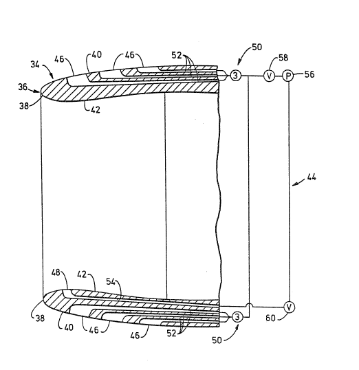
Hybri~ L~nar~aÇ~
27
Referring now to Fig. 2, thsre is illustrated
29 the ~orward portion of an outer aamular cowl 34 of a
hybrid laminar flow nacelle ~HL~N) 36 in accordance
31 with the present invention. The outer an~aular cowl 34
has a leading lip 38 and radially spaced and aa~ially
33 estending annular outer (or esternal) and inner (or
inter~al) forward surface portions 40, 42 which mer~e
35 at the leading lip 38 . The modif ications referred to
2~
13DY-8904
-- 10 -- .
1 above in~orpora~ed by the HL~ 36 that are efectaYe
for r~ducing aerodynamic ~rag durin~ crui~e operation
3 of the air~raft a~d preventing separation at
off-crui~e operation are a ~uction bleed ~y~tem 44 and
5 the geometry ~hape of the lea~iny lip 38 and the
annular outer forward ~urface portion 42 of the outer
7 cowl 34.
As seen in Fi~ 2, the suction bleed ~ystem 44
9 includes a plurality of air suction element~ 4S, 48
pr~ferably in the ~orm of ports, defined in respective
11 outer and i~ner forward ~urace portio~s 40, 42 of the
outer cowl 34 of the HLFN 36 and asially downstream
13 from it~ leading lip 38 i~ the direction of air~low.
The air ~uction port~ 46, 48 ~an take any suitable
15 form, such as porous wall ~ections, par~orations or
~lots. As seen in ~igs. 2 and 3, there is pre~erabl~
17 more than one row o~ outer ~or esternal~ ports 46 and
they are defi~ed in ~paced relatio~ to one another
19 about the complete circumferen~e o the outer cowl
34. One the other hand, as ~een ;~ ~igs. 2 an~ ~,
21 thare is preferably only o~e row of inner (or
internal~ ports 48 and they are de~ined i~ spaced
23 relation to one another only about a bottom arcuate
segment of the circum$eren~e of the outer cowl 34.
The suctio~ bleed ~y~tem q4 al~o includes a
suctio~ generatin~ m~ans 50 and a plurality o~ ducts
27 52, 54 e~tending throu~h the i~terior of the outer
cowl 34 between the outer and in~er surface p~rtions
29 40, 42 thereof and respecti~ely interconnecting the
outer and inner air suction ports 96, 48 and the
31 suction generati~g means 50 in flow communication. ~y
way of esample, a~ illustrated in ~ig. 2, the suctinn
33 generating means 50 can be composed of a pump 56 and a
13D~8904
1 pair of ~alves 58, 60 which respectively interconnect
the outer and inner ~uction por~ ducts 52, 54 with the
3 pump 56.
The valves 58 7 60 of th~ su~tion generating
S means 50 are operable for apply;ng air ~uction ~ia the
du~ts 52, 54 to selected ones of the air æuction ports
7 46, 48. For esample, a~ cruisa operation o the
aircraft, the ~alve 60 would be closed and the valve
9 58 would be opened to provide communication b~tween
one or more of the sets of outer air suction ports 46
11 to cause bleed o~ a portion of an ou~er boundary layer
airElow therethrough at th~ outer surface 40 of the
13 outer cowl 3~ ~or augmentlng reduced fri~tio~ drag
laminar ~low over the outer cowl. On the other ha~d0
15 at off-cruise operation of the aircrat, the ~alve 58
would be closed and the ~a~v~ 60 ~ould be opened to
17 provide communication between the inner air suction
ports 48 to cause bleed of a pnrtion of an inner
19 bou~dary layer airflow therethrough at the inner
surface ~2 of the outer cowl 34 for preventing
21 separation over the inner surface 42 of the outer cowl
34. Such bleeding of of a portion of the bou~dary
23 layer airflow as~ists in causing and maintaining the
boundary layer attachment to the ou~er and inn~r
25 surface portions 40, 42 of the airstream as it divides
and passes the leading lip 38 o~ the outer cowl 34 of
27 the HLFN 36.
Turning now to Figs. 5A-5C, it can be seen that
29 the desi~n of the HL~ 36 of the present invention i~
a compromise between the forward portion of the
~1 blunt-lip conventional nacelle 62 of Fig. 5A and the
forward portion of the sharp-lip NL~ 20 of Fig. 5B.
33 ~eferring to Figs. 6A-6C, and noti~g that Fig. 6C is
without æuction applied to the HLFN 36 of Fig. 5C, it
35 can be understood from the graphs of the Mach numbers
~3D~-8904
- 12
1 and pressure di~tri~utions of airflow progre~s~ng ~rom
the hilite of the nacell~s ~or orwardmost point on
3 the nacelles) in a downstream dire~tio~ therealong
that the HLFN 36 passively does ~ot quit prcduce
S natural lami~ar flow on its outer surface 40 at cruise
as does the NLFN 20 but is ~ubstantially bet~er ~han
7 the turbulent flow produced by the co~ventional
nacelle 62. Further, tha ~LF~ 36 passively dnes ~ot
9 quite ~atisy the off-cruise or low speed requirements
as does the blunt-lip conventio~al nacelle 62 but is
11 substantially better than the ~LF~ 20.
However, acceptable internal separation-~ree
13 flow aS of~-crui~e and esternal low aerod~amic dra~
laminar flow at cruise operation of the aircraft is
15 achieved in the ~LE~ 36 by the ~o~bined effect of
tailored geometry ~haping of the nacelle outer æurface
17 40 and use of æuction bleed system 44 to provide
selected outer a~d inner boundary layer bleed, as just
i9 described. As ~hown i~ FigO 6C, the outer forward
surface portion of the outer cowl 34 of the HLFN 36
21 has a qeometry shape tailored to produce a
substantially uni~orm pressure in a boundary layer
23 airflow along the cowl outer ~ur~ace 40. As seen i~
Figs. 5~-5C, the geometry shape of the leading or
25 forward lip 38 of the HLFN 36 is blunter than ~hat o~
the NL~ 20 but ~harp~r than that of the conve~tional
27 nacelle 62. Compared to the conventîonal blu~t-lip
nacelle 62 which produces turbulent flow a~ cruise
29 op~ration of the aircraft and compare~ to the
sharp-lip NFLN 20 which produces separated internal
31 flow at off-cru;se operation of the air~raftD the
round-lip HLFN 36 and boundary la~er bleed through the
33 outer or e~ternal surace 40 of the ~LF~ 36 ~roduce
laminar flow at crui~e operatiun of the aircraft and
35 the round-lîp HL~N 36 and bou~dary layer ble~d thro~gh
l~DV-8904
-- 13 --
1 the ~nner or interIlal ~urface 42 near the lip 38 of
the HLF~ 36 produc~ ~eparation-free internal flow at
3 o~cruise ~low ~peed, 31igh angle of-attack) c)peration
of tha ~ircraf~.
The advan~ages of the HI,~ 36 lie in the
combination o~ geometrie ~hape aT~d applîcation o
7 boundary layer bleed whi~h overcome~ the di~$i~ultil3s
of the NLFN 20 described earlierD The HL~ 36 i8 less
9 susceptible to early ~pillag~ drag at lower than
design MFPc (mass flow ratio~ because the geometrlc
11 shape o~ the lip i8 more like the blunt lip o~ a
conventional nacelle 62 than th~ sharp lip o~ the ~L~N
13 20. In addition, the rourl~ lip 38 pro~ides the ElI.EN
36 (without internal lip ~leed) wit!h ~ome
15 angle-of-attac:k capability at low speed wherea~ the
NLFN 20 (without variable ~eom~try) has no
17 capability. The boundary layer bleed on the external
sur~ace of the HLFN 36 not only pro~ides laminax ~low
19 at the design point, but prevents premature tra~sition
at lower than the tlesign MFR. The HLF~a 36 1: leed
21 æystem is desig~ed to overcome the slight adverse
pressure gradient present at the s~esign ~ , but
23 additional bleed car~ be applied if the ~aradient
becomes moxe æevere. Fi~ally, since the HL~ ~6 does
25 not require as hîgh a Mach number at the maximum
diameter, wave drag is likely to be less of a problem
27 than f or the NLEN 20 .
The disadvantages of the HhFN 36 are the need
29 for an au~:iliary power source to drive the bleed pump
56 which increases the parasitic demands sf the engine
31 and the add~ tlonal weight of the bleed system (pump,
duc:ts ~ et~) . The power demand can be kept to a
33 minimum through adjustments to the outer cowl contour
to minimize the e~terlt and degree of the ad~3rse
35 pressure ~radient and thxough judicious determination
. 13D~-8904
1 of the location and este~t of the suction region~ over
the fan cowl. T~e additional w~ight is characteristic
3 of both the HLF~ 36 and ~N 20, requiring
optimization.
S It is thought that the present inv2ntion a~d
many of its attendant advantages will be understood
7 from the fore~oing description and it w;ll be apparent
that ~arious changes may be made in the for~,
9 construction and arra~gement of the parts therenf
withou~ departing from the spirit and ~cope o~ the
11 invention or sacri~icing all of its material
advantages, the forms herei~before described being
13 merely preferred or e~emplary embodiments thereo.