Note: Descriptions are shown in the official language in which they were submitted.
201 2453
The present invention relates to a push switch, more
specifically, to a self-resetting push switch that can be
assembled easily and efficiently.
Conventional self-resetting push switches are shown in,
for example, Denpa Shinbun "Special Edition on Switches"
(issued on March 24, 1980), and "The Latest Audio
Encyclopedia" (published by Radio Gijutsusha).
The prior arts shown in these publications are switches
which are operated vertically relative to their main bodies.
Among switches having this arrangement, the single
acting type and the interlocking type, in which a plurality
of switches form a block structure, are well-known.
A switch of either of the types comprises movable
contacts moving as a switch rod moves, and a housing holding
the switch rod and accommodating stationary contact members
as well as a spring for limiting the range of movement and
for returning the switch rod.
In the above-described prior art, it has recently been
regarded as of importance to reduce the size and weight of
switches in order to make them more applicable to actual
mounting or assembly by the users.
- 1 -
.
20 1 2453
Therefore, the manufacturers have improved the level of
reliability and operability. Consequently, however, the
total number of the component parts has increased, and the
efficiency of assembly by the manufacturers is lowered. When
S low efficiency of assembly is combined with increase in
material and labor cost, the prices of products may increase,
and this may weaken the competitive power of the manufactures
in the international market.
The present invention provides a self-resetting push
switch whose assembly can dispense with screws that may
increase the total number of component parts or a soldering
process that may increase the total number of assembly
processes, and whose various component parts are inserted
into others utilizing the resilience of the materials they
are formed of, thereby enabling easier and more
: . ,
DAN, DAN & DAN
201Z453
efficient assembly without degrading reliability and operability.
A self-resetting push switch according to the present invention
comprises: a closed-end insulating housing having two respective
pairs of first and second opposing inner wall surfaces;
first grooves formed on the first pair of the opposing inner wall
surfaces; a second groove formed on at least one of the second
pair of the opposing inner wall surfaces, the second groove
having a projection formed therein; a first stationary contact
piece inserted in one of the first grooves; first and second
movable contact pieces, the first movable contact piece being
capable of coming into sliding contact with the first stationary
contact piece; an operation rod having a sliding sleeve integral
therewith, the first and second movable contact pieces projecting
outwardly from the sliding sleeve, the sliding sleeve having at
least one engagement piece engageable with the projection within
the second groove; a spring interposed between the bottom surface
of the housing and the lower surface of the sliding sleeve, the
spring always urging the operation rod in such a manner that part
of the operation rod always projects from the housing; and a pair
of conductive and resilient fixing pieces having a second
stationary contact piece capable of coming into sliding contact
with the second movable contact piece, the conductive and
resilient fixing pieces being disposed in such a manner as to
bridge two opposing positions on the upper portion of the
DAN, DAN & DAN
2012453
housing.
,
The self-resetting push switch according to the present invention
operates in the following manner. Normally, the movable contact
pieces are kept in contact with the corresponding stationary
contact pieces. When the operation rod is pushed down against
the force of the spring, one of the movable contact pieces is
released from its contact with the associated stationary contact
piece,thereby disconnecting the electrical connection between the
two stationary contact pieces. Thereafter, when the force
applied to the operation rod to push it down is released, the
force of the spring causes the movable contact pieces and the
operation rod to ascend to return to their normal position.
Following this action, the two stationary contact pieces are
electrically connected with each other through the movable
contact pieces, and the circuit is closed.
One of the two stationary contact pieces, more specifically,
the second stationary contact piece, is formed as being
integral with the pair of conductive and resilient fixing pieces.
Therefore, grounding of e.g. the body of a vehicle can be
achieved through the conductive and resilient fixing pieces, and
the contact piece need not be fixed to the body by screws.
~ 201 2453
The accompanying drawings illustrate one embodiment of
the present invention, in which:
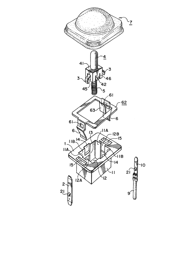
Fig. 1 is an exploded perspective view of a self-
resetting push switch;
Fig. 2 is an enlarged vertical section of a waterproof
cap:
Fig. 3 is an enlarged vertical section of an assembly in
which movable contact pieces and a spring are mounted on a
sliding sleeve;
Fig. 4 is an enlarged vertical section of another
assembly in which a stationary contact piece and a pair of
conductive and resilient fixing pieces are mounted on a
housing;
Fig. 5 is an enlarged and exploded vertical section of
the assembly shown in Fig. 4;
Fig. 6 is an exploded view of a member including the
conductive and resilient fixing pieces;
Fig. 7 is a plan view of the push switch as a finished
product;
201 2453
Fig. 8 is a left side view of the push switch shown in
Fig. 7;
Fig. 9 is an enlarged section taken along the line A-A
shown in Fig. 7;
Fig. 10 is an enlarged section taken along the line B-B
shown in Fig. 7;
Fig. 11 is an enlarged section taken along the line C-C
shown in Fig. 8; and
; Fig. 12 is an enlarged section showing a state different
from that shown in Fig. 11.
One embodiment of the present invention will now be
described with reference to the drawings.
A push switch according to one embodiment of the present
invention mainly comprises, as shown in Fig. 1, a housing 11,
a first stationary contact piece 2, a movable contact member
including movable contact pieces 3, operation rod 4,
a spring 5,
.
.
~ DAN, DAN & DAN
Z012453
a frame 62 including a second stationary contact piece 63, and a
waterproof cap 7.
The housing 11 has an insulating base 1 which is formed by
molding plastic material, as shown in Figs. 1, 5 and 9.
The housing 11 has a closed-end angular cylindrical
configuration with a cavity 12 defined by two pairs of opposing
inner wall surfaces 11A and 11B. One pair of opposing inner wall
surfaces 11A have grooves 12A and 12B formed thereon. Grooves 14
are formed on the other pair of opposing inner wall surfaces11B,
and they have projections 13 formed at an intermediate height of
the grooves 14, each projection 13 having a sloped surface and a
horizontal surface. A pair of engagement hoies 15 are formed
through upper portions of the housing 11.
The first stationary contact piece 2 has an engagement pawl 21
engageable with an engagement stepped portion 12a of the groove
12A formed on the inner wall surface 11A of the housing 11. The
stationary contact piece 2 is inserted into the housing 11 by
bringing the pawl 21 into engagement with the portion 12a, as
shown in Figs. 4 and 11. A lower portion of the contact piece 2
allows a lead to be extended therefrom.
One of the movable contact pieces 3 is capable of coming into
sliding contact with the first stationary contact piece 2, and
D~N, DAN & DAN
Z012453
the other with the second stationary contact piece 63. The
movable contact pieces 3 are formed of a conductive and elastic
material, and they have a flattened and inverted V-shape. The
operation rod 4 has a sliding sleeve 41 formed integrally with a
a lower portion of the rod 4 and provided with a projection end
44. The movable contact pieces 3 are disposed in such a manner
as to project outwardly through notches 45 of the sleeve 41, as
shown in Figs. 1, 3 and 11. A pair of resilient engagement
pieces 42 are formed on the sliding sleeve 41, as shown in Figs.
1, 9, 10 and 11. The engagement pieces 42respectively have one
each of sloped surfaces and horizontal surfaces, and they are
engageable with the projections 13 within the grooves 14.
Slits 46 are formed to allow the engagement pieces 42 to
exhibit resilience.
Part of the operation rod 4 is always projected from the cavity
12 by a spring 1S interposed between the bottom 11C of the
housing 11 and the lower surface of the sliding sleeve 41, as
shown in Figs.1 and 3. The sliding sleeve 41 is slidable inside
the cavity 12 alonq the grooves 14, and the resilient engagement
pieces 42 can be pushed down below the projections 13, as
shown in Figs. 9, 10 and 11.
Although two resilient engagement pieces 42 are provided in the
illustrated embodiment, only one resilient engagement piece may
DAN, DAN ~ DAN
201Z453
be provided.
As shown in Figs. 1, 4, 5 and 6, a pair of conductive and
resilient fixing pieces 6 is formed on two opposite sides of the
frame 62, and they have a pair of engagement pawls 61 engageable
with the engagement holes 15. The second stationary contact
piece 63 has a length corresponding to about one half of the
depth of the cavity 12. As shown in Figs. 9 and 11, the
conductive and resilient fixing pieces 6 are mounted on the
housing 11 with their engagement pawls 61 kept in engagement with
the holes 15, while the stationary contact piece 63 is kept in
engagement with the groove 12B formed in the associated inner
wall surface 11A of the housing 11.
The flexible waterproof cap 7 shown in Figs. 1 and 2 is disposed
on the outer edge of the insulating base 1, as shown in Figs. 9
and 11 in case such is required depending on the location of use.
When the cap 7 is employed, the switch serves as a waterproof
self-resetting push switch.
If the stationary contact piece 2 is substituted by a known tab
terminal 10 having a lead 9, shown in Fig. 1, its connection with
an external circuit is facilitated.
The housing 11 and the operation rod 4 are formed of insulating
DAN, DAN & DAN
201245~
material such as synthetic resin that can be poured into a mold.
The stationary contact piece 2, the movable contact pieces 3, the
conductive and resilient fixing pieces 6, the spring 5, and the
stationary contact piece 63 are formed of metal material. In
particular, the stationary contact piece 2 and the movable
contact piece 3 are formed of elastic and highly conductive
materials, such as phosphor bronze.
The waterproof cap 7 is formed of soft rubber.
'
The self-resetting push switch according to the present invention
comprises the above-described component parts.
The switch is assembled in the following manner:
First, as shown in Figs. 1, 3 and 4, the movable contact member
is inserted into the sliding sleeve 41 of the operation rod 4 in
,.
such a manner that the movable contact pieces 3 project outwardly
through the notches 45 of the sleeve 41. The projecting end 44
of the sleeve 41 is pushed through a mounting hole of the movable
contact member.
Thereafter, the projecting end 44 extending through the mounting
hole is inserted into a first end of the spring 5 to be fixed
thereon.
1 0
~ DAN, DAN & DAN
20124S3
The thus obtained assembly is inserted into the cavity 12 of the
housing 11 shown in Fig. 5 while the assembly is positioned in
such a manner that the resilient engagement pieces 42, which
serve to prevent the sliding sleeve 41 from slipping-off, are
received in the grooves 14, as shown in Fig. 9 During this
insertion, the projecting portions of the movable contact pieces
3 are pressed inward against their resilience to be retracted.
When the sloped surfaces of the resilient slip-prevention
engagement pieces 42 slide on the sloped surfaces of the
projections 13 at intermediate portions of the grooves 14, the
resilient engagement pieces 42 retract inwardly by virtue of the
formation of the slits 46. When the resilient slip-prevention
engagement pieces 42 have cleared the projections 13, the
horizontal surfaces of the projections 42 contact the horizontal
surfaces of the projections 13. In this condition, the sliding
sleeve 41 is prevented from slipping off the cavity 12, as shown
in Fig. 9.
During this insertion, a projecting portion 12E at the center of
the bottom 11C in the cavity 12 is inserted into a second end of
the spring 5.
The stationary contact piece 2 shown in Fig. 1 is inserted from
an insertion opening 12b of the housing 11 into the groove 12A.
~ D~N, DAN & DAN
20~245~
During this insertion, after the engagement pawl 21 has passed
the insertion opening 12b, it recovers its original position to
engage with the inner surface at the engagement stepped portion
12a, as shown in Fig. 4. By virtue of this engagement, the
stationary contact piece 2 is mounted thereon not to be slipped
off.
Thereafter, while the stationary contact piece 63 is brought into
engagement with the groove 12B, the engagement pawls 61 of the
conducive and resilient fixing pieces 6 are brought into
engagement with the engagement holes 15. When the pawls 61 are
pressed against the lower surface of the insulating base 1, as
shown in Fig. 4, the frame 62 including the conductive and
resilient fixing pieces 6 is fixed to the insulating base 1.
The push switch, assembled in this way without using any fixing
means such as screws or soldering, is used after assuming the
state shown in Figs. 9 and 10, in which the housing 11 is
inserted into a housing mounting hole 31 formed through a
mounting plate 30 against the resilience of the conductive and
resilient fixing pieces 6, and it is then held in place utilizing
the resilience of the pieces 6.
Since the lower surface of the insulating base 1 defines a
stepped portion 1A, a gap is formed between this lower surface
D.~N, ~AN & DA~
Z012453
and the upper surface of the mounting plate 30. The waterproof
cap 7 may be fitted around the insulating base 1 with the outer
edge of the cap 7 filling the gap. If the cap 7 is used, the
self-resetting push switch is waterproof.
The self-resetting push switch according to the present invention
is a normal closed switch. In its normal state shown in Fig. 11,
the movable contact pieces 3 are kept in contact with the
stationary contact piece 2 and the stationary contact piece 63.
If the push switch is to be used as a door switch of a vehicle,
the negative terminal of the battery is connected to the chassis
serving as the housing mounting plate 30, while the positive
terminal of the battery is connected through the associated door
lamp to the stationary contact piece 2. With this arrangement,
when the door is opened, the door lamp is turned on. When the
door is closed, the door lamp is turned off because, as shown in
Fig. 12, the operation rod 4 is pushed into the cavity 12 of the
housing 11 against the force of the spring 5, causing the movable
contact piece 3 to be released from its contact with the
stationary contact piece 63 which extends through about one half
of the depth of the cavity 12.
In the above described example, the first stationary contact
piece 2 may be substituted by the tab terminal 10 (shown in Fig.
' ' , - , '
.
.
DAN, DAN & DAN
20~2453
1) provided with a lead 9.
The present invention having the above-described arrangement
provides the following advantages.
When a self-resetting push switch as defined in the appended
claim 1 is to be assembled or when it is to be actually mounted
onto, e.g., the body of a vehicle, the switch can be assembled or
mounted by fitting its various component parts into others or by
fitting it into a suitable portion, without requiring any fixing
means such as screws or soldering. Such fitting is advantageous
in that the total number of the component parts as well as the
total number of assembly or mounting processes can be reduced
thereby enabling reduction in production cost. Furthermore,
since the assembly or mounting can be automated, mass production
is possible. In addition, after the push switch has been
assembled, the spring 5 and the operation rod 4 are held within
the housing 11 by the resilient engagement pieces 42, and the
operation rod 4 is prevented from slipping off. This means that
the conductive and resilient fixing pieces 6 can be ass~embled
onto the insulating base 1 at a separate location, thereby making
it possible to divide the entire assembly processes. In this
case, assembly work can be performed in narrow places, and it is
possible to avoid contamination of the switch contact portions by
substances, such as dust, which might hinder electrical contact.
14
D~N, DAN & D~N
2012453
Another noteworthy feature of the present invention is that the
second stationary contact piece 63, among said two stationary
contacts, is formed to be integral with the conductive and
resilient fixing pieces 6. This enables grounding of e.g. the
body of the vehicle to be achieved through the conductive and
resilient fixing pieces 6, without requiring the contact piece 63
to be fixed to the body by screws.
.~
If the push switch includes a flexible waterproof cap 7 disposed
around the outer edge of the housing 11, the push switch serves
as a waterproof self-resetting push switch.
If the stationary contact piece 2 is substituted by a tab
terminal 10 having a lead 9, this facilitates its connection with
an external circuit.