Note: Descriptions are shown in the official language in which they were submitted.
CO~ VEH~~TaE wI'~H EE3QD~E%.~ ~0~' pI~~F~7Rhi
~~6~~1.~c~ the ~n~~smtion
The pr~s~nt inv~nt,ion re3.ates t~ military combat vehicles
and more particularly to ~ni~.~.taa~ v~hiclss having a plurality of
weapons car sensors 3ocat~d on the booms or arms ~upportst~ on '~ha
main carriage of th~ v~hicle. rn the even gsaatar particularity
the present invention relates to oombat vehicles wha.rain a
plura~.x.ty of eactsnded booms are utilizod to c~~ploy woapons anr~
s~nsors at ~lwations and aaimuths relative to the main game
while in a combat ~odl~.
o ,c~acound c! txxs ~,~~~ t n
P~il3,tary co~abat vehio7l~es ~r.ith manned and un~aanned coaabat
plat~o~ms ~rhich can be elevated have !seen suggested in they early
seventies in s~v~ral variants. Ec~. ~~:~-~a~n 22 05 926, 235?505,
29542?$, which show light vehicl~ss without armor, with raiseabla
unmanned platforans o~° tJp-1~S 3?s?635, DE-OSen 2622995 anal 35924244
a,s well as 1~E~P~ 312m~3a which shows ~w arnaorcd c~c~mbat vehicle
with a raieabla ta~xmanned combat platform plus an additional
rais~abls get of visionias. these three basi~a types which have
evoJ.ved during the last. few years have since been further
dc~velope~ arid rei'sa~ed. X11 0~ these are based on the following
military reeoe~nition: "with hc~i~ht ~n~ ga~in~ de~at~h'e.
Fur°~hera~ore, ths~y ~ffer the possibility to ~coep the vehicle
and
cr~w under crwer an~1 e~p~se only the weapons and observation
system to direct enemy fire.
~:~..~~
The main purpess~ caf v~hic:laas with raiseable combat platfo.rra~s
is seen in their deployment against mas~iv~ly attacking tanks and
their possible helicopter-escoms. fox this x~aason armored, and
preferably cha~.l~ equipped, vehicles are b~aing progc~sed for
oarr~.ers ref carnbat platforms and the~,x elevatinr~ mechanisms. For
instance, He:mao orb, "~attendibl~a anti-tank and observeation
pla:tform,'~ in "~zznada International'° 6/~,98~ au~ggegts to re~-equip
combat tanks or similar slated for retirement, for this purpose.
It is the o;~ject of the present invention to prov3r~e a
combat vehicle having twa elevating mechan3.sms and combat
platforms which can be deployed indmp~ndently from each other and
are thus aapalala of combat against s~RVeral aerial and ground
ta~cgets simultaneously in di~Pferent directions and at different
ranges from partially or fully Govar~:d positions wherein the
vehicle itself remains out of the l~,nn of fir~ of the ~targ~te
Another object of the present invention is to prcwide a plurali'~y
of elevated mechanisms W~.ti~ oombat platforms whereby multiplo
ax~m~amerat.s may allow morn flexible combined or separate deployment
of available weapons aga~.nst the enemy. Yet another object. of
the invention is to provide conventional Fighting v~ehioles with
the ~abi~.ity to be upgraded and mG~dern$zed ut$liz$ng a~n mrmamant
set oompxising a movable boon sad a combat platfor~n9
These and other' ob j acts are advantagsca~asly achieved ire the
present ir~venti,or: thrbuc~h the use of two independently
maneuverable cr:mbat platforms at the upper end of twa separat~
omni-directionally taovable clcvating mechanisms, which are dined
at their lower end to a vehicle, as with universal-type gear
ring. The uac '~h~ plurality of combat platforms provides the
ac~vantag~a of doubling the amount of ar~aamcnt~ which may be
deplayed s.imul'~ariaously. It should be understood that the
freedom of mvve~nent of the twa independently operated combat
pl~ti~forms and elevated mechanisms allows for more effective
combined or sep~arat~ daploymsn~t of the armament and equipment
carried on the Combat platforms against ground to aerial targets
in the same or different directions a.nd distances.
rn t~i~ia way advantages accrue inasmuch as cc~nv~ntional
combat vehicle~sr especially armored ones, can now be rc-equipped,
without any problems and in a very short time, with modern
elevating ac~mbat platforms which in turn enables them to carry
accurate fire pow~x~ deep into ~nevmy territory and thus
sub~staritially increase their dei'ens~,va capability, without
diminish~.ng tPa~ir ability for aonv~nt.~.onal deployment.
ru~thermoxc, ~t~i~ armam~n4 ~~t is aomparativaly low cost thus
tla~lping to promotd the mi~.itary and commercial requirement f'or
supplying ~h~ def~nss farces with r~a~aonak~ly pric~sl, ~impl~ to
operate but h~~,c~hly affective defens~iva w~aponss systems against
ma~sive~ attacks from tanks and aerial targcat~.
It is under~to~ad that the ~~,watin~ h8ight for the plmtform
of a sim~p~,e armament set cann~at be chosen as great as ~cr the
wellknown highly specialized v~hiclas. 'This is °~ha raasr~n why it
is recommended to locat.a especially th~a v~.sic~nias IE, the
~~.i~~~~
slectrona.c=optical systems fc~r s~ot'~inc~ and traainc~ of enemy
targets as well as for guiding of missiles, ate a separate
elevating m~Chanism in o~~dax to aahieve k~~tter depth of
penetration and imprave on the cover for the cambat vshicl~.
~~'' ~ ..,.1~~'~,~~G~'~~.~. ~f th~ Drza~ai::~ta
Apparatus in body and faa~ture~ saf o~as invention are depicted
in the accompanied drawings which. form a part of this disclosure
anc~ wh~rain;
FaG. 1 is a si~.e elevatianal view of a combat vehicle having
a set o~ extendible arms with a pla°~faran p~asition fcsrmed thereont
FIG, 2 is a aids alavatianal view ~hcwine~ the range o
c~~ploym~nt of the azTa~c Shawn in FIG.
~'xG 3 is a pratxt alavational vi~v of the cambat vehicle
shown in FIB. 1 shawing the lateral extent of deployment of the
aamba'~ ~lat~oxm~~
P'xG. 4 is a s3de~ elavational view eaf a~ admk~a't ve~h~.ole
wherein th~ eleva't~ci army era f~ldi~ac~ ar hinged-typ~d arms t
F'hG. 5a ahowa th~ deployment o~ one o~ 'the extendible cbmba'~
platforms (roan the vehicle ant~ a graund mount;
~'IG. 5b shawl °the d~ploym~nt cad the veh~.cle in combat
platform behind btiilding~:
F'3G. 5c ~l~pict~d a wh~~l-driva~n feat-maving nrm~red car
with twa ~lavat~d meahan~.~ma m~unt~d any above ~aah ancr~Gh~r which
arcs xhawri cxta~tdc~d Ytari~01'a'tally witl~a ~,~,c~'ht combat platforms
th~reont
~~.r~'~~
FIB. 5d and ~~ illu,~~ra~.~ typ~ioal axampl~a of deployment of
the invention in oomlbat terraint
FIB. 6 ~ho~re an embc~dim~aat s~f the i:nvntivn whe~ra3n one
combat p~,at~orm 3a mounted ran a teleeoope and pivotially mounted
boom and a ~~oo~sd oombat platform at~a zaountad on a vertically
movable platformt
FzG. 7 ahotae a varied am~aodi~ant a~o~xntad can a ~.i.ght weight
vehicle utilizing two tel~acoping siring armst
P'I~. ~ is a p~.ann~d viow of tho oombat vohicle with an
extendible teleae~ope s~yetam ~ain~d omni-diraotiona?1y to the
front thereof and showing a gear boom for mounting a secondary
oQmhat platforms
F=d. 9 ~howa armament e~trs whicah may ba o~,rri~d an the deck
of th~ vehicle;
FAG. s0 ~.l7.uefi.rata~ arma~n~nt a~t~ whioh are mounted on the
rear trf the combat platforamt and
FTGa. 11-~13 show arm~am~nt eats dw~l~ped fos cnnv~ntic~nal
aQmba~ vehiolae which may ba u~ilizad with such vahiol~s for
rearming and mod~xn~.za~tion th~sreof.
R~ferr~,ng to tho figuroa for a B~~ottor und~retand3ng of my
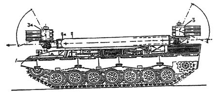
invention it will. b~ ~~~n ih FIB. 1 ~h~~ I make u~~ e~f a standard
tank ohaesie indioated by the numeral ~. for mounting two
telescoping folding arms 2 and 2a with a combat platform ~ $nd 3a
at the rsepeotive upger ex~d c~f each folding arm. ~haaa
t~l~eooping army ar~ extenaion members and art ~wival ~ointad on
S
the bottom to the deck o~ the tank chassis and pivot upwardly
proximal the swivel joint. It thus may be seen that c~rmbat
platforms so mounted may be extended in all directions and may be
held in any intermediate position for deployment, It is
envisioned that each combat platform and its elevating member 2
os 2a will be operated by its own anew ~tea~ber with all movement
being ~.ndiaated on screens internally of they vehicle which era
not shown in the enclosed drawings. It is to be understoad that
an internal system, pr~agarably computer based, will be utilized
to manitor the position of the extension member8 and combat
platforms at all times to provide a safety lockout for both
movement o:~ the combat platforms as well as the :~irine~ e~~ any
weaponry associated therewith such that the combat platforms do
not inadvertently endanger its c~ounterpasrt on the vehicle.
It will b~ appre~aiate~~l that '~la~~ ine3~ependently mcavx~bla
unmanned combat ;platforms ~ and 3a are adble tc~ r~atate 360 degrees
about a vertical axis and are able to t~.p from -2o degrees to X70
degreee~ relative to the horizontal. =t ie contemplated that an
automatic 1~v~3.ing system, of the well~known ~yro~capiG ~Gyp~ or
any other conventianal type will be utilized to keep the combat
platforms in a nox°ma3,l,y level position, subj~ot to manual
override or an ovexx~~d~ occasioned by aiming o~ the ct~znlbat
piatfarm a;t a particular ta~°~et. The weaponry and oth~r
equipment loaded ante the combat plat~ox~ns 3 and 3a may include s
varioty of guided mi~~ilea, light automatic weapons, vidso~
optics, ~ensorg ~c~r daylight ar night-uear~e as we~.l as
transmitter, computer, and alarm systems. Several of these
embodiments are shown in flt3. 11~13. Tt is further contemplated
that both combat platfarms are to be fully operational when the
vchiclc is moving as well as when the vehicle is at rest. at
will also b~ apprecaiated that the ~xtonsion members may serve as
booms w~ex~aa loads hanging members 4 and ~a can be utilized to
attach material to the boom for lifting and aaaneuverirag.
Referring to fiG. 2 it may be seen that the apparatus as shown in
FIG, 1 has a full rangy of ~xt~nsion turning and swiv~llng nor
both elevat~d mechanisms. From FIG. 2 it may be eiearly seen
that the ext~naiona 2 and 2a are tslescsa,pio m~mber~ which extend
wall beyond the gnd lln~s cf the v~~~cls, sap~ns and eguipmant
mounted on combat platforms 3 and ~a can thus be effectively
d~ployed around haug~s or str~st corners by the crew inaiuding
the driver in the vehicle and may be l5shind cover as shown in
FIG. 5b.
FIG. 3 shops that the sect~nsion m~;mb~ra are es;ually movable
at the lateral rangy thus from FrGs. z and 3 it is evident how
both t~l~scapia me~mbsrs z end za may bra used to balanoe the
cyst~m ~ s we~ic~ht and increa~~ ~~tability without sacrificing
d~~loyabilit~r of th~ system. ~h~r~fors, all canc~aivs,b7.e
intermediate positions wittcin t3a~ ~ivot3ng and swi~rsling tangs of
both extension devices should be considered in connection with
the ta~a~rain uecage, As may b~ a~e~n fro~u F7~Gs. 5d and 5e the
advantages rapidly acarus when light and highly ms.neuverable
forms of this invontian are used in exvreme terrain wherein the
vehicle itself may to%e coves while ~.xpvoinq the cvm?~at platforms
for recot~nai~~artaa tax fixe c~ntral. FIG. 3 else shows telescope
extender used as an elevating means ~ax° cambat platfs~x~ms with the
booms mounted one on top of the other with the upper swivel faint
of the lower boom positioned o~ateide the common pivot axis of the
elevating m~chani~~na. In this manner mutut~l c~bst:~uct~.on of
movement is greatly reduc~d and for this type of mount the
centrally lacated turret gearing an existing vgihial~a~ may ba used
here.
Referring to FIG. 4 it may ire seen that sactension member 2
is a folding booze, which is swive3, ~airitad to the deck and
a~ttanaion 2b is a folding extension b~oosn swivel mr~un~ted at the
opposite corner of the da~ak ag t~l~z vehicle. It will Y~e
appreGia,~t~d that the mechanism 2 ar 2a aa~n he replaced by a
separate light elevating mechanism with combat platform, the
~ntira assembly being latched and rerucwrable from the vehicle
rather than permanently mounted thereto. FIG. 5a as a
representation ref such a light e~.evated mechanism displaced frdm
th~a vehicle onto th$ ground. Tt will ?gig appr~ciated that with
this hype of platform and extension a plur2~lity df such devices
may 1a~ maunt~d an a v~hicl~ aging seas a~ tl~~ devices a~ 'the
mechanisms far leading and unlaading th~a oth~r devise. FIG. 5c
shows a wheel--driven fast-moving armored car with two a~,evated
meahanisma mc~xnted one above each other and extending
hari~ontally and sideways with light comlbat pla~.fC~rms thereon,
each ~turnished with such waapanry as guided missiles, light.
9
automatic weapon , or spraying sguipmsnt. FIB 6 shows yet
another atnbadimsnt of my invention wherein a combat platform 3 is
mounted on a pivoting and ~wivsling telescope extension member 2
as in FIG 1 with a second combat platform 3a mounted on a
vertically ext~ndibls linear actuator 2a which is suitable only
for vertical lift but is separately movable from the axt~nei,on
member 2. Both extension mambsrs 2 and 2a ors joined to the
vehicle 1 through a chart rotating meat fi. This mounting
arrangement of the aeaand platform ig fa~arad in embodiments
whets light automatic weapons ar~ ua~d, Eor exempla-for
installation on light highly mobile vshicla~ such a~ jeeps with a
relatively light load carrying capability.
FIG. 7 also shows anathar variant utilizing two telescoping
and awing arms, with the upper t~lsacoping and awing arm
mounted far motion above th~ cab of the underlying vehicle in a
farm of a truck while the second awing arm 2a i~ mounted for
pivotal and xota~3pnal movomsnt Prom th,e bed of the trunk behind
the cab. ~~~srring to F~~. ~ it gay be assn that a combat
vehicle 1 has mounted th~r~on an sxt~ndibls telescope ayatcm 2
Pot omni-dir~ctional movsm~nt about a vertical axis near the left
Front end o~ the vahicZs. The extendible talsgcope ~ystsm is
equipped with twin combat platfarana ~ and a radar ~. A secondary
lifting m~chani~m and combat platform could ba mounted in a
aonvantional turning gear 10 an the vehicle deck ll or on the
rear at 12. ~h~ a~rament ast whioh may bs mQUnted at th~ d~ok 12
oP the vshicl~ 1 is d~piatsd mQra clearly in FAG. s and as may bs
assn more alsarly in FTG. 11, the armament set is provided with
supports 13 and 14 which may bs disengagable from the vehipls 1.
It would be appreciated that the arman~snt set shown in FIGS. 11~
13 have bean dev~loped for aanvsntional combat vehicles and are
to be used in the rearming and modsrnizatiAn o~ such v~hialsg.
These armament sets will considerably increase the capability of
these vehicles and significantly reduce the tim~ required to
utilize the armament systems. 3n FIG. 11 it may bs seen that the
vehidle 1 includes a turret whereon a conventional turret gun is
mounted and to which a armament set consisting of an aleuating
mechanism 2 arid a combat platform with armament 3 is mounted to
the rear of the turret while a second identical set is mounted to
the stern. The a7rmamsnt sat 15 includes a turning and tilting
device is for the combat platform. Tn 1~TG. 12 the turret vehicle
1 is again shown with a stern armament set including a pivoting
extension mombor ~ and a combat platform 3 which is rotatable
about th~ upp~r end of the ~xtension member. The stern armament
sat is mounted in a rotatable rind mounting 17 and also has a
pivot mounting to vary the elevation thereof. Tn FIG. 13 a
container 18 is mounted on a pivot 2n in the same manner ag the
combat platform and extension members shown in the previous
embodiments. It will bs appreciated that the armament set Shawn
in FIG. 1~ with its omni~directional and telescoping elevating
mechanism allows for unimpad~d turning of the turret with the
cannon thus permitting ~avorabls deployment of its combat
platform around vertical border lines of protective covers
3a
available in the terrain. The container 2a Shawn in FTC. 13 may
carry rockets, fuel, fire-fighting- or d~contaminatian~liquids or
jamming equipment against deteotian ox guided projectiles and is
suitable for d~ployment. The ai~e and farm of the container may
be adjusted to combat r~~uir~ments and dependent on
circumstances, the target and guidance system of the combat
vehicle l can be ~~ppl~m~nt~d ar an additional system 19 mounted
an an extension member similar to the combat platforms may ba
carried on beard and raised to desired el~vation. fihe present
invention fsrther contemplates extension members capable of
conducting air through a closed system fr4m the free and of the
extension members to with the vehicle, Theses extension members
would provide air to the crew and engines of the vehicle should
the vehiala become submerged in water. dram the foregoing it
may be sa~n that ~ have described a plurality of various
embadim~nts of my invention which include a combat vehicle with
two elevated m~ahanisms and combat platforms which can be
deployed independently from each ether and which art capable of
combat with several aerial and ground targets simultaneously in
diff~rent dir~atians and at cliff~rent range. It should ba
appreciathd that the vehicle carrying my combat armaments may ba
effectively hidden behind availa~la cover ~hua e~tposing only the
armaments only to hostile fire. a~x~ additional advantage to this
invention relat~s to the elevation of more 'than one elevating
11
m~ah~nism~ v~ith ~omb~t ~rl~~fnxms which are ~xb~ndibl~ info all
diroc~iorm arid allr~~~ fox a mul~3.pl.~ ima~~d3ac~r depl~ym~nt n~
arpaam~n~ .
1~