Note: Descriptions are shown in the official language in which they were submitted.
" 201271~
This invention relates to heavy duty
pneumatic tires, and more particularly to a heavy
duty pneumatic tire having improved traction and
braking performances on wet road surface or wet
performances without damaging resistance to uneven
wear and resistance to stone biting.
The invention will be described with
reference to the accompanying drawings, wherein:
Fig. la is a schematic view of a first
embodiment of the tread pattern
in the tire according to the
invention;
Fig. lb is a schematically sectional view
of an auxiliary groove in the
tread pattern of Fig. la;
Figs. 2a and 2b are graphs showing
relations of shapes of auxiliary
groove and step protrusion to the
resistance to uneven wear,
respectively;
Fig. 3a is a schematic view of a second
embodiment of the tread pattern
in the tire according to the
invention;
Fig. 3b is a schematically sectional view
of an auxiliary groove in the
tread pattern of Fig. 3a;
Figs. 4 to 9 are schematic views of third
to eighth embodiments of the
tread pattern in the tire
according to the invention,
respectively;
~' - 2 -
2~271~
Fig. lOa is a schematic view of the step
protrusion according to the
invention;
Figs. lOb and lOc are schematically
sectional views taken along lines
D-D and E-E of Fig. lOa,
respectively,
Fig. lla is a schematic view of a ninth
embodiment of the tread pattern
in the tire according to the
invention;
Fig. llb is a schematically sectional view
of an auxiliary groove in the
tread pattern of Fig. lla;
Fig. 12 is a schematically sectional view
of another embodiment of the
auxiliary groove according to the
invention;
Figs. 13a to 13d are graphs showing
relations of beveled shapes of
auxiliary groove and step
protrusion to the tread chipping
and the resistance to uneven
wear, respectively;
Figs. 14a, 14b and 15a to 15c are
schematically sectional views of
beveled shapes of the auxiliary
- groove and step protrusion
according to the invention,
respectively;
- 3 -
, ' - - , . . ~ - ,
'' ~ '
201271~
Figs. 16a to 16c are graphs showing the
comparison between the tire
according to the invention and
the conventional tire to the wet
performance, resistance to uneven
wear and resistance to stone
biting, respectively;
Fig. 17a is a schematic view of the tread
pattern in the conventional tire;
and
Fig. 17b is a schematically sectional view
of a part of the tire shown in
Fig. 17a.
In the pneumatic tire having lug grooves
separated from each other in the circumferential
direction of the tire and extending substantially in
the widthwise direction of the tire and island
portions defined by such lug grooves or a lug
pattern, traction force and braking force are
excellent, so that such tires are widely used as a
tire for truck and bus, a tire for construction
vehicle and the like.
On the other hand, there is increased a
chance of running truck, bus and the like provided
with such a tire at a high speed according to the
enhancement of road circumstances, and hence it is
highly demanded to have steering property and
stability.
In order that such a demand is satisfied
by the conventional technique, as shown in Fig. 17a,
lug grooves 14 are formed in each of half regions in
- 4 -
2~12715
widthwise direction of a tread portion 12 of a tire
10 at a shifting of about half pitch in the
circumferential direction. Further, a part of the
lug groove 14 substantially extending from a
shoulder portion 16 toward a central region of the
tread portion 12 in the widthwise direction is bent
toward the circumferential direction of the tire.
Then, the lug grooves 14, 14 formed in the
respective half regions of the tread portion 12 are
connected to each other through a subsidiary groove
18 slantly crossed with respect to the equator P of
the tire, while the bent portions of the two lug
grooves 14 formed in each half region of the tread
portion and separated from each other in the
circumferential direction of the tire are connected
to each other through another subsidiary groove 20
slantly crossed with respect to a plane separated in
parallel to the equatorial plane of the tire, and
consequently an island portion 22 is defined by
these subsidiary grooves 18 and 20.
In such a conventional tire 10, the edge
of the island portion 22 is slantly crossed with the
equatorial plane or the plane separated in parallel
to the equatorial plane, so that not only the
traction performance and braking performance are
improved but also the lateral slipping of the tire
against the movement in the widthwise direction of
the tire is suppressed to contribute the improvement
of the steering property and stability of the tire.
Furthermore, when the tire is run on a wet road
surface, the above edge develops a so-called edge
- 5 -
- ~ ;
.. . . . , ~
.
-
--- 2012713
effect that the edge cuts a water film formed on the
road surface to contact with the road surface so
that the wet performances are improved.
As shown in Fig. 17b, the depths of the
subsidiary grooves 18 and 20 from the tread surface
are about 30% of the depth of the lug groove 14 to
ensure the rigidity of the island portion 22 defined
by these subsidiary grooves 18 and 20 at the
kicking-out side edge, whereby the uneven wear at
the kicking-out side region of the island portion 22
during the running of the tire is prevented.
However, the depths of the subsidiary
grooves 18 and 20 formed in the central region of
the tread portion lZ are shallower than that of the
lug groove 14, so that the drainage performance of
the tire is degraded as the wearing of the tread
surface promotes during the running and hence the
given object can not be achieved.
Furthermore, once the wearing is caused at
the edge of the island portion 22 in the central
region of the tire tread, the uneven wear gradually
proceeds due to the difference in the size of the
tire, and also the edge is worn, so that the edge
effect cannot be expected and consequently the
steering property and stability on wet road surface
are degraded.
Under the above circumstances, it is an
object of the invention to provide a novel pneumatic
tire capable of developing the wet performances
without damaging the resistance to uneven wear and
the resistance to stone biting in the tire.
- 6 -
-- 201271~
In order to achieve the above object, in
the pneumatic tire according to the invention, an
auxiliary groove connecting at least two lug grooves
located in each half region of a tread portion and
separated from each other in the circumferential
direction of the tire to each other is formed in a
central region of the tread portion within a range
of about 50~ of a tread width, and a step protrusion
extending along the auxiliary groove is arranged at
least inside the auxiliary groove, and groove width
Wl of the auxiliary groove, groove depth dl from
tread surface, width W2 of step protrusion surface
and height d2 from the bottom of auxiliary groove to
the surface of step protrusion satisfy relationships
of (Wl-W2)/2Wl<0.2 and 0.70<d2/dl<0.95.
In a preferred embodiment of the
invention, at least an end of the step protrusion is
protruded in the lug groove so as to satisfy a
relationship of O<al/a2<1 (wherein al is a
protruding length of the step protrusion into the
lug groove and a2 is a width of the lug groove). In
addition to the auxiliary groove, the respective lug
grooves located at both half regions of the tread
portion are further connected to each other through
a slant groove slantly crossed with the equator of
the tire. In this case, the slant groove is also
provided with a step protrusion having the same
structure as in the auxiliary groove.
In another preferred embodiment of the
invention, the protruding portions of the step
protrusions each protruding into the adjoining lug
.: - 7 -
2~271~
groove in the circumferential direction are
integrally united with each other along the lug
groove to continuously extend zigzag in the
circumferential direction, and also it is preferable
to satisfy a relationship of 90<~,~160 (wherein
~ is an angle between the upper surface of the step
protrusion and the protruding end face of the
protruding portion and ~ is an angle between the
upper surface of the step protrusion and the side
face of the protruding portion).
Moreover, it is advantageous that the side
wall of the auxiliary groove and/or step protrusion
is comprised of a rising segment standing up
substantially in perpendicular to the bottom of the
auxiliary groove and a beveled segment slantly
crossing with the rising segment and connecting to
the surface of the tread portion or the step
protrusion.
When the tire according to the invention
is run on road under a loading, the tread portion
and hence the step protrusion and island portion
comes into contact with ground, so that the
shearing force is caused at the kicking-out
sides of the step protrusion and island
,/~-
~ . "
~ - 8 -
2 ~ 2 ~ ~ ~
portion in a direction opposite to the rotating
direction of the tire.
However, it is considered that the shearing
force produced in unit area of the tread portion is
05 approximately constant during the rotation of the tire,
while the upper surface of the step protrusion is
dragged against road surface because the length of the
upper surface of the step protrusion in the
circumferential direction of the tire is shorter than
that of the tread surface. As a result, a larger
shearing force is produced at the step protrusion in a
direction opposite to the rotating direction of the tire
and the shearing force produced in the island portion
becomes smaller.
Consequently, the step protrusion formed on the
tread surface is worn instead of the island portion,
whereby the progress of wearing at the island portion,
particularly its edge can effectively be suppressed, so
that the tread surface can be worn approximately
ao uniformly.
Since the edge of the island portion is not
unevenly worn, even when the wearing of the tread
surface proceeds, the sufficient edge effect can be
maintained, whereby the steering property and stability
on wet road surface are ensured.
Furthermore, when the slant groove is arranged
2 ~ ~ 2 f ~ 5
so as to connect the respective lug grooves located in
both half regions of the tread portion to each other and
provided with the step protrusion in addition to the
auxiliary groove, the rigidity of the step protrusion in
05 the circumferential direction of the tire is improved as
compared with the case of using only the auxiliary
groove, so that the free deformation of the step
protrusion is more restrained in the contacting of the
tire with ground. As a result, the shearing force
produced in the step protrusion in a direction opposite
to the rotating direction of the tire is increased,
while the shearing force produced in the island portion
is made smaller, whereby the resistance to uneven wear
can be more improved.
In the latter case, the step protrusion is
arranged inside each of the auxiliary groove and the
slant groove, so that the drainage performance is
somewhat degraded. However, the edge component of the
island portion is increased owing to the presence of the
auxiliary groove and slant groove, so that the wet
performances are not damaged.
On the other hand, at least an end, preferably
both ends of the step protrusion arranged inside the
auxiliary groove therealong is protruded into the
respective lug groove, whereby the rigidity of the step
protrusion in the circumferential direction of the tire
- 10 -
.
can be more enhanced. Of course, the rigidity of the
step protrusion in the circumferential direction of the
tire is further enhanced by integrally uniting the
protruding portions of the step protrusions protruded
05 into the lug grooves with each other along the lug
grooves or by selecting the angle ~ between the upper
surface of the step protrusion and the protruding end
face of the step protrusion and the angle ~ between the
upper surface of the step protrusion and the side face
of the protruding portion so as to satisfy the
relationship of 90~,~160, whereby the uneven wear
of the island portion can be suppressed and the wet
performances of the tire can be improved.
Moreover, when the side wall of the auxiliary
groove and/or the step~protrusion is comprised of a
rising segment substantially vertically stood up from
the bottom of the auxiliary groove and a beveled segment
extending from the rising segment and slantly crossing
with the tread surface, the problem of stone biting
resulted from the formation of the step protrusion
inside the auxiliary groove and/or the lug groove can be
advantageously solved.
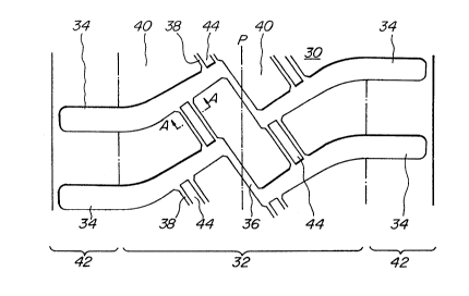
In Fig. la is shown a first embodiment of the
heavy duty pneumatic tire according to the invention.
26 This tire 30 has a so-called lug pattern, in which lug
grooves 34 are arranged in each half region of a tread
- 2~7~ ~
portion 32 in the widthwise direction of the tire and in
substantially symmetry with each other in both half
regions with respect to an equator P of the tire and
separated away from each other in the circumferential
05 direction, and slant grooves 36 each slantly crossing
with the equator P are arranged so as to connect ends of
the respective lug grooves 34 located in both half
regions of the tread portion to each other, and
auxiliary grooves 38 are arranged so as to connect an
end of lug groove 34 located in one half region of the
tread portion to a middle of the adjoining another lug
groove 34 located at the same half region of the tread
portion and separated from the above lug groove in the
circumferential direction of the tire, and island
16 portions 40 are defined by these lug grooves 34, slant
grooves 36 and auxiliary grooves 38. The internal
structure of the tire is a general radial structure.
Moreover, a half portion of the lug groove 34 is slantly
extended with respect to the equator P in the half
region of the tread portion and the other half portion
is extended outward in the widthwise direction of the
tire and opened to a shoulder portion 42.
The slant groove 36 and auxiliary groove 38
contribute to the improvement of the drainage
performances in the tire, while the edge of the island
portion 40 defined by the slant groove 36 and the
-12-
~2~
,
auxiliary groove 38 or an edge line slantly extending
with respect to the equator P regulates the movement of
the tire in the widthwise direction thereof as
previously mentioned. In the illustrated embodiment,
05 the depth of each of the auxiliary groove and the slant
groove is substantially equal to that of the lug
groove 34.
According to the invention, as shown in Fig. lb
by a section taken along a line A-A, a step protrusion
44 is formed inside the auxiliary groove 38, which
connects the adjoining lug grooves 34 separated in each
half region of the tread portion 32 in the circumfer-
ential direction of the tire to each other, along the
auxiliary groove 38. The upper surface of the step
16 protrusion 44 i located inward from the upper surface
of the tread portion 32 in the radial direction thereof,
whereby level different portions extending along the
auxiliary grooves 38 are formed on the upper surface of
the tread portion 32.
The reason why the step protrusion 44 is formed
along the auxiliary groove 38 is due to the fact that
the step protrusion 44 is positively worn instead of the
island portion 40, particularly the edge thereof during
the rotation of the tire under loading and hence the
tire is substantially uniformly worn over its whole to
still ensure the edge effect at the edge of the island
portion 40 even in the worn tire.
Furthermore, when the width of the auxiliary
groove 34 is Wl, the depth from the surface of the tread
portion 32 to the bottom of the auxiliary groove 38 is
05 dl, the width of upper surface of the step protrusion 44
is W2 and the height from the upper surface of the step
protrusion 44 to the bottom of the auxiliary groove 38
is d2, they are selected so as to satisfy the following
inequalities (1) and (2):
( Wl~W2 ) /2Wl<o.2... (1)
0.70<d2/dl<0.95...... (2)
~ he reason why the width Wl of the auxiliary
groove 38 and the width W2 of the upper surface of the
step protrusion 44 are selected so as to satisfy the
inequality (1) is dué to the fact that when a half value
of a ratio of difference between width Wl of the
auxiliary groove 38 and width W2 of the upper surface of
the step protrusion 44 to width Wl of the auxiliary
groove 38 or (Wl-W2)/2Wl exceeds 0.2, the resistance to
uneven wear is degraded as shown in Fig. 2a.
Furthermore, the reason why the depth dl from
the surface of the tread portion 32 to the bottom of the
auxiliary groove 38 and the height d2 from the upper
surface of the step protrusion 44 to the bottom of the
auxiliary groove 38 are selected so as to satisfy the
inequality (2) is due to the fact that when the ratio of
-14-
-- 2 ~ ~ 2
height d2 of step protrusion to depth dl of auxiliary
groove is less than 0.75 and more than 0.95, the
resistance to uneven wear in the tire is degraded as
shown in Fig. 2b.
05 Moreover, the tire showing a resistance to
uneven wear of 100 in Figs. 2a and 2b is the
conventional tire having a tread pattern shown in
Fig. 17.
According to the invention, the auxiliary groove
38 including the step protrusion 44 therein is arranged
in a central region of the tire tread portion 32 within
a range of approximately 50% of tread width inclusive of
the equator P because the uneven wear is particularly
apt to be caused in such a central region of the tread
portion. Moreover, it is preferable that the step
protrusion 44 has a length of not less than 30 mm and a
surface width W2 of not less than 10 mm for providing
the rigidity durable to the deformation of the tire.
In Fig. 3a is shown a second embodiment of the
tire according to the invention. Concretely, the
invention is applied to the conventional tire shown in
Fi.g 17.
In the tire 50 of this embodiment, at least two
adjoining lug grooves 14 located at each half region of
26 the tread portion 12 are connected to each other through
each of auxiliary grooves 38a slantly crossing with the
-15-
~2~ ~
equator P and arranged in each half region of the tread
portion and shifted at a half pitch in the circumfer-
ential direction of the tire, wherein the end of one of
the two lug grooves toward the center of the tread
05 portion is connected to a middle of the other adjoining
lug groove, and the ends of the respective lug grooves
arranged in both half regions of the tread portion and
shifted at a half pitch in the circumferential direction
are connected to each other through a slant groove 38b
slantly crossing with the equator P, and step
protrusions 44 are formed in each of these auxiliary
grooves 38a and the slant grooves 38b. In this case,
the depths dl of the auxiliary groove 38a and the slant
groove 38b are equal to the depth of the lug groove 14.
16 For convenience' sake, the same part of the tire as in
Fig. 17 is indicated by the same numeral as in Fig. 17.
Moreover, Fig. 3b shows a section of the
auxiliary groove 38a and slant groove 38b taken along
lines B-B and C-C in Fig. 3a. It is a matter of course
that the width Wl and depth dl of each of the auxiliary
groove 38a and slant groove 38b and the width W2 and
height d2 of the step protrusion 44 satisfy the above
inequalities (1) and (2).
In Fig. 4 is shown a third embodiment of the
tire according to the invention. That is, the tire 52
is a modified embodiment of the tire shown in Fig. la,
-16-
2 ~
in which at least an end of the step protrusion 44 is
protruded into the lug groove 34. In the illustrated
embodiment, both end portions of the step protrusion 44
are protruded into the respective lug grooves 34.
05 Preferably, the length a1 of the protruding portion 44a
of the step protrusion 44 into the lug groove 34 and the
width a2 of the lug groove 34 including the protruding
portion satisfy a relation of O<a1/a2<l.
In the tire 52 wherein at least an end of the
step protrusion 44 is protruded into the lug groove 34,
not only the rigidity of the step protrusion inclusive
of the protruding portion is enhanced in the circum-
ferential direction of the tire but also the length and
hence the volume of the step protrusion is increased, so
16 that the load acting to the unit volume of the step
protrusion during the running of the tire can be
reduced. Therefore, when the tread of the tire 52 comes
into contact with ground, the movement of the step
protrusion 44 can be controlled to more concentrate the
shearing force produced in a direction opposite to the
rotating direction of the tire into the step protrusion
44, so that the uneven wear at the island portion 40,
particularly the edge thereof defined by the lug groove
and the auxiliary groove can be more reduced.
.25 Moreover, it is confirmed from experiments that
the reason why the length a1 of the protruding portion
-17-
2~27';~ 3
of the step protrusion 44 and the width a2 of the lug
groove 34 including this protruding portion must satisfy
the relation of O<al/a2<l is due to the fact that when
a1/a2=0 is standard, the resistance to uneven wear is
05 improved as the value of al/a2 becomes large and is
maximum at al/a2~0.8 and lowers to the level of al/a2=0
in case of al/a2=l.
Of course, the step protrusion may be protruded
at a width approximately equal to that of the auxiliary
groove 38. Further, the protruding portion 44a of the
step protrusion 44 may be extended in the lug groove 34
therealong as shown in Fig. 5 showing a fourth
embodiment of the tire according to the invention.
In the latter tire 54, the rigidity in circumferential
direction and the volume of the step protrusion 44 can
further be increased to more improve the resistance to
uneven wear.
In Fig. 6 is shown a fifth embodiment of the
tire according to the invention. In this tire 56, the
protruding portion of the step protrusion 44 protruded
into the lug groove 34 is extended inward in the
widthwise direction of the tire along the lug groove 34
and integrally united with the protruding portion of the
other step protrusion protruded into this lug groove 34
in each half region of the tread portion 32. That is,
the step protrusion 44 is continuously extended zigzag
-18-
,, .,.. :. . ... .. ; , . .
y~
r -
in the circumferential direction of the tire along the
auxiliary groove 38 and the lug groove 34. Even in such
a tire 56, the resistance to uneven wear can further be
improved owing to the increase of the rigidity and
05 volume of the step protrusion 44 in the circumferential
direction of the tire.
Figs. 7 to 9 show sixth to eighth embodiments of
the tire according to the invention. These tires are
modified embodiments of the tire shown in Fig. 3a,
respectively. In this case, the same part of the tire
as in Figs. 3a and 17 is indicated by the same numeral
as in Figs. 3a and 17.
The tire 58 of Fig. 7 is different from the tire
50 of Fig. 3 in a point that both end portions of the
16 step protrusion 44 are protruded from the auxiliary
groove 38a into the lug grooves 14, respectively, but
the step protrusion 44 is not existent in the slant
groove 38b.
The tire 60 of Fig. 8 is different from the tire
50 of Fig. 3 in a point that the step protrusion 44
formed in the slant groove 38b is protruded at both ends
toward the auxiliary grooves 38a every other slant
groove including the step protrusion therein and
integrally united with the step protrusions formed in
the respective auxiliary grooves 38a.
The tire 62 of Fig. 9 is different from the tire
-19-
- . . .. ; .. . - -. - . . . .... , ., .... - . .. . .
~ h ~i~
50 of Fig. 3 in a point that the step protrusions 44
formed in the auxiliary grooves 38a and the slant
grooves 38b are integrally united with each other along
the auxiliary groove 38a, slant groove 38b and lug
05 groove 14 to continuously extend zigzag in the
circumferential direction of the tire.
In any case of Figs. 7 to 9, it is a matter of
course that the resistance to uneven wear can be more
improved owing to the more increase of the rigidity and
volume of the ~tep protrusion 44 in the circumferential
direction of the tire. Moreover, since the step
protrusions are arranged in the auxiliary groove, slant
groove and/or lug groove, the drainage performance is
degraded due to the existence of the step protrusion in
1~ these grooves, but the edge components at the tread
surface inclusive of the step protrusion against the
road surface are increased, so that the degradation of
the drainage performance is compensated by the edge
effect of these edge components and the improvement of
wet performances can be expected.
In the above embodiments, it is favorable that
an angle between the upper surface of the step
protrusion 44 and the protruding end face of the step
protrusion into the lug groove and an angle 3 between
the upper surface of the step protrusion and the side
face of the protruding portion (see Figs. lOa to lOc)
-20-
r~ d ~
are selected to satisfy a relation of 90~,B~160.
The reason why the angles ~, B are selected from
the above range is due to the fact that the rigidity of
the protruding portion of the step protrusion is
05 enhanced to control the movement of the step protrusion
as a whole, whereby a percentage of shearing force
acting to the step protrusion at the tread surface in a
direction opposite to the rotating of the tire during
the running of the tire is increased and a percentage of
the shearing force acting to the island portion is
decreased to control the occurrence of uneven wear.
When the angles ~, ~ are less than 90, the protruding
portion of the step protrusion and hence the step
protrusion itself are apt to be deformed, and
16 consequently the percentage of the shearing force acting
to the island portion is increased to cause uneven wear
at the island portion, particularly the edge thereof.
When the angles ~, 3 are larger than 160, the
drainage performance of the lug groove portion located
at the shoulder portion is degraded to degrade the wet
performances.
AS mentioned above, the resistance to uneven
wear and the wet performances can be improved by
arranging the step protrusions along the auxiliary
26 groove, slant groove and/or lug groove, but it will be
anticipated to cause problems of stone biting between
'- 2 ~ Y ~
the step protrusion and the auxiliary groove, slant
groove or lug groove and of tread chipping due to this
stone biting.
In order to solve these problems, in a tire 63
05 of a ninth embodiment shown in Fig. lla, the step
protrusion 44 formed in the auxiliary groove 38 is
comprised of a rising segment 44b standing up in a
direction substantially perpendicular to the bottom of
the auxiliary groove 38 and a beveled segment 44c
extending from the rising segment 44b and slantly
crossing with the upper surface of the step protrusion
44 as shown in Fig. llb showing a section taken along a
line F-F of Fig. lla.
In this case, when the width of the beveled
16 segment 44c is W3, the depth of the beveled segment 44c
from the upper surface of the step protrusion is d3, the
width of the step protrusion 44 is W2 and the height of
the step protrusion 44 from the groove bottom is d2,
they are selected to satisfy the following inequalities
(3) and (4), preferably the following inequalities (3')
and (4')':
0.2Sd3/d2S0.8 ....... (3)
0.lsW3/W2s0.8 ....... (4)
0.4~d3/d2S0.6 ....... (3')
26 o.4Sw3/w2so.6 ....... (4')
When the ratio d3/d2 is more than 0.8 or the
-22-
- 2 ~
ratio W3/W2 is less than 0.1, the rigidity of the step
protrusion is lowered to degrade the resistance to
uneven wear, while when the ratio d3/d2 is less than 0.2
or the ratio W3/W2 is more than 0.8, the resistance to
05 stone biting is not improved.
On the other hand, as shown in Fig. 12, the
beveled segment 38c may be formed in the side wall of
the auxiliary groove 38 instead of the beveled segment
44c. In this case, when the width of the beveled
segment 38c is W4 and the depth of the beveled segment
38c from the tread surface is d4, they are selected to
satisfy the following inequalities (5) and (6),
preferably the following inequalities (5') and (6'):
0.1~d4/dl~0.7 ....... (5)
16 0.05~W4/W1~0.5....... (6)
0.1~d4/dl~0.7 ....... (5')
0.05~W4/W1~0.3....... (6')
As shown in Figs. 13a and 13b, when the ratio
d4/dl is not less than 0.1 and the ratio W4/Wl is not
less than 0.05, the effect of preventing the tread
chipping due to the stone biting is improved.
On the other hand, as shown in Figs. 13c and
13d, when the ratio d4/dl is more than 0.7 and the ratio
W4/Wl is more than 0.5, the resistance to uneven wear is
26 degraded.
Therefore, when each of the ratios d4/dl and
-23-
W4/Wl is within the above range, the side face of the
auxiliary groove 38 may have a sectional shape as shown
in Figs. 14a and 14b.
Furthermore, according to the invention, each of
oS the side walls of the auxiliary groove 38 and the step
protrusion 44 may be provided with the beveled segments
38c and 44c as shown by section in Figs. 15a to 15c.
In any case, when the step protrusion and/or the
auxiliary groove are provided at the ide wall with the
beveled segment, the widths W3 and ~4 and the depths d3
and d4 are selected to satisfy the above inequalities
(3) to (6~.
The following example is given in illustration
of the invention and is not intended as limitation
thereof.
Example
In order to examine the wet performances,
resistance to uneven wear and resistance to stone biting
of the tire, the comparative test is made by using the
ao invention tires having the step protrusion in the
auxiliary groove and the conventional tire having no
step protrusion to obtain results as shown in Figs. 16a
to 16c. Mo~eover, all of the tires have a radial
structure and a tire size of 10.00 R20.
26 ~ Test tire
Invention tire 1:
-24-
This tire has a tread pattern shown in Fig. 1,
wherein the tread width is 204 mm, the maximum and
minimum widths of the lug groove are 20 mm (shoulder
portion) - 12 mm (central region), the maximum and
05 minimum depths of the lug groove are 20.5 mm (shoulder
portion) - 15.4 mm (central region), the interval
between lug grooves in circumferential direction is
66 mm, the width (W1) of the auxiliary groove is 15 mm,
the depth (dl) of the auxiliary groove is 16 mm, the
width (W2) of the step protrusion is 13 mm, the height
(d2) of the step protrusion is 14 mm, the length of the
step protrusion is 40 mm, the width of the slant groove
6 mm and the depth of the slant groove 9 mm.
Invention tire 2:
This tire has a tread pattern shown in Fig. 4,
wherein the dimensions are equal to those of the
invention tire 1 except that the protruding length al of
the step protrusion is 20 mm, and the angles ~, 3 are
115 and 130, respectively.
Invention tire 3:
This tire has a tread pattern shown in Fig. 6,
wherein the step protrusion is continuously extended
zigzag in the circumferential direction of the tire and
the other dimensions are equal to those of the invention
tire 1.
Invention tire 4:
-25-
This tire has the same tread pattern and
dimensions as in the invention tire 1 except that the
auxiliary groove has a sectional shape shown in Fig. 12
and the width (W4) and depth (d4) of the beveled segment
05 are 7 mm and 5 mm, respectively.
Conventional tire:
This tire has a tread pattern shown in Fig. 17
containing no step protrusion in the auxiliary groove.
~ Test method
Wet performance:
Each of the test tires is mounted on a vehicle
at various states ranging from a new state to a
sufficiently worn state and subjected to a turning test
on a constant circle at a water depth of 5 mm, during
which a lateral acceleration speed is measured.
The measured value is evaluated by an index. The larger
the index value, the better the wet performance.
Resistance to uneven wear:
Each of the test tires is assembled into a
normal rim, mounted onto a vehicle under normal internal
pressure and a normal load, and run over a distance of
30,000 km. Thereafter, the worn amount at the tread
surface is measured. The measured value is evaluated by
an index. The larger the index value, the better the
resistance to uneven wear.
Resistance to stone biting:
-26-
2 ~ ~ 2 ~ _ ~
Each of the test tires is assembled into a
normal rim, mounted onto a vehicle under a normal
internal pressure and a normal load, and run on rough
road over a distance of 5,000 km. Thereafter, the
05 number of stones bitten in grooves is measured.
The smaller the stone number, the better the resistance
to stone biting.
Moreover, the test results are shown in
Figs. 16a to 16c.
As seen from Figs. 16a to 16c, the wet
performance rapidly lowers in the conventional tire as
; the wearing proceeds to a certain extent, while the
tires according to the invention can develop the
sufficient wet performance even at a fairly worn state.
Furthermore, when the tires according to the invention
are compared with the conventional tire, the occurrence
of uneven wear can be controlled and also the resistance
to stone biting can sufficiently be compensated though
the step protrusion is arranged in the auxiliary groove.
As mentioned above, according to the invention,
heavy duty pneumatic tires having improved wet
performances and causing no degradation of wet
performances even at a worn state can be provided
without damaging the resistance to uneven wear and
resistance to stone biting in the tire.
-27-