Note: Descriptions are shown in the official language in which they were submitted.
2 0 1 2 ~
INSTANTANEOUS POWER MEASURING APPARATUS
FOR ~ICYCLE ERGOMETER
BACRGRO~ND OP T~E INVENTION:
This invention relates to a method of and an apparatus for
measuring the physical strength of a person, and more
particularly to a method of and an apparatus for measuring the
instantaneous power exerted by a person in a highly safe manner
and on the basis of a power theory, without imposing an
excessive burden on the sub~ect.
Recently, an increased interest in physical strength has
been aroused, and there has now been a demand for a method of
and apparatus for measuring such physical strength easily and
safely.
The following questions have been posed with respect to
conventional physical strength tests, such as, for example a
vertical ~ump test, a reciprocal ~ump test and a dorsal muscle
test.
(1) Since various functions are appraised ~eparately, it
is difficult to link the test results with a synthetic
appraisal.
(2) Appraisal standards are ambiguous. For example, with
respect to a vertical ~ump, the appraisal standard is the
height to which one can ~ump; however, this is an index of the
performance, and is an indirect and sub~ective one.
(3) There is no standardized scientific proof.
~'
~ - 1 - `,
--` 201~956
(4) Unusual movements are involved, and the load involved
is large, and in~uries are liable to occur.
In connection with the above items (1) to (3), it i8 useful
to study the standardization of the indices of physical
strength by the power theory. According to power theory,
physical strength is measured as the capacity of energy
(integrated value of the power), or the power is measured as
indices. Forms of development of power are classified
according to energy developing mechanisms in a living body, and
with respect to each development form, the upper limit value of
the power is measured while maintaining the corresponding
energy developing mechanism, and this is used as an index of
the physical strength in the corresponding energy developing
mechanism. Specifically, the measurements are carried out in
the following manner:
(a) Oxygen-present energy mechanism
Duration: Infinite
Appraisal of upper limit power: Power available at
75% of the maximum
heat rate, etc.
Main factor for energy generation: Oxygen
(b) Lactic acid-type anoxia energy mechanism
Duration: About 30 seconds
Appraisal of upper limit power: Average power,
critical power, etc.
Main factor for energy generation: Glycogen
Z~1~956
(c) Non-lactic acid-type anoxia energy mechanism
Duration: About 7 seconds
Appraisal of upper limit power: The optimum value
determined by speed and
developing foxce of the
peak power around
approximately 5 to 6
seconds.
~ain factor for energy generation: ATP-CP type chemical
energy.
The measurement by a bicycle ergometer based on the power
theory has also been proposed or put into practice.
--A technique in connection with the above energy mechanism~
(a) and (c) has been proposed by Combi Corporation (Japanese
Patent Examined Publication No. Hei. 1-42694), and there are
known "Aerobike" and "Power max" (both of which are registered
and pending trademarks of Combi Corporation; the former is
Japanese Trademark Registration No. 1840771, and the latter i8
Japanese Trademark Publication No. 61-42348) to which the above
technique is applied. As to the energy mechanism (b), the
Wingate test is known. Such power measurement utilizing a
bicycle ergometer is desirable in that the pedaling motion can
~e said to be analogous to a running motion, the chance of
in~ury is reduced because of a rhythmical motion, the power can
be produced efficiently, and bicycling has long been popular.
-
20~95~S
snMMARr OE THE INVENTION
As described in detail hereinafter, the present invention
resides in measuring instantaneous power (that is, initial
power or starting power in the energy mechanism (c)) by the use
of a bicycle ergometer, on the basis of the power theory. Such
technical concept has not heretofore been known.
More specifically, in the measurement by the non-lactic
acid-type anoxia energy mechanism (c), which is known as a
shor~-time power measurement, the power is appraised
immediately before the energy is exhausted, that is, 5 to 6
seconds after pedaling is started. On the other hand, in the
present invention, the power at the time of starting, that is,
within 5 seconds, is measured. In addition, in the measurement
by the non-lactic acid-type anoxia energy mechanism (c), the
results of the calculated power are subjected to variations
when the measurement unit for power calculation is shortened,
and therefore the measurement unit is long on the order of not
less than 0.5 seconds. However, in the present invention, as
later described, the power measurement calculation is carried
out during the time from the start of the kicking of the pedal
to the end of the pedal kicking, and therefore the measurement
time unit is within 0.5 seconds. Accordingly, instead of the
appraisal of the average power over a long time, the appraisal
of a localized power can be done.
-- 201~95~,
~ he present invention has been made in view of the
foregoing, and an ob~ect of the invention is to provide a
method of and an apparatus for measuring instantaneous power
based on the power theory, utilizing a bicycle ergometer.
Therefore, the present invention is proved theoretically, and
it is expected that a simple and safe measurement can be
carried out.
Another ob~ect is to provide a method and an apparatus in
which a full-power pedaling time is short, on the order of
within 5 seconds, as compared with the power measurement by the
conventional non-lactic acid-type anoxia energy mechanism, thu~
considerably reducing the burden on the subject, and the
instantaneous power is measured in a more optimal manner based
on the peak value of the power around 2 seconds after the start
of the pedaling.
In the present invention, in order to achieve the above
ob~ects, there is used a bicycle ergometer equipped with an
inertia mechanism having an inertia with respect to a
rotational driving movement. The rotational speed of a rotary
member of said bicycle ergometer is measured at predetermined
short time intervals. In accordance with the measurement value
of the rotational speed, a lapsed time between a point of start
of increase of the rotational speed and a point of end of
increase thereof, and a finite difference of said lapsed time
are found, and also the rotational speed between said point of
2(~ 9S~;
start of increace and said point of end of increase during said
lapsed time is found as an average rotational speed. In
accordance with these calculated values, ~he power with respect
to said inertia mechanism is determined, and in accordance with
this power, the instantaneous power is appraised.
Also, in the present invention, a regression formula with
respect to the average rotational speed of a finite difference
of said lapsed time as well as a regression formula with
respect to the average rotational speed of a finite difference
of said rotational speed are found, and the power with respect
to said inertia mechanism is obtained by these regression
formulas as a function of said average rotational speed, and
the m3ximum value of the power with respect to sàid inertia
mechanism is calculated by the function. With this
arrangement, errors due to variations in pedaling, etc., can be
removed, thereby providing an accurate measurement of the
instantaneous power.
Further, in the present invention, the brake torque is
positively used, so that the instantaneous power can be
measured accurately in a wide variety of forms.
BRIEP DESCRIP~ION OF THE DRAWINGS
Fig. 1 is a diagrammatical view showing the overall
construction of a preferred embodiment of the present
invention;
-- 6 --
20129S6
Fig. 2 is a plan view showing a panel of a control box of
Fig. l;
Fig. 3 is a block diagram of one example of circuitry of
the embodiment of Fig. 1;
Figs. 4(A), 4(B), 5(A), 5(B), 7(A), 7(B) and 7(C) are
graphs showing the measurement principles of the embodiment of
Fig. l;
Fig. 6 is a view showing the angular position of rotation
of similar pedals la; and
Fig. 8 is a flow chart for explaining the operation of the
embodiment of Fig. 1.
DETAILED DESCRIPTION OF THE PREFERRED EMBODrMENT
A preferred embodiment of the invention will now be
described with reference to the drawings.
First, the principle of the measurement will be described,
referring to the general construction of an apparatu~ of this
embodiment.
A. Princi~le of Measurement
Fig. 1 shows the overall construction of the appaxatus of
this embodiment. A bicycle ergometer 1 includes a load device
unit 2 (Fig. 3), which makes use of eddy current loss. A brake
torque is adapted to be applied to pedals la. A control box 3
is mounted on the front of the bicycle ergometer 1 (for
example, at a handle). The load device unit 2 feeds a signal
201~95~;
representative of the rotational speed of the pedal la to the
control box 3, and in accordance with this signal, the control
box 3 displays an appraisal value of an instantaneous power,
etc. The control box 3 also feeds a control signal to the load
device unit 2 so as to ad~ust the brake torque. Detailed
construction and operation of the control box 3 will be
described later.
A belt lb or the like is attached to a saddle of the
bicy~le ergometer 1, so that the sub~ect is not allowed to
pedal in a standing-up condition, so as to ensure an accurate
measurement.
When the subject pedals the bicycle ergometer 1 of Fig. 1
at full power in order to make a measurement of instantaneous
power, the measurement value of the rotational speed of the
pedal la varies, for example, as indicated by (a) (point of
start of increasQ of the rotational speed) and (b) (point of
end of increase of the rotational speed) in Fig. 4A. The
measurement value of the time difference (differential) with
respect to the rotational speed of the pedal la varies as shown
in Fig. 4B.
As is conventionally known, the peak of the power appears
around 2 seconds after the start of a full-power pedaling of a
bicycle ergometer, and a stable uniform motion is obtained 4 to
5 seconds after the start. It is known that the instantaneous
value of the power peak appearing at this time varies
20~9~6
significantly under the influence of the inertia. Therefore,
conventionally, the power is calculated from the rotational
speed and the brake force, obtained 4 to 5 seconds after the
above start (when the influence of the inertia becomes-small),
and this calculated power is appraised as the non-lactic acid-
type anoxia power. However, for appraising the instantaneous
power, it is more desirable to use the power of the starting
peak. Because of the analogousness to a running motion, this
peak power corresponds to the start of a dash in a short-
distance run.
In this embodiment, the full-power pedaling is done for
only 4 to 5 seconds after the start, and the rotational speed
of the pedal la during that time is properly analyzed, thereby
accurately calculating the peak power.
Fig. 5 shows the torque used for accelerating the inertia
mechanism of the bicycle ergometer 1 when driving the pedal la
from a point near to an upper dead point U to a point near to
a lower dead point L against the brake torque. More
specifically, Fig. 5B diagrammatically shows the torque
obtained by subtracting the brake torque from the torque
applied by the sub~ect to the crank of the pedal la in the
rotational direction, and Fig. 5A diagrammatically shows the
rotational speed of the pedal la.
- 20129S6
Here, when an equation of the rotational motion is applied
to the bicycle ergometer having the inertia, the following is
established:
d~
J . - = T - T~ -- (1)
where J represents a moment of inertia (kg.m.s2) of a
flywheel on a part of the pedal, ~ represents the angular
velocity (rad/s) of the pedal, T represents the torque (kgm)
applied to the crank by the subject in the rotational
direction, and T~ represents the brake torque (kgm) on the
pedal.
The formula (1) is modified into the following formula (2):
dN
k ~ T ( 2 )
dt
where N represents the number of revolutions (rpm) of the
pedal la, ~T is equal to T - T~, and k is equal to (2~/60)J.
As shown in Fig. 6, ~T becomes positive at time tl
immediately after the upper dead point U, and becomes negative
at time t2 immediately after the lower dead point L. The
formula (2) is integrated between the time tl and the time t2
to obtain the following formula:
t2 t2
k I dN = ¦ ~T . dt
tl tl
Then, N(t2) - N(tl) = ~N, and t2 - tl = at are
provided, and both sides of k ~N = J ~T dt is
tl
-- 10 --
-- 20~95~
divided by ~t, thereby obtaining the following:
¦ aT dt
aN tl
k .
at at
The following is established:
t2
¦ aT dt
~ _
at
Therefore, the following is established:
N
k - = ~ T ... (3)
It will be appreciated from the above formulas that the
average value of the torgue which the subject applies for
accelerating the bicycle ergometer 1 can be found by measuring
the rotational speed of the pedal la at the time tl and t2.
The power ~P by this torgue is expressed by the formula,
~P = 1.027 ~ . N where N represents the average rotational
speed of the pedal la during the time interval between the time
tl and the time t2.
The above considerations are related to the power
contributing to the increase of the inertia energy, and the
torgue acting against the brake torque is different from the
power. With respect to the power P against the brake torque,
if the brake torque during the time interval between the time
-- 11 --
,
2012956
tl and the time t2 is constant and is the brake torque To at
the time tl, there is established P0 = 1.027 To N. Therefore,
the total power is represented in the following:
P = 1.027 To N + 1.~27 ~T N
In the above manner, the total power is found for each
transition of the pedal from the upper dead point U to the
lower dead point L occurring during 4 to 5 seconds after the
start of the pedaling, and the peak power during the above 4 to
5 seconds is found.
B. Determination of Time tl and Time t2
As described above, for determining the total power P, the
times tl and t2 which satisfy ~T = 0 must be determined. In
this embodiment, a mid point between the time point when the
differential of the rotational speed of the pedal la, that is,
the time differential dN (Fig. 4(B)), takes the minimal value
and the time point when it takes the maximal value is
determined as the time tl. And, a mid point between the time
point of the next maximal value and the time point of the next
minimal value is determined as the time t2.
As shown in Fig. 6, it is thought that the differential of
the rotational speed usually becomes minimum at the upper dead
point U and at the lower dead point L, and it is also thought
that the differential of the rotational speed becomes maximum
at the horizontal angle. Since a negative bias corresponding
to the brake torque is encountered, it is preferred that the
201295~
time tl be behind the upper dead point U and that the time t2
be ahead of the lower dead point L. Therefore, the mid point
between the time point when the differential of the rotational
speed of the pedal la, that is, the time variation dN
(Fig. 4(B)), takes the minimal value and-the time point when it
takes the maximal value is determined as the time tl. And, the
mid point between the time point of the next maximal value and
the time point of the next minimal value is determined as the
time t2.
It has been found that such approximation is well adapted
for the actual data.
For a better understanding, the time intervals between tl
and t2 are indicated by ~tO, ~tl, ~t2 ... in Fig. 4.
C. Correction bv Reqression Formula
As described in the measurement principle, the
inertia power ~P is a functio of ~N/~t. Due to the
unstableness resulting from the pedaling motion and also due to
the unstableness occurring immediately after the start of the
pedaling, the two vary independently of each other, so that it
may be difficult to perform an accurate measurement.
Therefore, in this embodiment, ~N and At are regressed by
the average rotational speed N of the pedal la during the
measurement period of 4 to 5 seconds, and utilizing each
regression formula, the inertia power is obtained as the
- 13 -
~ 20~2956
function of the average rotational speed, thereby determining
the peak power.
It has been found through experiments that the regression
formulas of ~N and ~t are both hyperbolic functions.
Considering the fact that the initial values of ~N and ~t are
particularly unstable (see Fig. 4(B)), the initial values are
neglected or ignored, and as a result the two regression
formulas are linear formulas. Therefore, in specific examples,
the linear regression formulas are used.
Examples of the actual or measured values and regression
formulas of the ~N and ~t are shown in Figs. 7(A) and 7(B),
respectively. In Fig. 7(C), a solid line indicates the power
calculated from the above two regression formulae, and by
finding its peak power, the appraisal value can be determined.
In this figure, a broken line indicates the average power
determined by the actual values, and shows a simplified
appraisal value.
D. Measures Aqainst Noises
In order to extract the characteristics or trend of the
rotational speed of the pedal la, a filtering process iæ
performed in this embodiment. Specifically, a motion averaging
process is repeated five times.
E. Selection of Brake Toraue
The brake torque may be zero. In this case, the total
power is composed only of the inertia power. Also, it may be
- 14 -
. .
2~12956
a constant torque or a ramp waveform. The sub~ects are
classified according to age, sex and preducted power, and the
brake torque is selected according to the class. With this
procedure, a more accurate measurement can be expected.
Further, by selecting the brake torque in the following
manner so as to simulate a running motion, its instantaneous
power can be determined.
Namely, the brake torque is selected to satisfy the
following formula:
dw
T,e = J' -- . . . ( 4 )
As described above, the following is obtained:
dw
Jo = T - T~ ( 5 )
From the formulas (4) and (5), the following i8 obtained:
dw
(Jo + J' ) -- = T
Further, the following is obtained:
1 dv
- J~ - = f
r2 dt
where J~ = JO + J': pseudo inertia load.
Here, using w = v~r and T = r f, the following is
obtained:
( 1 /r2 ) ( Jo + J ' ) dv/dt = f
-- 15 --
ZOl~95~S
where r represents the length (m) of the crank, v
represents the peripheral speed (m/s) of the pedal, and f
represents the force [kg] in the direction of rotation of the
pedal.
This formula is an equation of exercise taken when a person
having the body weight M lkg] = (l/r2) (J0 + J) runs.
JO/r2 is an equivalent body weight nb tkg] calculated from
the substantial inertia moment. Therefore, if J' is
repre-sented by J' = r2 (M - mO), the running exercise of each
subject having body weight M can be simulated.
Specifically, the difference dN of the rotational speed for
each sampling interval dt is found from the formula (4), and
the applied load is determined from J' and 2~/60 . dN/dt.
F. S~ecific Exam~le of Construction
Next, the specific construction of this embodiment will now
be described.
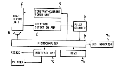
Fig. 2 shows a panel of the control box 3 of Fig. 1, and
Fig. 3 shows the construction of a circuitry associated with
the control box 3.
Referring to Pig. 2, a measurement result display 7a, a
measurement result option-switching switch 7b, a timer-
indicator 7c, switches 7d (an input switch, an input
confirmation switch, a start switch, a reset switch, a ready
switch), a buzzer 8 and so on are mounted on the panel of the
control box 3.
- 16 -
~- 201295~;
The sub~ect operates the panel to set input parameters, and
performs the pedaling at full power for 4 to 5 seconds, see~ng
a pedaling start display and a timer indication. Then, the
sub~ect recognizes the measurement results through the display
or a printed sheet.
In Fig. 3, rotation detection pulses are fed from the load
device unit 2 to a pulse counter 5 via a detection amplifier 4
where the input pulses for each sampling interval are counted,
and the counter feeds to a microcomputer 6 digital data
corresponding to the rotational speed of the pedal la. The
inputs from the various switches 7b are also supplied to the
microcomputer 6 through key operation, and in accordance with
these inputs, computation or processing shown in a flow chart
of Fig. 8 is carried out, and the measurement results of the
instantaneous power are displayed in the measurement result
display 7a. The microcomputer 6 also supplies a brake torque-
controlling analog signal to a constant-current power unit 9 so
as to control the load device unit 2. Further, the
microcomputer 6 is connected to a host computer via an
interface circuit 10, so that the management of the measurement
results, etc., can be made.
G. Flow of O~eration
Next, the operation of the construction of Fig. 3 will now
be described with reference to Fig. 8. A summary of the steps
of Fig. 8 are as follows:
- 17 -
;~()1295~S
Sl: Start
S2: Press start key
S3: Generate start sound
S4: Apply ramp load for 4 to 5 sec. from Lo to 1~
S5: Full-power pedaling simultaneous with start sound
S6: Measure rpm of pedal each 10 msec.
S7: Generate finish sound after 4 to 5 sec.
S8: Move Nk' 5 points five times for averaging to obtain Nk5
S9: Differentiate Nk5 at 50 msec into Mk5
S10 Mk5 = 10 Mk5
Sll: Recognize peak value of increment ~No Of Nk5 by
initial pedaling and determine k as to
S12: Recognize M'max and M'min of Mk at k = to to 448
S13: Filter to prevent double check of M max and M~n
S14: Determine Np point of start of increase of Nk' and
N9~ point of end of this increase, using M max and
M'min
S15: Determine ~NI and ~t
S16: Determine average pedal rpm aN~
S17: Determine linear regression of ~N, ~t by calculating
aNI with respect to ~Nl and ~tl at ~ = 1 to n
S18: Determine ~N, ~t by arbitrary aN using regression
formula and calculate aN, ~t, AN, J.
Sl9: Determine ~P by calculating ~N, ~t determined by the
regression formula used to arbitrary aN, ~N, and J
-- 20~2956
S20: Find WL when rpm corresponding to Nmax is reached
S21: Calculate brake power P0
S22: Calculate maximum power Pmax = P0 + ~Pmax and
determine Nmax, tmax
S23: Appraisal value is given by V = Pmax~weight
S24: Determine average power P from the average of P0~ and
the average of ~.
StePs Sl to S6
In these steps, the subject performs the pedaling at full
power for 4 to 5 seconds, and the rotational speed of the pedal
la during that time is measured at sampling intervals of 10
milliseconds. In this example, a brake load WL is a ramp load,
and varies as follows:
90 ( L~ - Lo) i
WL tkgm] = Lo + ~Zl
where i increments each 50 millisecond in the range of 1 to
90, and Lo and Ih are 1 kgm and 4 kgm, respectively.
Nl~ in Step S6 is the measurement value at each 10
millisecond interval, and k increments each 10 millisecond in
the range of l to 450.
Step S8
This Step deals with the noise elimination process, and the
nth average process N~ is executed in the following manner:
~ 2
N~ -2 N~)
-- 19 --
.. .. . . . . . .
- 201295~i
where k = 3 to 448, n = 1 to 4.
StePs S9 to S10
In these Steps, differentiating processes are carried out.
The differentiation is carried out according to M~ = N~+5 - N~,
and in order to bring this into the same recognition level as
N~, the amplification is carried out according to M~ = 10 M~.
Step Sll
The initial time to is determined. The differential value
M at the time of the start of the pedaling includes many noises
and cannot be recognized, and therefore the following is
provided:
-0.5 ~ N5~ - N5~ ~ 0.5
With respect to k in the case of ~ = 0 to 4, k is
determined as to when N5~lo - N5~ < -1 is established with
respect to k provided by previous condition.
Ste~s S12 to S13
The maximum and the minimum of the differential value are
recognized. In Step S12, with respect to R = to to 448, ~ is
determined as the first minimal value Mlmin = M5~ when ~ ~ M5~L
is established with respect to ~ = -2 to +2, and k obtained at
this time is determined as tl.
~ he second minimal value M2min is found with respect to
k = tl to 448, and similarly n minimal values ~'min (S = l:to
n~ are found.
- 20 -
2(~95~j
With respect to k = to to 448, M5~ i8 determined as the
first maximal value Mlmax = M5~ when M5~ > M5~ i8 established
with respect to L = -2 to +2, and k obtained at this time i8
determined as tl.
The second maximal value M~ax is found with respect to
k = tl to 448, and similarly n' maximal values M-max (S = 1 to
n') are found.
In the checking of the maximal value in Step S13, first,
N5~ at M-max is obtained, and N5~l at M-+lmax is obtained. And,
N'~lmax, obtained when -1 ~ N5~l - N5~ < 1 is obtained with
respect to S = 1 to n, is removed as a recognition mistake.
Similarly, the check with the minimal values are carried
out with respect to n' N-mins.
Ste~_S14
Here, first, the times of the maximal value and the minimal
value are found.
k at Mlmin is determined at kl.
k at M~nax is determined at k2.
k at M2min is determined at k3.
.....
.....
....
k at ND~Imin is determined as k5~n~
k at M~~lmax is determined as k3~l) 12-
k at MDmin is determined as k3~ 3.
- 21 -
-- 201295~;
However,
M'min ..... S = 1 to n.
M-max ..... S = 1 to n'.
Thereafter, using these times, inflection points tl and t2
shown in Fig. 5 are found. These are substituted at the
following mid points, respectively.
klmin = -- tk3t~ l~+2 - k3~l-l)+l] + k3tl-l)~l
k~ax = - [k3~l)+3 - k3~l)+2] + k3~ 2
where Q = 1 to n.
Then, the peak value and the bottom value of the rotational
speed of the pedal la are determined as follows:
NB~ = Nl . k~min ... The value of Nl at time k~min.
Nr~ = Nl . k~max ... The value of Nl at time k~ax
Step S15
Here, the following calculation is made:
= Np~ - NB1
~t~ = (R~_ - R~) 10
lOOO~
where Q = 1 to n.
Ste~ S16
Here, the following calculation is made:
aN~ = Nl-R.~ ... The value of Nl at time k~
k.~ =--(R~ K~) + Rl~
- 22 -
., . .......... . -
~,
' ~,
-:' ' '
2Ql;~35~;
steP S17
The following is calculated:
~N = bl aN + bo
~t = cl aN + cO
steP S18
The inertia power is calculated as follows:
2~ ~N
~P = 1.027 x aN x J
at
Ste~ S19
The processing here is as shown in the block diagram.
Step S20
The following calculation is made, using k at N~' = N~ as
k~:
ky~ Lo)-i
WL = Lo +~
Step S21
The followinq is calculated:
PO = 1.027 WL x N~
Step S22
The following is calculated:
t,, = 10~ K~
In the block diagram, the maximum rotational speed when P~
is obtained is indicated as N~, and the time when P~:is
obtained is indicated as t~.
- 23 -
Z0~ ~9~6
Step S?.3
Here, according to the power theory, the power ~8
proportional to the body weight, and therefore the P~ is
divided by the body weight of each subject as shown in the
block diagram, thereby obtaining a relative appraisal value.
Ste S24
Here, PO, that is, the average of each plo at t~, and ~P,
that is, the average of each ~P~ at aN and ~t are found, and
the following is obtained:
_ _
P = PO + ~P (L = 1 to n)
The average P thus obtained is a simplified appraisal power
of the measurement shown in Fig. 7(C).
As described above, according to the present invention, the
instantaneous power can be measured through a full-power
pedaling of a quite short time, and a physical burden.on the
æub~ect is small. In addition, since the appraisal i8 based on
the peak value obtained around 2 seconds after the start of the
pedaling, this is the optimum appraisal for the instantaneous
power. Further, by using the regression formula, a more stable
and highly accurate appraisal can be made. Since the bicycle
ergometer is utilized, the subject can easily make the.
measurement, and there is no problem from the viewpoint of
safety. Because of the analogousness to a running motion, thi~
is used for substitution for the instantaneous power in the
- 24 -
Z01295~
running motion. Further, by ad~usting the brake torqus, the
measurement can be performed in a wide ~ariety of forms.
- 25 -