Note: Descriptions are shown in the official language in which they were submitted.
-1- 20~3019
FLUID FLOW CONTROL APPARATUS
The present invention relates generally to fluid flow
control and, more particularly it relates to a device for
controlling the flow of fluid out of a fluid collection
reservoir. The device is especially suitable for use in
the control of the outflow of blood from a blood collection
and transfer reservoir.
There have been introduced into the marketplace a
number of direct whole blood cardiotomy reservoirs and
methods for using reservoirs during the recovery and
collection of blood for subsequent return to a patient.
Typically, a system might utilize a negative pressure
source for blood delivery and collection in a reservoir and
use the force of gravity for return of the collected blood
to the patient. Alternatively, instead of using gravity
for blood return, for example, a roller pump or an
intravenous pump might be used for reinfusion of collected
blood to increase the rate of blood return to the patient.
Another technique might be the delivery (under positive
pressure) to the patient of blood previously collected from
the patient or delivery (also under positive pressure) to
the patient of donor blood. In each system, extreme
caution must be exercised to prevent the inroduction of air
into the patient return or delivery line, the presence of
which could create an air embolism endangering the patient.
Disclosure of a blood collection and delivery
apparatus can be found in U.S. Patent No. 3,896,733. In
this device, there is employed in each of two blood
collection chambers a float valve which moves with the
level of blood fluid in the chamber. The operation of the
float valve is governed solely by the rise and fall of the
level of blood in the chamber. Specifically, when the
fluid in the chamber drops to the level of the valve seat
at the bottom of the chamber, the valve sinks into sealing
engagement with the valve seat to close off the fluid
outlet from the chamber. The valve, which takes the form
of a floating disc, is designed to prevent air from
ZOl;~ 9
2--
entering the chamber outlet. When fluid is again
introduced into the chamber, the float valve is designed to
rise with the rising fluid level.
A primary disadvantage of the aforementioned fluid
outflow control system is that, should the floating disc
not be properly seated, then air could enter the chamber
outlet line leading to the patient. Improper seating could
result should the floating disc become tilted or askew, for
example, perhaps resulting from material buildup on the
valve seat, material buildup on the blood surface or
material buildup along the chamber wall. Coagulating blood
could also cause disc tilting and result in an improper
outlet seal. Due to the complex nature and makeup of
blood, one or more of these undesirable situations could
lS occur and result in air passage into the patient line,
particularly when the floating valve depends solely upon
the fluid level and incorporates no additional feature to
positively urge the valve into sealing engagement with the
valve seat.
The primary objective of the present invention is to
advance the art field by providing a reliable reservoir
fluid outlet control device, particularly a device suitable
for controlling blood outflow from a blood collection
reservoir, for releasably sealing the reservoir outlet
against fluid passage therethrough. Accordingly, herein
disclosed is a reservoir outlet control device which is
especially designed and configured to provide a positive
force for urging the outlet control device into a fluid
sealing position at a predetermined fluid level in the
reservoir and for preventing air entry into the patient
delivery line.
The present invention is directed toward a reservoir
outlet control device for controlling fluid flow from a
reservoir outlet port comprising a member being movable
responsive to a level of fluid in the reservoir, means for
releasably sealing the outlet port against fluid flow,
means for releasing the outlet port seal, and means for
first maintaining an open outlet port above a predetermined
_3- Z~13(319
level of fluid in the reservoir and then for reestablishing
the outlet port seal. The device might further include
biasing means for urging the sealing means toward a
reservoir outlet port sealing position. The reservoir
fluid might be blood, might at least be partially blood, or
might be any liquid for delivery to a living body.
Furthermore, the fluid leaving the reservoir might be
pressurized. The member might be a float and the sealing
means might further include an arm. The sealing means
might comprise a self aligning seal which could take the
form of a cup-shaped suction disc. In one embodiment, the
arm might be a resilient member. In another embodiment,
the arm might further include means for preventing movement
of the arm when the fluid in the reservoir is below a
predetermined level.
Also included to be within the scope of the invention,
in one embodiment, is an oulet control device for control-
ling the flow of blood from a blood collecting and delivery
reservoir comprising float means being movable responsive
to a level of blood in the reservoir, lever means including
means for sealing the reservoir outlet against blood flow
therethrough, means for displacing the lever means to a
position releasing the reservoir outlet seal, and means for
holding the lever means in the seal releasing position
until a predetermined level of blood remains in the
reservoir and thereafter freeing the lever means for
reestablishing the outlet seal. The lever means might be a
resilient member. The float means and the lever means
coperatively engage one another until the predetermined
level of blood remains in the reservoir, below which level,
the float means and the lever means disengage to restore
the seal. The device might further include means for
preventing displacement of the lever means when the blood
is below the predetermined level. The device further
includes means for activating the lever displacing means
and means for returning the lever displacing means to a
preactivating position. The lever displacing means might
be a pawl adapted to engage a tab on the lever means.
Z~3~)~9
--4--
Additionally, there might be included means for guiding the
movement of the pawl and means for disengaging the pawl and
the tab. The blood leaving the reservoir might be pressur-
ized and the sealing means might comprise a self aligning
seal, such as a cup-shaped suction disc. Lastly, the
device might further include biasing means for urging the
lever means toward a reservoir outlet sealing position.
The invention further embodies a blood collection
reservoir comprising a housing having an inlet, a collec-
tion chamber and an outlet, and means for controlling theflow of blood through the outlet, the flow control means
comprising float means being movable responsive to a level
of blood in the reservoir, lever means including means for
sealing the reservoir outlet against blood flow there-
through, means for displacing the lever means to a positionreleasing the reservoir outlet seal, and means for holding
the lever means in the seal releasing position until a
predetermined level of blood remains in the reservoir and
thereafter freeing the lever means for reestablishing the
outlet seal. The lever means might preferably be a
resilient member. The reservoir might further include
biasing means for urging the lever means toward a reservoir
outlet sealing position.
FIG. 1 is a partial sectional view of a blood collec-
tion reservoir illustrating, in accordance with theprinciples of the present invention, structural detail of
the reservoir blood outlet section and blood flow control
device in an inoperative or at rest position with the port
closed and before the introduction of blood to the outlet
port area.
FIGS. 2-5 are views similar to the view depicted in
FIG. 1 but sequentially showing the control device in
operation with the introduction of blood to the outlet port
(FIG. 2) and the flow of blood through the outlet port
(FIGS. 3-5).
FIG. 6 is a view substantially as shown in FIG. 1 but
with a level of blood remaining above the reservoir outlet
2~ 3~9
--5--
port after the flow of blood therethrough and after the
outlet port has been sealed.
FIG. 7 is a view similar to FIG. 4 and depicts another
embodiment of the reservoir blood outlet control device.
FIGS. 8-11 schematically depict enlarged views of the
operation of the structure designed to open the outlet port
seal.
The description herein presented refers to the
accompanying drawings in which like reference numerals
refer to like parts throughout the several views. First,
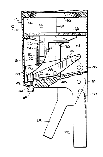
turning to FIG.1, there is illustrated a partial sectional
view of a multicompartmental blood collection reservoir 10
having housing wall 12, blood transfer chamber 14 and an
outlet control device generally designated as 16.
Reservoir 10 is shown as it would appear prior to usage.
There is a compartment above chamber 14 from whence
collected blood is transferred to chamber 14. It should be
understood that, while the term blood is herein used, the
collected fluid could, for example, be substantially whole
blood or at least partially whole blood. Furthermore, the
fluid could include saline, irrigation fluid, heparin or
other fluids associated with surgical procedures. The
fluids which leave the reservoir are suitable for ultimate
delivery to a living body. It should be understood that,
while a multicompartmental blood collection reservoir will
be described, a reservoir having one compartment would be
suitable for the collection of blood and other fluids.
Likewise, reservoir 10 is suitable for handling fluids
other than blood. Reservoir 10 further includes outlet 18,
valve 20, seal ring 22, rod 24, blood filter 26, trigger
28, spring 30 and handle 32. Trigger 28 is pivotally
connected to reservoir 10 by pin 29 and further engages rod
24 at a location not herein shown. A compression spring or
the like (not shown) could be used in place of the spring
configuration designated 30. The spring is designed to
return trigger 28 to its preactivation position.
Outlet control device 16 has a number of interrelated
components. A first component is float 34 which is
- -6- Z~13~
pivotally connected to the reservoir by pin 36. The next
component is lever 38 which is pivotally connected to the
reservoir by pin 40, with lever 38 including valve 42
configured to engage outlet 18 to seal the outlet at a
valve seat generally designated as 44. Lever 38 further
includes projecting post or tab 46. Another component
includes actuator 48, which is connected to rod 24, with
the actuator further engaging pawl 50 via pin 51. A pin 52
connects pawl 50, with pin 52 shown as being located in
member 53 having slot 54, and it is the cooperative action
of pin 52 and slot 54 which guides the movement of the
pawl. Lastly, there is spring 56 which engages lever 38 to
bias the lever toward a reservoir outlet sealing position.
Float 34 further includes a surface 49 which, in FIG. 1, is
shown positioned to stop the downward movement of actuator
48. Surface 49 is designed to obstruct a continued move-
ment of actuator 48 when the surface and actuator engage
one another. Thus, without a predetermined level of fluid
in reservoir chamber 14, the outlet seal cannot be
inadvertently broken.
Turning now to FIGS. 2 through 5, there are shown,
sequentially, views of the reservoir and outlet control
device in operation. A person, placing handle 32 in the
palm of a hand and with fingers extending around trigger
28, could exert a force F on trigger 28 and cause
displacement of the trigger as shown in FIG. 2. This
displacement of trigger 28, pivoting about pin 29, causes
compression of spring 30 (not shown in this view) and the
downward movement of rod 24, valve 20, actuator 48 and pawl
50. As the seal between valve 20 and seal ring 22 is
broken, blood B (or other fluid) is allowed to enter
chamber 14 from a compartment above chamber 14 where blood
had previously been collected. The blood being collected
in chamber 14 rises and causes float 34 to rotate and rise
accordingly. The rotation of float 34 causes surface 49 to
rotate to a position wherein surface 49 will no longer
obstruct the downward movement of actuator 48. There is
now a clearance between the rightmost end portion of
_7_ 2~ 30 1 9
actuator 48 and surface 49. Pawl 50 engages tab 46 on
lever 38 but, in this view, as yet the lever remains
stationary. Outlet 18 remains sealed as valve 42 remains
seated on valve seat 44. Spring 56 biases lever 38 and
valve 42 toward an outlet closing position. No blood flows
through outlet 18. Valve 42 is herein shown as a stopper
but, preferably, it could take the configuration of a
cup-shaped suction disc which would present a seal having a
self aligning feature.
Turning next to FIG. 3, upon release of force F
compressed spring 30 (not shown) urges trigger 28, rod 24,
valve 20, actuator 38 and pawl 50 to return their original
positions shown in FIG. 1. The seal between valve 20 and
seal ring 22 has been reestablished to block the further
inflow of blood into chamber 14. Float 34 has further
risen as the level of blood in chamber 14 has increased.
Also the seal between valve 42 and seat 44 has been broken
to allow blood to flow out of chamber 14 through outlet 18
for delivery to a patient or to another storage
compartment. The upward movement of actuator 48 and pawl
50, the pawl having been engaged with tab 46 as shown in
FIG. 2, first causes the upward displacement of lever 38,
as the lever pivots about pin 40, resulting in the
unsealing of outlet 18. Thereafter, pawl 50 and tab 46
disengage and lever 38, being biased by spring 56, attempts
to return valve 42 to seat 44 to close outlet 18. (The
operation of pawl 50 and lever 38 is shown in greater
detail in FIGS. 8-11). However, float 34 and lever 38, at
end location generally designated as 58, cooperatively
engage one another to prevent lever 38 from returning to
its outlet sealing position. Float 34, being bouyed by the
level of blood in chamber 14, resists the counterclockwise
movement of lever 38 at contact location 58 and the outlet
remains open allowing passage of blood therethrough.
Although not shown in these views, transfer chamber 14
could be pressurized so that the fluid leaving outlet port
18 is under a pressure above atmospheric. A port could be
established in wall 12 and, for example, a sphygmomanometer
_ -8- 201 301 9
bulb, a pressure gauge and tubing communicating with the
port could be used to establish desired pressure levels.
Next, we turn to FIG. 4 and observe that outlet 18
remains open to blood outflow, the level of blood in
chamber 14 has dropped, float 34 has rotated counter-
clockwise responsive to the lowered blood level and that
float 34 and lever 38 remain in contact at location 58 thus
preventing the return of valve 42 to seat 44. FIG. 5 shows
yet the further lowering of the blood level in chamber 14
and that float 34 and lever 38 remain in engagement at
location 58 to keep outlet 18 open. It should be observed
that contact between the float and lever at location 58 is
about to be broken. Lastly, we turn to FIG. 6 and observe
that there is no longer contact between float 34 and lever
38 at location 58 and that lever 38, being biased by spring
56, has further rotated to return valve 42 to seat 44 to
thereby seal outlet 18 against further blood outflow. It
should be observed that a level of blood remains above the
closed outlet port to insure that no air is allowed to pass
through outlet 18. The sequences depicted in FIGS. 2
through 6 can now be repeated.
FIG. 7 shows yet another embodiment of outlet control
device 16. Here the outlet control device has
been designated 16', the float 34', the float pivot pin
36', the lever 38', the tab 46', the surface for
obstructing movement of actuator 48 has been designated
49', and the location wherein float 34' and lever 38'
engage has been designated 58'. Lever 38' is a resilient
member, perhaps a leaf spring or the like, connected to the
reservoir by rivet 60. Operation of outlet control device
16' is substantially as hereinbefore described with respect
to device 16. Movement of actuator 48 and pawl 50 to
engage tab 46' and open outlet port 18 and raise lever 38'
has been completed. Here as the level of blood B drops,
float 34' rotates in a clockwise direction about pivot 36'.
At location 58', triangulated section 62 of float 34' and
triangulated section 64 of resilient member 38' are
slidingly engaged to maintain outlet port 18 open, that is,
- 9 -
lever 38' is releasably held in the position down. As
float 34' continues its clockwise rotation as the blood
level drops, sections 62 and 64 will slide past one another
and lever 38', releaased from its raised position, will
move downwardly and valve 42 will engage valve seat 44 to
seal oulet port 18 against further blood outflow. As
before, a level of fluid will remain above closed outlet
port 18. Thereafter, the fill and discharge cycle of
transfer chamber 14 can begin anew.
FIGS. 8-11 schematically show the operation of the
pawl as it is used to engage and displace the lever arm.
The line of sight is looking basically at the pawl from
right to left. FIG. 8 shows pawl 50 substantially in the
posiion of FIG. 1, that is, at least prior to activation of
the pawl. The downward and outward movement of pawl 50
will be governed by movement of pin 52 traveling along slot
54. FIG. 9 shows the pawl just prior to engagement with
tab 46 and shows, in phantom, the pawl in latching
engagement with tab 46 (as shown in FIG. 2). In FIG. 10,
pawl 50 is in engagement with tab 46 and is about to move
upwardly. Upward movement of pawl 50 latched to tab 46
will cause upward displacement of lever arm 38 and the
opening of outlet port 18. FIG. 11 shows the rocking
motion of pawl 50 and the release of tab 46. Lever 38 will
basically be in the position shown in FIG. 3. Pawl 50 will
continue moving upwardly to return to the position shown in
any of FIGS. 1 and 3-8.
The present invention has been described herein with
specific reference to the preferred embodiments thereof.
~ 30 However, those skilled in the art will understand that
changes may be made in the form of the invention covered by
the claims without departing from the scope and spirit
thereof, and that certain features of the invention may
sometimes be used to an advantage without corresponding use
of the other features.