Note: Descriptions are shown in the official language in which they were submitted.
2~
G-~,405 C-4~42
IGNITION COIL
This invention relates to ignition coils for
developing a spark firing voltage that is applied to a
spark plugs of spark ignited internal combustion
engines.
Ignition coils utilize primary and secondary
windings and a magnetic circuit. The magnetic circuit
may be formed of steel laminations as disclosed in the
U.S. patent to House et al. 4,480,377. That patent
points out that the magnetic circuit has an air gap and
points out that the air gap must be adjusted during
manufacture of the coil.
It has also been suggested in the U.S. patent
to Hause 2,885,458 to provide an ignition coil that has
a circular core that can be formed of iron powder and a
binder, such as a phenolic that is molded to shape.
One of the objects of this invention is to
provide an ignition coil that has a magnetic circuit
that includes one or more air gaps, but wherein the
magnetic circuit is so arranged that the air gaps need
not be adjusted during manufacture of the coil thereby
eliminating the costly adjustment of the air gap in a
manner set forth in the above-referenced House et al.
patent. This is accomplished by providing an ignition
coil where the primary and secondary windings are
disposed about a center core of magnetic material. The
core is in a magnetic circuit with a pair of annular
magnetic parts or pole pieces that have outer
cylindrical surfaces. A cylindrical part of magnetic
material forms a return path for magnetic flux and is
spaced from the outer cylindrical surfaces of the pole
pieces to form an air gap therewith. The
` ' ' ~
2~
cross-sectional area of these air gaps is many times
larger than the cross-sectional area of an air gap like
the gap used in the center leg of the magnetic circuit
of the above-referenced House et al patent. Since coil
inductance is generally related to the ratio of A/L
where A is the cross-sectional area of the total air gap
and where L is the length of the air gap it can be seen
that by making A large, variations in L have little
effect on inductance. Accordingly, this invention makes
A large with the result that L need not be adjusted
during manufacture of the coil to obtain an inductance
that falls within an acceptable range of values.
In regard to providing an ignition coil that
does not require the adjustment of the air gap length L,
the coil of this invention is arranged such that the
portions thereof are formed of a magnetic material that,
in effect, provides many small air gaps. This material
can be a composite material of iron powder particles and
an electrical insulating material. The insulating
material separates the particles and binds them together
and provides many air gaps between the particles that
act like air gaps. During operation of the coil,
magnetic energy is stored in the many gaps of the
composite material and in the air gaps between the pole
pieces and the cylindrical part, that has an air gap
length L. The total magnetic energy that is stored in
the magnetic circuit is the energy stored in the gaps of
the composite material added to the energy stored in the
air gaps that have the length L. The total magnetic
energy that is stored, with the arrangement that has
been described, does not vary substantially with
variations in air gap length L over a certain range.
Another object of this invention is to provide
an ignition coil of the type described where the pole
pieces are formed of a composite iron powder and
:: ,': :~
. .:
2~1~.3~
electrical insulating material where the particles of
powder are coated by the insulating material and wherein
the insulating material serves to insulate the particles
from each other and to bind the particles together.
Still another object of this invention is to
provide an ignition coil where an outer return path for
magnetic flux generated in a core member is provided by
a part that is formed of magnetic material which also
serves as a shield to limit the open-circuit voltage
developed by the secondary winding of the coil. The
part is a cylindrical split shield that is disposed
about the coil windings of a segment-wound secondary
coil. The shield operates to increase the capacitance
of the secondary winding thereby limiting its
open-circuit voltage and also forms a flux return path.
Another object of this invention is to provide
an ignition coil assembly that is complete and testable
prior to being dropped into an outer supporting case.
This allows the same production line to build coils for
many different applications and for differing cases and
terminations of the coil windings.
Still another object of this invention is to
provide an ignition coil where the inductance of the
coil varies as a function of primary winding break
current. The variation in inductance is such that above
a certain magnitude of break current the inductance
decreases with increasing primary winding break current.
In The Drawings:
Figure 1 is a side view with parts broken away
of an ignition coil assembly;
Figure 2 is a sectional view taken along line
2-2 of Figure l;
Figure 3 is a plan view of an ignition coil
assembly made in accordance with this invention;
Figure 4 is an end view of the assembly shown
: - .,
'' -
2~
in Figure 3 looking in the direction of arrows 4-4;
Figure 5 is a sectional view taken along line
5-5 of Figure 4;
Figure 6 is view of the three components that
are used in the iqnition coil assembly shown in Figure
5;
Figure 7 is a sectional view of a magnetic part
taken along line 7-7 of Figure 6;
Figure 8 is a sectional view taken along line
8-8 of Figure 6;
Figure 9 is a sectional view of a modified
ignition coil; and
Figures 10 and 11 are, respectively, end and
lS side views of an ignition coil assembly that is used in
the ignition coil of Figure 9.
Referring now to the drawings, and more
particularly to Figure 1, the reference numeral 20
designates an outer case or housing that is formed of a
plastic insulating material. The housing has walls
defining an internal chamber area that receives two
ignition coil assemblies, each designated as 22 and
shown in dotted lines in Figure 1. The secondary
winding of a given coil assembly is connected to a pair
of male terminals. The secondary winding of the other
coil is connected to another pair of male terminals.
The male terminals have each been designated as 24 and
one of the terminals 24, and associated tower 26, is
shown in Figure 2. Tower 26 is integral with outer case
20.
The case 20 forms an enclosure that is open at
the end designated as 28. In the manufacture of
ignition coils, the coil assembly 22 is made so that it
is a complete unit that is testable prior to being
dropped into case 20 through the open end of the case.
After coil assemblies 22 have been dropped into case 20
~ ~ 3 ~
and electrical connections have been made to terminals,
like terminal 24, a potting compoun~ that is formed of
electrical insulating material is used to fill the
interior of case 20 and to encapsulate the coil
assemblies 22. The potting compound is applied to the
interior of case 20 through its open end. Some of the
potting compound is shown in Figure 1 and designated as
30. It, of course, closes the open end of case 20.
The ignition coil apparatus shown in Figures 1
and 2 iS for a four-cylinder engine and is for a
so-called distributorless ignition system where a given
secondary winding is connected to two spark plugs.
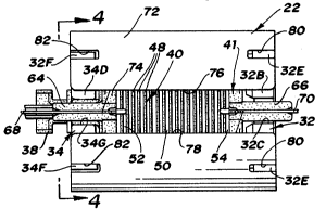
The ignition coil assembly 22 iS shown in
Figures 3-5. The assembly includes two magnetic parts
32 and 34. These parts are formed of composite iron
powder particles and electrical insulating material
which are compacted or molded to the shape shown. The
particles of iron powder are coated with the insulating
material. The insulating material forms gaps, like air
gaps, between the particles and also serves to bind the
particles together. This composite material will be
described in more detail hereinafter.
The magnetic part 32 has an axially extending
core portion 32A that is integral with an end wall
portion 32B. It can be seen in Figure 8 that portion
32B is annular and has a notch 32C. Portion 32B has a
circular outer wall 32D and a plurality of radially
extending lugs or bosses 32E . It can be seen from
Figure 8 that the core portion 32A has a hexagonal
cross-section or outline throughout its length.
The hexagonal core portion 32A fits into a
hexagonal bore 34A formed in an axially extending core
portion 34B of part 34. Figures 6 and 7 illustrate part
34 in detail. A portion of the hexagonal bore 34A is
provided with six axially extending ribs each designated
s
2~.3~
as 34C. Part 34 has an annular end wall portion 34D
that is integral with portion 34B and it has an outer
circular surface 34E. Part 34 further has lugs 34F and
a notch 34G.
The dimensions of core portion 32A and bore 34A
are such that walls of the parts engage each other when
hexagonal part 32A iS inserted into hexagonal bore 34A.
However, when parts 32 and 34 are assembled to each
other, there is an interference fit between ribs 34C and
an end portion of core portion 32A. This interference
fit secures parts 32 and 34 to each other. It will be
appreciated that when portion 32A iS assembled into bore
34A, the end face of tubular portion 34B will engage or
bottom out against a surface of portion 32B.
The ignition coil has a primary winding 36
which is formed of insulated wire, the inner turns of
which are wound directly on the outer cylindrical
surface 34E of core portion 34B. This primary winding
may be comprised of two winding layers each being
comprised of sixty-two turns of No. 23 AWG wire. Since
the primary winding 36 is wound directly on the outer
surface 34H of portion 34B, heat generated in winding 36
is transferred to portion 34B which acts as a heat
radiator.
In the manufacture of the ignition coil, the
part 34 and the primary winding 36 form a primary
winding unit or assembly that is manufactured and
subsequently assembled to other parts of the coil in a
manner that will be described. To make the primary
winding unit, primary winding 36 iS wound on portion
34B. The end leads of the primary winding 36, after
winding, are supported by an insulator 38 that is
supported in the notch 34G.
The ignition coil has a secondary winding unit
that is disposed about the primary winding 36, which is
'
:
3~
generally designated as 40. $his unit is shown in
Figures 5 and 6. This unit comprises a one-piece spool
41 that is formed from a molded plastic insulating
material. This spool has inclined portions 42 and 44
which carry a plurality of axially spaced and
circumferential extending ribs each designated as 48.
The ribs 48 and surfaces of portions 42 and 44 define a
plurality of axially spaced winding slots each of which
contains a coil winding. There are nineteen slots and
nineteen axially spaced coil windings shown in Figure 5.
The coil winding in the center of the coil spool has
been designated as 50 and the coil windings at each end
of the spool have been designated respectively as 52 and
54. Coil winding 50 has more turns than either coil
windings 52 and 54 and as one progresses from coil
windings 52 or 54 toward center winding 50, the number
of turns of a coil winding increases. By way of
example, coil 50 may be comprised of 780 turns of No. 42
AWG wire whereas coil windings 52 and 54 may each be
comprised of 318 turns of this wire. As one goes from
either coil 52 or 54 toward center coil 50 the number of
turns for each successive coil winding may be 480, 517,
556, 593, 630, 667, 706 and 743 turns. Thus, the two
coils at either side of coil 50 will have 743 turns. It
will be appreciated that all nineteen coils are
connected in series by cross-over connections that
extend through slots in ribs 48. It will also be
appreciated that the secondary winding is what is known
as a segment-wound coil since it is made up of a
plurality of axially spaced winding segments.
The coil spool 41 for secondary unit 40 has end
walls that carry a plurality of circumferentially spaced
integral spokes or arms 56 at one end thereof and spokes
or arms 58 at the other end thereof. Spokes 56 each
have tang or spacer portion 60 that extend axially of
. . ~
Z~ 3~ r
the coil spool. In a similar fashion, arms 58 have
axially extending tang or spacer portions 62.
The coil spool has integral terminal retainer
portions 64 and 66 that support terminals 68 and 70 that
are electrically connected to opposite ends of the
secondary winding. The circumferential spacing of tangs
60 is shown in Figure 4 and tangs 62 have the same
spacing.
Disposed about secondary winding unit 40 is a
part 72 that is formed of a magnetic material such as
galvanized steel which may have a thickness of about
1.20mm. The part 72 is shown in Figures 3-5 and as will
be more fully described, it operates to provide a flux
path for flux developed by primary coil 36 and as a
shield. The part 72 has a circular shape, as can be
seen in Figure 4, and it is split to provide a gap 74
between edges 76 and 78 of part 72. The part 72 has
three circumferentially spaced slots 80 at one end
thereof and three circumferentially spaced slots 82 at
the opposite end thereof. Part 72 may further have some
openings (not illustrated) that allow potting compound
to pass into the interior of part 72.
It can be seen in Figure 5 that the tangs or
spacers 60 serve to space an inner surface of part 72
from circular surface 34E of magnetic part 34. In this
regard, outer surfaces of tangs 60 engage inner surfaces
of part 72 and inner surfaces of tangs 60 engage outer
circular surface 34E. This forms one radial air gap for
the magnetic circuit of the ignition coil which is
designated as 86. This air gap is between surface 34E
and the portion or area of part 72 that is aligned with
surface 34E. The tangs 62 perform the same function as
tangs 60, that is, they provide another radial air gap
87, like air gap 86, that is between an inner surface of
part 72 and circular surface 32D of part 32. In this
2~ P~
regard, tangs 62 have the same thickness and
circumferential spacing as tangs 60. Tangs 60 and 62
may be about 1.0 mm thick so that the radial length of
S radial air gaps 86 and 87 is about l.Omm.
The part 72 may be about 1.2mm. thick and have
a length of about 57mm. The inner radius of part 72 may
be about 21mm. and the width of gap 74 can be about
12mm.
Before proceeding with a further description of
this invention, it will be helpful to explain the
assembly steps that are used to assemble the coil.
Assume that a primary unit is available, that is, a
unit that is comprised of part 34 with the primary
winding 36 wound thereon. The secondary assembly 40 is
now assembled to the primary winding unit. When doing
this, a pair of radially extending locator lugs 90
(Figure 4) that are integral with the left end of coil
spool 41 are inserted into radially extending recesses
92 (Figure 7) or slots formed in the inner face of
portion 34D of part 34. The tangs 60 are axially
slipped over annular surface 34E. The shield 72 is now
assembled by sliding it over secondary assembly 40. In
doing this, the lugs 34F slide into the slots 82 of
shield 72. During assembly of shield 72, it is sprung
apart slightly so that it can clear tangs 60 and after
assembly the part 72 springs back into engagement with
outer surfaces of tangs 60. With the parts assemblèd as
has been described, the final step is to assemble part
32. This is accomplished by inserting portion 32A of
part 32 through secondary unit 40 and into the bore 34A
of part 34. When doing this, lugs 32E slide into slots
80 and the left end of portion 32A slides into the area
of bore 34A that has the ribs 34C. In the final
assembled position of part 32, there is a press or
interference fit between ribs 34C and the end of core
'
' .
portion 32A that prevents axial separation of parts 32
and 34. Further, the width of slots 80 relative to the
width of lugs 32E is such that there is a press fit
between lugs 32E and the surfaces of slots 80 that
engage the lugs. This prevents axial movement of shield
72 relative to part 32 and provides an electrical
connection between parts 72 and 32.
It is noted that parts 32 and 34 have been
shown and described as each having three lugs 32E and
34F. In order to simplify the assembly, the parts 32
and 34 can be arranged so each part has only one lug.
In such an arrangement, the lug 32E opposite notch 32C
and the lug 34F opposite the notch 34G would be used and
the other two lugs on each part eliminated. Shield 72
would now have only two slots, one at each end thereof
positioned to receive the lugs.
It will be appreciated that when the coil has
been assembled, as has been described, a complete unit
has been made which is testable prior to being inserted
as a unit into a case.
Referring now to Figure 9-11, a modified
ignition coil is illustrated. This coil differs from
the one that has been described in that, among other
things, the magnetic circuit has been modified and the
coil uses two shields instead of the single shield 72.
In Figure 9, reference numeral 100 designates
an open-ended case 100 that is formed of electrical
insulating material. Disposed within the case is an
ignition coil assembly generally designated as 102.
This assembly is inserted into case 100 and a potting
compound is then used to fill the case and encapsulate
the assembly 102. A portion of this potting compound is
shown a~d designated as 104.
The coil assembly 102 is comprised of magnetic
parts 106 and 108 which are formed of the same composite
2~3~Z~k
material as parts 32 and 34. Part 108 has an annular
portion 110 that has a circular outer surface or wall
112. Further, part 108 has an axially extending core
portion 114 that has a bore 116 that is square in
cross-section as shown in Figure 10. The outer surface
of core portion 114 is circular and wound thereon is a
primary winding 118. Part 108 has a bar portion 120
(Figure 10) that extends across the open end of bore
116.
Part 106 has an annular or circular outer
surface or wall 122 and a bore 124 that is square in
cross-section.
A magnetic core member 126, which is square in
cross-section, is located in bore 116. The opposite
ends of core 126 are located in corresponding square
bore portions of parts 106 and 108 with the end of core
126 engaging bar 120. Core 126 is comprised of a stack
or plurality of steel laminations as shown.
The ignition coil assembly has a secondary
winding assembly 128 which is like previously described
secondary winding 40. This winding is of the segment
wound type and has a coil spool 130 formed of insulating
material that carries the segment windings. The spool
130 has a plurality of circumferentially spaced tangs
132 at one end thereof and another plurality of
circumferentially spaced tangs 134 at the opposite end
thereof. There may be eight tangs on each end of the
coil spool.
3~ The ignition coil of the Figure 9-11 embodiment
uses two steel shields 136 and 138 instead of a single
shield 72. These shields have an arcuate or
semi-circular shape as can be seen in Figure 10. The
shields-can be formed of a magnetic material such as
galvanized steel having a thickness of about 1.20mm.
Each shield has a pair of bent or struck radially
11
'
;, '. ` . : ~ ''
'~
Z Q ~ ,
12
inwardly extending integral tabs located at opposite
ends thereof. The tabs on shield 136 are each
designated as 140 and the tabs on shield 138 are each
designated as 142.
The shields are assembled to magnetic parts 106
and 108 by inserting the tabs into radially extending
recesses formed respectively in the outer end surfaces
of parts 106 and 108. Thus, tabs 140 of shield 136 are
inserted radially into recesses or grooves 144 and 146
formed respectively in parts 106 and 108. In a similar
fashion, tabs 142 on shield 138 are inserted into
corresponding recesses in parts 106 and 108. One of
these recesses is shown in Figure 10 and identified as
150. The tabs can be sprung apart when a pair of tabs
is inserted so that after insertion they exert a
clamping force on parts 106 and 108 to thereby hold
parts ln6 and 108 engaged and to thereafter prevent
axial separation of these two parts.
When the shields 136 and 138 are assembled,
inner surfaces thereof engage outer surfaces of coil
spool tangs 132 and 134. These tangs engage the shields
and the inner surfaces of these tangs engage
respectively portions of cylindrical surfaces 112 and
122.
In the final assembled position of shields 136
and 138, they are separated by two axially extending
gaps 152 and 154. Further, coil spool tangs 132 and 134
serve to space shields 136 and 138 from surfaces 112 and
122 to form radial air gaps between the shields and
surfaces. The tangs may be about l.Omm. thick so that
the radial air gap is also about l.Omm.
The following describes another modified
magnetic circuit that is not illustrated in the
drawings. In this modification, the magnetic circuit is
comprised of two axially spaced magnetic parts each of
12
2~,
13
which is like part 106 which are formed of the same type
of material as parts 32 and 34. These parts are joined
by an axially extending one-piece solid core member that
has no internal bore and which carries a primary winding
like primary winding 118. This part is formed of the
same material as parts 32 and 34. The one-piece core
member is cylindrical except for two end portions which
are both square in cross section. The primary coil is
wound on the cylindrical portion. The square
end-portions are press-fitted into corresponding square
openings in the two axially spaced magnetic parts. The
square-end portions have a diameter that is less than
the diameter of the cylindrical portion to provide
opposed radially extending walls that respectively abut
inner radial surfaces of the two magnetic of the two
magnetic parts when the core member is assembled to the
parts.
As has been described, various parts of the
ignition coils are formed of a composite material of
iron particles carried by a binder of electrical
insulating material. The iron particles may have a mean
particle size of about 0.004 inches. In production of a
part, the iron particles are coated with a liquid
thermoplastic material which encapsulates the individual
particles. The coated iron particles are then placed in
a heated mold or press where the composite material is
compression molded to the desired shape or density. The
final molded part is then comprised of iron particles in
a binder of cured thermoplastic material. By way of
example, the final molded part may be, by weight, about
99% iron particles and 1% plastic material. ~y volume,
the part may be about 96% iron particles and 4~ plastic
material.
In the final molded part, the cured
thermoplastic material binds the iron particles together
13
2~3~
14
and it also electrically insulates most of the particles
from each other. Some of the particles may be engaged
with no electrical insulation between them. However,
for the most part, all of the particles are insulated
from each other to provide a large number of qaps
between particles that are of cured thermoplastic
material. These gaps are like air gaps since the
thermoplastic material has about the same permeability
as air. Consequently, the composite material in effect
produces a part that has in effect a multiplicity of
minute air gaps. ~ecause of this, the composite
material is capable of storing magnetic energy in the
gaps in a manner that is described hereinafter.
The following explains the operation and
features of the ignition coil of this invention. With
respect to the embodiment of Figures 1-8 when primary
winding 36 is energized, magnetic flux is developed in
the core comprised of telescoped core portions 32A and
34B. This flux passes into annular portion 34D and then
across air gap 86 to cylindrical steel part 72. Flux
now passes axially through part 72 and then through air
gap 87 to annular portion 32B. It can be seen that the
part 72 forms a low reluctance flux return path for the
flux developed in the core. Further, it is evident that
this flux passes radially through the air gaps 86 and
87. When the primary winding is deenergized, a large
spark plug firing voltage is induced in the secondary
winding of secondary assembly 40.
The air gaps 86 and 87 have a radial length of
about 1.0 mm and the cross-sectional area of the air
gaps is large as compared to conventional ignition coil
air gaps that are in the coil core. This, assuming that
the length of the surface 32D is about 7mm., that the
diameter of cylindrical surface 32D is about 40mm. and
that notch 32C is about 35 degrees wide the air gap area
14
2~.3~
of gap 87, excluding the notch, is about 2 x 3.14 x 20 x
325/360 x 7 or about 793 6q. mm. The air gap 86 has
about the same area as the area of air gap 87. It,
S therefore, can be seen that the ratio of air gap length
area A to air gap length L or A/L, which is a factor
that determines coil inductance, will not vary much if
the air gap length L varies during manufacture of the
coil. Accordingly, the air gap length L can be held
well within certain tolerances without adjusting it
during the manufacture of the coil.
Further, by-using a composite iron powder and
insulating material for parts 32 and 34, the gaps
between the particles of the composite material stores
magnetic energy in addition to magnetic energy that is
stored in air gaps 86 and 87. The total stored energy
is related to the sum of the energy stored in parts 32
and 34 and the energy stored in air gaps 86 and 87. If
the length of the air gaps 86 and 87 is decreased, the
volume of these air gaps decreases, causing an increase
in flux level due to an increase in inductance. The
energy stored in these air gaps 86 and 87 decreases due
to the decrease air gap volume. However, since the
volume of the air gaps in the composite material of
parts 32 and 34 has not changed, it will store more
energy due to the increased amount of flux and cancel
out most of the effect of the energy lost in the air
gaps 86 and 87. The use of composite material for parts
32 and 34, therefore, further reduces the effect of
variation in the air gap length L and is, therefore,
self compensating. Putting it another way, the total
magnetic energy stored in the magnetic circuit of the
coil will not vary substantially for variations in air
gap length L within a certain range.
The part 72 forms a low reluctance path for
magnetic flux and it also provides a shield which has
~ ~.3
16
the effect of increasing the capacitance of the
secondary winding. Thus, segment wound secondary
windings have an inherent capacitance that is so low
S that under a open circuit condition, that is, where the
secondary winding is not connected to a spark plug,
extremely high secondary voltages of the order of
60-80KV may be developed. These high secondary
voltages induce high primary winding voltages which may
cause failure of the electronic output device that is
connected to the primary winding to switch primary
winding current on and off. The part 72 increases the
capacitance of the secondary winding such that primary
peak reflected voltage can be limited to about 500
volts. This protects the electronic output device so
that a clamping circuit for the electronic device is not
required. The capacitance of the secondary winding is
increased since there is capacitance between the
secondary winding and part 72. The part 72 must be
split and this is accomplished by the split or gap 74.
The reason for the gap or split, is that without a
split, the eddy currents developed in the part 72 would
produce a shorted turn effect, which would decrease the
efficiency of the coil. The use of part 72 as a flux
return path increases the coupling between the primary
and secondary coils as compared to a laminated stack of
a leg of an "E" core. Further, the part 72 reduces the
stray magnetic flux external to the coil structure,
therefore, reducing electromagnetic radiation.
What has been described in regard to part 72
applies to the parts 136 and 138 of the Figure 9-11
embodiment. Thus, parts 136 and 138 perform the same
functions as part 72 and part 72 could be replaced by
two parts like parts 136 and 138 and vice versa. When
using two parts, like parts 136 and 138, there are two
splits or gaps.
16
:- ~
3~
In addition to the functions that have been
described for shield parts 72, and 136 and 138, it is
pointed out that they perform mechanical retaining or
securing functions. Thus, in the embodiment of Figure
9-11 the parts 136 and 138 secure parts 106 and 108
together and in the Figure 1-8 embodiment part 72
performs a similar function.
In the magnetic circuit of the Figure 9-11
embodiment, the core within primary winding 118 is
comprised of the laminated core member 126 and portion
114 of composite magnetic part 108. There are two
parallel flux paths, namely a primary flux path through
laminated core 126 and a secondary flux path through
portion 114 which is parallel with the path through
laminated core 126. The laminated core 126 has a lower
reluctance than the reluctance of portion 114. What has
been described provides an ignition coil that has a
variable incremental inductance that varies as a
function of the magnitude of break current applied to
primary winding 118. Thus, the magnetic core is
optimized for high permeance and high inductance at a
low level of primary current for passage of flux through
laminated core 126 and has a parallel flux path through
portion 114 for a higher level of primary current with
decreased inductance. This is accomplished, without
greatly decreasing the coupling between the primary and
secondary coils, and without saturating the primary flux
path provided by core member 126. The low level of
primary current, that is the current attained when the
primary winding is deenergized (break amps) may be about
6.5 break amps. The higher level may be about 18.5
break amps.
When operating at the lower level of current
(6.5 break amps) the magnetic circuit operates such that
about 7% of the generated flux passes through portion
17
18
114 with 93~ passing through laminated core member 126.
When operating at 18.5 break amps, about 30% of the flux
passes through portion 114 with 70% passing through core
126.
To further explain the variable incremental
inductance feature of this invention, it will be
appreciated that the incremental inductance of the coil
is related to changes in B (flux density) caused by a
change in H ~magnetizing force) of the magnetic circuit
of the coil. The incremental inductance is related to
the change of B divided by the change in H that caused
the change in B or ~B/~H. Thus, if the B-H curve is a
straight line (linear relationship) the incremental
~5 inductance remains substantially constant because a
given change in H produces the same change in B.
The total inductance of the coil is the
inductance related to laminated core 126 added to the
inductance related to core portion 114. The B-H curves
of core 126 and core portion 114 are not the same.
Thus, for a certain lower break current range, the B-H
curve for core 126 is linear so that the inductance
(~B/~H) remains substantially constant over a certain
current range. However, this linear curve is such that
there are relatively large changes in B for given change
in H. The B-H curve for portion 114 also has a linear
portion over a lower current range so that the
inductance related to it remains constant over the
current range. The ratio ~B/~H for portion 114 is less
than the ratio ~B/~H for laminated core 126. As current
goes above a certain level, for example 6.5 break amps,
the B-H curve for portion 114 makes a transition from a
straight line to a non-linear curved portion where the
ratio ~B/~H progressively decreases thereby decreasing
inductance at currents above 6.5 break amps. This
curved non-linear portion curves away from the B axis
18
,~ ., ~ . ' ' ~:
(ordinate) and toward the H axis (abscissa).
From what has been described, it will be
apparent that the ignition coil provides a dual mode
operation. Thus, if the break-amp current is about 6.5
amps, the coil will have a certain fairly constant
inductance that is selected to provide a desired
burn-time for normal ignition system operation.
However, if the break-amp current is increased to, for
example, 18.5 amps the ignition coil will have an
incremental inductance that decreases as current
increases from 6.5 to 18.5 amps. Thus, the inductance
related to core 126 remains constant, but there is a
substantial reduction in incremental inductance provided
by portion 114 with the result that above 6.5
break-amps, the total incremental inductance decreases.
Since inductance decreases as primary current goes from
6.5 to 18.5 amps, that change in current will be a fast
rise (lower inductance) that that the coil will now
deliver a fast rise higher secondary current that is
suitable for firing a fouled plug. Thus, 18.5 amp break
current could be used for cold starting and 6.5
break-amps for normal operation. The coil operates such
that as compared to a conventional coil that is capable
of high secondary currents, the burn-time is not
sacrificed.
The Figure 5 embodiment of the invention also
has a variable inductance that varies with the magnitude
of the applied primary break current. Thus, in Figure 5
the B-H curve for core portions 32A and 34A, which are
formed of composite material, is such that for a certain
range of low primary winding break current, ~B/~H
remains substantially constant to provide a constant
incremental inductance. This range, for example, may be
up to 6.5 amps. If break current is increased to above
6.5 amps, the s-H curve goes from a straight line
19
.
2~fs
(linear~ to a curved portion where ~B/~H decreases with
increasing current thereby providing a decreasing
incremental inductance with increasing current above 6.5
amps. ~ The decreasing inductance with increasing current
effect produced by the Figure 5 embodiment is not as
pronounced as the effect produced by the figure 9-11
embodiment.
As has been described, in connection with the
Figure 1-8 embodiment, magnetic energy is stored in
parts 32 and 34 and in the air gaps 86 and 87. The
embodiment of Figure 9-11 operates in the same manner,
that is, magnetic energy is stored in parts 106 and 108
and in the air gaps between surfaces 112 and 122 and
shields 136 and 138. The total stored magnetic energy
will not vary substantially for variations in the air
gap length for the same reasons that have been set forth
in describing the operation of the Figure 1-8
embodiment. Moreover, the cross sectional area A of the
air gaps is large as compared to air gap radial length L
in the Figure 9-11 embodiment for the same reasons as
has been described in connection with the description of
the Figure 1-8 embodiment. Thus, the ratio A/L for the
Figure 9-11 embodiment can be about the same or slightly
less than the A/L ratio of the Figure 1-8 embodiment.
: :` .......................... !
` ' ' ~ . ' , ~:
' .