Note: Descriptions are shown in the official language in which they were submitted.
CSD zriternational S.V. , Opmeer, the Netherlands ~' ~ ~ ~' ~ ~ ~~
sYSTEM FE7R TFi'E PREVENTION OF PIRB, wz~x~ ~R t~xar~) c~,s .ANn
TAE x.xxs ~ttoM ~topAC.~TIrrc uaox~ ~s~s
The invention relates to a system for the prevention of
fire, water or (flue) gas and the like from propagating
along cables as well as to a safety chute arid a sealing
body manifestly suited to be used in~the system. Such
cables rnay, for instance, be electric cables.
A system in which cables have been disposed in a lead-
through chute is generally known. The known system is
formed by coated mineral-wool plates which may be mounted
around the lead-through chute in, for example, a lead-in
aperture in a wall.
One drawback of the known system is that in actual
practice it is often very difficult to mount these
mineral-wool plates from the outside in the lead-in
aperture, around the lead-through chute and round about
the cables passed through the said aperture an account of
their poor accessibility from the outside. A further
drawback is that when additional new cables are inserted
into existing lead-throughs provided with mineral-wool
plates, considerable damage may be inflicted upon these
plates. Moreover, the known system has the disadvantage
that it can hardly, if at all, withstand mechanical loads,
so that in the event of a fire a jet of fire-fighting
water can easily thrust the coated mineral-weal plates cut
of the lead-in aperture.
It is an object of the present invention to provide a
simple and aesthetically justified system for the
prevention of fire, water or (flue) gas and the like from
propagating along sables, which is easy to install for any
size of lead--in aperture, which is capable of withstanding
high mechanical loads and in which additional new cables
can readily and simply be introduced into existing Iead-
throughs.
CA 02013227 1999-10-07
2
Generally speaking the above object is met by the present
invention which provides a safety chute system for the
prevention of fire, water, or gas from propagating along cables
contained in an open top channel-shaped lead-through chute
passing through a wall, the safety chute system comprising
(a) an open top channel-shaped housing positioned in spaced
surrounding relation with the lead-through chute externally of
the wall and with the open top of the lead-through chute facing
outwardly of the open top of the safety chute; (b) at least one
sealing body of fire resisting material removably positioned in
the space between the two chutes; and (c) cover means for
covering the open top of the safety chute to fully enclose the
lead-through chute therein.
One embodiment of a system according to the invention is
characterized in that the sealing body can be installed along at
least a part of the inner wall of the safety chute, whereby an
air insulation clearance is allowed between the sealing body and
the said part of the inner wall of the safety chute by means of
spacers provided on the sealing body. The spacers may consist
of, for instance, ribs or studs. The air insulation clearance
prevents a filler present in the safety chute from being readily
damaged by fire owing to the heat thereby generated.
Another embodiment of a system according to the invention is
characterized in that the sealing body contains at least one
inner cavity. This cavity also forms an air insulation
clearance for the protection, in the event of a fire, of a
filler present in the safety chute.
A further embodiment of a system according to the invention is
characterized in that the system is provided with a filler
substantially made of a fire-resisting material which can be
applied in the safety chute. This filler serves to impart
sufficient "density" to the interior of the safety chute such
that fire, water or
3
(flue) gas cannot propagate along the cablars through the
safety chute.
A further embodiment of a system according to the
invan~tion is characterized in that the filler
substantially consists of at least one spongy body which
may expand upon contact with, for instance, fire, water or
(flue) gas. It is this expansion which insures that the
interior of the safety chute retains sufficient "density"
also in the event. of a fire so as to prevent fire from
propagating along the cables through the safety chute.
A further embodiment of a system according to the
invention is characterized in that the filler contains a
fire-resisting cement.
A further embodiment of a system according to the
13 invention is characterized in that the safety chute is
substantially rectangular in section, that at least four
sealing bodies can be detachably installed along
corresponding sections of the inner wall of the safety
chute, and that the filler can be applied between, below
and above each layer of cables passed through the Iead-
through chute.
A further embodiment of a system according to the
invention in which the cables are laid in a lead-through
chute and passed through a wall is characterized in that
the safety chute can be installed on at least one side of
the wall with the aid of a flange of the safety chute that
is substantially perpendicular to the longitudinal
direction of the cables, and that the safety chute
comprises a detachable cover plate.
A further embodiment of a system according to the
invention in which the cables are laid in a lead-through
chute and passed through a floor/ceiling is characterized
in that the safety chute can be installed on at least one
side of the floor/ceiling with the aid of a flange of the
1
iJ ~ ~. ~I' ~ FJ
safety Chute that is substantially perpendicular to the
longitudinal direction of the cables, and that the safety
chute when fully installed is sealed off, by a closing
device. This closing device is formed by, for instance, a
separate plate of fi~.ler material.
~ further embodiment of a system according to the
invention is characterized in that the system comprises a
gaakat which may be inserted between the flange and the
wall/floor/ceiling.
A further embodiment og a system according to the
invention in which cables are laid in a lead-through chute
as part of a cable routing system is characterized in that
the safety chute can be attached to the Lead-through chute
by means of a detachable cover plate of the safety chute.
It is to be observed that the system according to the
invention affords protection to cables accommodated in,
for instance, a lead-through chute, not only against fire,
but also against harmful gases or water and the like,
because the waterproof, gasproof and flameproof sealing
afforded by the system prevents fire, gases or water from
propagating along the lead-through chute.
fihe invention will now be further elucidated with
reference to the accompanying figures, in which Figures 1
and 2 depict one embodiment, Figure 3 shows a second
embodiment and Figures 4 and 5 represent a third
embodiment of the system according to they invention,
whilst Figure 6 is a perspective view of a sealing body
according to the invention.
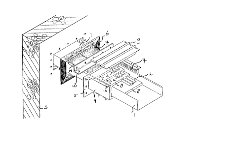
Figure 1 is an exploded view of one embodiment of a system
according to the invention, in which cables 2 inserted
into a lead-through chute 1 are passed through a lead-in
aperture in a wall 3. A safety chute 4 mounted along the
lead-through chute 1 comprises a flange 5 that is
perpendicular to the longitudinal direction of the cables
2, by means of which the safety chute 4 can be attached to
one side of the wall 3 with a gasket 6 interposed. The
safety chute 4, which is substantially rectangular in
section, has all its inner walls provided with sealing
bodies '7 made of a firs-resisting material, of which
there are only two visible in thin figure. The interior of
the safety chute 4 conta~ing a filler 8 applied between,
below and above the cables 2 in the form of spongy bodies
also made of a fire-resisting material. Furthermore the
1o safety chutes 4 comprises a detachable cover plate 9 and a
detachable flanged section 10, both of which can be
attached to a flange 13 of the safety chute 4 running
parallel to the longitudinal direction of the cables 2.
Figure 2 shows the embodiment of the system of Figure 1
fully mounted.
Figure 3 represents an embodiment of a system according to
the invention fully mounted, in which cables 2 inserted
into a lead-through chute 2 are passed through a lead-in
aperture in a floor/ceiling 11. In the assembled state, a
safety chute 4 is sealed off at the top by a closing
device in the form of a separate plate 12 of filler
material, so that for this application it is not necessary
to use the detachable cover plate 9 and the detachable
flanged seot~.on 10 of Figure 1. The component parts of the
system shown in Figure 3 which correspond with those of
Figure 1 have been ind~.cated with the same reference
nuatarala.
Figure 4 is a partly exploded view of an embodiment. of a
system according to the invention in which cables 2 have
been disposed in a lead-through chute 1 as part of a cable
routing plan. A safety chute 4 is attached with its flange
13 to the lead-through chute i by means of a detachable
cover plate 9. This cover plate 9 is here composed of two
cover parts 9' arid two suspension straps 9°°. Tile cover
parts 9' lightly compress the cables 2 and the filler 8.
zf the cables 2 have been laid in a highly irregular
s
pattern w say, cables with large and small diameter side
by side - voids between these cables 2 may, if necessary,
be filled up wittx a fire-resisting cement. Component parts
represented in this figures which correspond with those of
Figure 1 bear the same reference numerals.
Figure 5 shows the system of Figure 4 when fully mounted.
It is worth noting that the sealing bodies 7 represented
in Figures l, 4 and 5 are provided with spacers in the , .
form of ribs 14, so that these sealing bodies 7 Can be
installed along the inner walls of the safety chute 4,
making allowances for an air insulation clearance. As a
result, the filler 2 will be less liable to damage in the
event of a fire by the heat thereby generated. Figure 6 is
a perspective view of such a sealing body 7 containing
several inner cavities 15, here indicated by dashed lines.