Note: Descriptions are shown in the official language in which they were submitted.
CA 02013331 2000-10-18
CONVEYOR BELT CLEANING ARRANGEMENT
THIS INVENTION relates to a conveyor belt cleaning
arrangement and more particularly to a conveyor belt
cleaning arrangement for more effectively removing
residues attached or adhered to the return run of a
conveyor belt.
BACKGROUND ART
Up until this time various arrangements have been known
for removing residues from conveyor belts, including for
example scrapers mounted in such a way as to be held in
contact with the moving surface of a conveyor belt, the
scrapers being used to remove residues from the belt.
While such arrangements have met with some amount of
commercial success, they have not been as successful as
might have been expected, given that there has been a
limitation to the amount of matter that can be removed
from the belt. In particular, the scrapers have not
always been effective since they do not always faithfully
follow the contours of the belt. Furthermore, such
scrapers alone are not always effective for all cleaning
requirement. For example, a sticky substance adhered to
the belt is generally unable to be removed from the belt
by a scraper alone or if it is removed, then it often
adheres to the scraper, thus reducing the efficiency of
the scraper. Further, it has been found that the build-
up of residues and molds on conveyor belts is indicative
of the disadvantages of relying on scraping means alone
to clean conveyor belts.
It has also been found that many particles of substances
adhering to or being built-up on the surface of a
conveyor belt, are of a profile sufficiently flat to pass
under a scraper without being dislodged from the belt.
This problem has been aggravated by the fact that with
flat, compressed
1
201331
particles, there may well be no space for a layer of air
between the belt and particle, as a consequence of which flat
particles are often held tightly on conveyor belts by air
pressure or suction.
DISCLOSURE OF THI~ INVENTION
It is an object of the present invention to overcome or at
least minimize the above and other disadvantages.
It is a further object of this invention to provide a
straight-forward and ea:ficient arrangement for cleaning
conveyor belts.
Other objects of this :invention will become apparent from the
following descr iption.
According to one aspect: of this invention there is provided
an arrangement for cleaning a conveyor belt comprising
scraper means mounted below an underside of a return run of
said belt, such a.s to come into contact with the underside of
said belt; spray means being provided and adapted to apply a
spray of liquid across the underside surface of said belt,
adjacent to and immediately before, or substantially
simultaneous with, contact between said belt and said
scraper.
According to a further aspect of this invention, there is
provided an arrangement for cleaning a conveyor belt,
comprising an elongate beam extending transversely below an
underside of a return run of said belt; scraper means being
attached or mounted to said beam, such as to come into
contact with the underside of said belt; spray means being
provided and adapted to apply a spray of liquid across the
underside surface of said belt adjacent to and immediately
2
2013331
before or substantially simultaneous with, contact between
said belt and said scraper means.
According to a further aspect of this invention there is
provided an arrangement for cleaning a conveyor belt
comprising an elongate beam extending transversely below an
underside of a return run of said belt; scraper means being
so mounted to said beam, such as to come into contact with
the underside of said belt; spray means being provided and
including a plurality of nozzles laterally spaced apart below
the underside of said belt; relative to the longitudinal axis
thereof; means being provided to supply liquid to said
nozzles; said spray means being adapted in use to apply a
spray of liquid across the underside surface of said belt
adjacent to and immediately before or substantially
simultaneous with, contact between said belt and said scraper
means.
According to a farther aspect of this invention there is
provided an arrangement for cleaning a conveyor belt,
comprising an elongate and substantially hollow beam, mounted
so as to extend 'transversely below a return run of a conveyor
belt; said beam extending substantially transverse relative
to the longitudinal axis of said belt; scraper means being
mounted on said beam so as to be in contact with the
underside of saic9 belt; said beam forming a liquid conduit
and reservoir; mE~ans being provided to connect said beam to a
supply of liquid;; spray means being mounted to said beam and
being in communication with liquid within said reservoir;
said spray means being adapted in use to direct a spray of
said liquid at th a underside of said conveyor belt, at or
adjacent, a posii:ion immediately before or substantially
simultaneous with, the underside of said conveyor belt coming
into contact with said scraper means.
3
CA 02013331 2000-10-18
According to a further aspect of this invention there is
provided a method of cleaning a conveyor belt with means
including scraper means mounted below a return run of
said belt, substantially transverse to the longitudinal
axis and direction of travel of said belt, and further
including spray means adapted to apply a spray of liquid
to the underside of said belt, said method including
supplying liquid to said spray means such that a spray of
liquid is applied to the underside of said conveyor belt
at a position adjacent to and immediately before, or
substantially simultaneous with, contact between said
belt and said scraper means.
According to a further aspect of this invention there is
provided a method of cleaning a conveyor belt, with means
including an elongate beam extending transversely below
an underside of said belt and mounting scraper means to
be in contact with the underside of said conveyor belt,
and further including spray means adapted to apply a
spray of liquid to the underside surface of said conveyor
belt, said method including supplying liquid to said
spray means, such that a spray of said liquid is applied
to the underside of said conveyor belt at a position
adjacent to and immediately before or substantially
simultaneously, with contact between said belt and said
scraper means.
In another aspect, the present invention resides in an
arrangement for cleaning a conveyor belt comprising: an
elongated beam mountable transversely below an underside
of a return run of said conveyor belt; a liquid
4
CA 02013331 2000-10-18
reservoir formed in said beam, the liquid reservoir being
connectable to a supply of liquid; a plurality of spray
nozzles laterally spaced apart along the length of the
beam, the spray nozzles being in communication with the
liquid reservoir; scraper means operatively attached to
said beam for contacting the underside of the belt; and
deflector means extending downwardly from said scraper
means, said deflector means being formed so that spray
issuing from the spray nozzles can pass therethrough and
onto the underside of said belt adjacent to and
immediately before, or substantially simultaneously with,
contact between said belt and said scraper means.
BRIEF DESCRIPTION OF THE ACCOMPANYING DRAWINGS
The present invention will now be described by way of
example only and with reference to the accompanying
drawings, wherein:
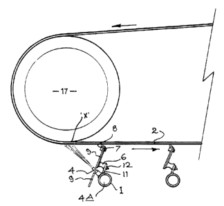
Fig. 1 is a side elevation of a conveyor belt cleaning
arrangement according to the present invention;
Fig. 2 is a corresponding front elevation;
4a
20 1 33M~ 1
Fig. 3 is an isometric view;
Fig. 4 shows a front elevation of an elongate, hollow beam
and asaociat:ed fittings; and
Fig. 5 is a fragmentary side elevation of a conveyor belt;
an end-roller; and an inventive cleaning device.
BEST MODE FOR CARRYING OUT THE INVENTION
The present invention provides an arrangement for the
cleaning of conveyor belts and in particular for applying a
cleaning action to the underside of the return run of a
conveyor belt. As referred to hereinbefore, it has been known
to apply scraper means to the underside of conveyor belts to
attempt to clean same and remove extraneous matter therefrom.
However, this has not always been as successful as might have
been expected.
The present invention provides for a combination of scraper
means and spray ;neaps, the spray means being connected to a
source of liquid, so that a spray of liquid is applied to the
underside of the conveyor belt at a position that is
preferably immediately before or substantially simultaneous
with the contact between the scraper means and the underside
surface of the conveyor belt. It has been found that the
application of a spray of liquid to the underside of the
conveyor belt, ait a position immediately before or
substantially sirnultan~eous with the application of the
scraper means to the belt, greatly assists in removing
extraneous matter from the belt, which matter was not removed
up until this tune by the application of scraper means alone.
In the preferred form o f the invention as shown in the
accompanying drawings, it will be seen with particular
reference to Figs 1 an<9 2 that an elongate hollow beam 1 is
5
20a~331
mounted below the underside of the conveyor belt 2 so as to
extend transversely below the return of the conveyor belt 2,
relative to the longitudinal axis and direction of travel and
direction of travel of the belt 2. The beam 1 is preferably
supported by sups?ort arms or struts 3. Other appropriate
mounting or support means can however be used.
In the preferred form of the invention the beam 1 is provided
with one or more scraper means, generally indicated at 5, the
scraper means 5 being mounted or fixed to the beam 1, for
scraping residues adhered to the underside surface of the
conveyor belt 2. The scraping means 5 include a resilient
member 6 which m<iy be of an elastomeric material, such as for
example natural or synthetic rubber, polyurethane, synthetic
resin or the like; a scraper member 7 formed of an
appropriate material and having for example a tip 8 of hard
material such as tool steel, stainless steel, tungsten
carbide, ceramic polyurethane or the like is provided at the
upper end thereof. In one preferred form of the invention a
deflector plate S1 is mounted to the resilient member 6 and
has at its upper end thereof a scraper member 7 affixed
thereto by appropriate attachment means. The scraping tips
are, in one form of they invention, detachable from
the scraper members 7 so that they may be replaced when worn
or damaged,
In a preferred form of the invention a plurality of scraper
means 5 are mounted in spaced apart relationship along the
length of the beam 1 (and generally transverse to the
longitudinal axis. and direction of travel of the belt 2) by
means of appropriate mounting means, generally indicated at
10, so that the tips 8 are in pressure contact with the
underside surface of the return run 2 of a conveyor belt.
Thus, on movement of the conveyor belt, the tips 8 follow the
undulations and various. contours of the belt and apply a
scraping action thereto, by virtue of the elastic deformation
6
2013331
of the resilient. member 6. As is best seen in Fig. 1 of the
accompanying drawings, mounting means 10 comprises a mounting
plate 11 fastened to i:he resilient member 6 by a plurality of
connection assemblies such as for example nut and bolt
assemblies 12 by way of a cladding plate 12A.
The belt 2 of the conveyor of the present invention is formed
of any appropriate material and for example extends about a
plurality of spaced apart rollers or pulleys 17. Preferably
the rollers or pulleys 17 are spaced apart one from the other
and one or more thereof is or are connected to a source of
power or prime mover, such that on actuation thereof the
belt 2 is caused to move and rotate about the rollers or
pulleys 17; preferably substantially horizontally. In use the
cleaning arrangement of the present invention is provided
below the underside of the return run of such a conveyor, such
that on actuation and movement of the conveyor it will move
over and relative to the cleaning arrangement of the present
invention.
In a preferred farm of the invention as shown in the
accompanying drawings, a plate 9 may extend downwardly past
nozzles 4 (to be described hereinafter) and beam 1; the plate
9 is preferably p~rovide~d with a plurality of apertures such
as 9A positioned and dimensioned so as to receive
therethrough nozzles 4 associated with the spray means, as
will also be described hereinafter. The location of the
nozzles 4 through the apertures 9A will not restrict the
spray of cleaning liquid onto the belt, but the plate 9 will
deflect falling residues and liquid from the belt, thus
preventing or minimizing a build-up of debris and associated
matter on the beam 1. In one form of the present invention,
the portion of the plate 9 below the spray nozzles 4 may be
formed as a separate p late, such as to assist in the
maintenance and c7.eaning of the arrangement.
7
213331
In the preferred form of the invention shown by way of
example only in the accompanying drawings, a plurality of
scraping means T mouni:ed to deflector plates 9 can be mounted
to the beam 1 in a substantially side-by-side; spaced apart
and juxtaposed relationship, extending transversely across
the underside of the c:onveyor belt. If desired however, a
single scraping means 7 can be mounted to the beam 1 and can
extend across th.e underside of the conveyor belt,
substantially transverse to the longitudinal axis or
direction of travel of the conveyor belt.
In the preferred form of the invention, the beam 1 is
substantially hollow and constitutes a reservoir and conduit
for cleaning liquid to~ be applied to the underside of the
conveyor belt 2.
Referring further to the accompanying drawings, the beam
1
preferably
mounts appropriate
spray means,
preferably
in the
form of a plurality of nozzles 4 which are in communication
with the
interior
reservoir
4A of the
beam 1.
In the
preferred form of the present invention a plurality of
laterally spaced apart nozzles 4 are provided along the
length of the be,~m 1. The nozzles 4 (or other spray means)
are prefer ably adjustable, so that the angles) thereof are
adjustable . The nozzles 4 are positioned and attached to
the
beam 1 so as to be in communication with the reservoir 4A
of
the beam and so as to be angled upwardly towards the
1
underside of the belt 2. The nozzles 4 preferably extend
along the length of the beam 1 so as to extend across the
underside of the belt 2 in a direction substantially
transverse to the longitudinal axis of the belt, and the
direction of travel of the belt 2.
In one preferred form of the invention and as shown in the
accompanying drawings, a spray nozzle 4 is provided in
association with each acraper means 7 and deflector plate 9,
8
2013331
holes 9A being provided in the deflector plates 9 so that the
nozzles 4 can pass therethrough.
Referring to Fig. 4 of the accompanying drawings, the beam 1
is shown as being connected to a liquid supply means 13A, by
means of a supply conduit 13. A flow control valve 14 is
provided together with a sieve or strainer 15 and an end cap
16. In the preferred form of the invention the beam 1 is
threaded (or foamed in some other appropriate manner) at
each end so that it is able to receive liquid from either end
according to the layout of a plant. The strainer or sieve 15
is provided to minimize and prevent entry of extraneous
matter into the ;reservoir 4A of the beam 1, from the liquid
supply means. As will be appreciated, the entry of such
extraneous matter would block and interfere with the spray
means and in part:icular the spray nozzles 4.
In use, and on the flow control valve 14 being turned on,
liquid such as for example water or other appropriate
cleaning liquid will pass from the supply conduit 13 through
the sieve or str<~iner 15 and into the reservoir 4A.
Thereafter the pressu re of liquid will cause the liquid to
pass through the nozzles 4 to be directed at the underside of
the conveyor bell: 2.
The cleaning arrangement of the present arrangement is
preferably located below the underside of the return run of a
conveyor belt adjacent to but spaced apart from a position
where the belt 2 leaves an end roller or pulley 17. This is
shown by way of example only in Fig. 5 of the drawings.
In use it has been found that in one form of the invention
the spray means i.n the form of nozzles 4 should be angled
relative to the underside of the conveyor belt 2, such that
the spray of liquid is applied to the underside of the belt 2
at a position adjacent" immediately before or substantially
9
20 1 3331
simultaneous with the application of the cleaning tip 8 to
the underside of the belt 2. It has been found that in this
way, the combination of the cleaning liquid and scraper means
maximises the benefit of the invention.
In one form of th a invention it has been found desirable to
apply the spray of cleaning liquid at a position up to 200 mm
after the belt 2 leaves the roller 17 and before the belt
comes into contact with the scraper means of the present
invention. Referring bay way of example only to Fig. 5 of the
accompanying drawings, it is in one form of the invention
desirable to apply the spray of liquid at a position within
200 mm of the tangential position "X", where the belt 2
leaves the roller 17.
In one form of the invcention it is particularly advantageous
to have the spray mean,, preferably in the form of the
nozzles 4 angled at an angle approximately 45° relative to
the longitudinal axis of the underside of the belt, the spray
from such angled nozzles also being at an angle of
substantially 45°, this resulting in a substantially "chisel"
effect against th a underside surface of the belt 2, which
removes a substantial amount of residue from the underside of
the belt, leaving a relatively small amount of fines in water
suspension to be removed by the scraper means of the present
invention.
In a preferred form of the present invention it is desirable
to have the width of the belt covered by a spray of the
cleaning liquid and to this end where a plurality of spray
nozzles 4 are provided along the length of the beam 1, the
nozzles are so formed and provided, that the spray from each
nozzle overlaps one with the other, such as to provide a
complete coverage across the width of the belt. In one form
of the invention, and by way of example only, there may be a
50 mm overlap of spray from each nozzle 4.
2013331
While the spray means is described by way of example only,
in the form of nozzles, it should be appreciated that other
appropriate forms of spray means can be used.
It should be appreciated that the present invention provides
a substantial advance over the conveyor belt cleaning
arrangements known and used up until this time. The
combination of the spraying of a cleaning liquid and the
scraping of the belt, adjacent one with the other, provides
for substantial advantages as has been described
hereinbefore. There is. a substantial advantage of providing
the spraying means in association with the transverse beam 1
which supports the scraper means so that there is a
substantially unitary arrangement which can be located
below the underside of the conveyor belt and which can be
assembled, disassembled and repaired in a straight-forward
and efficient manner. The provision of the spraying means in
association with the beam 1 supporting the scraper means,
also allows for .accurate angles of spray to be accomplished
relative to the underside of the belt 2 and the scraper
means.
It should be app~_eciated however, that in its broadest
aspect, the invention provides for the utilisation of a
spraying means in association with scraper means. Thus, in
further forms of the invention spray means may be provided
separately from t:he scraper means and may be provided with
their own supply of cleaning liquid which may apply a spray
of cleaning liquid across the underside of a conveyor belt 2
adjacent to and preferably immediately before or
substantially simultaneously with the application of the
scraper means to the underside of a conveyor belt 2, but
independently and separately of, the beam and scraper means.
Such spray means can be mounted in any appropriate manner
below the underside of the conveyor belt, adjacent to
11
201333
appropriate scraping means so as to achieve the objects of
the present invention.
The liquid of the present invention can be any appropriate
cleaning liquid such as for example water, water combined
with one or more additives, a cleaning liquid, detergent or
the like.
INDUSTRIAL APPLICABILITY
The present invention recognises that while scraping means
have been relatively effective in removing matter from the
undersides of conveyor belts, they have not, of themselves,
been appropriate 1_or removing all matters. The present
invention provides a cleaning arrangement which has the
capacity to minimize these problems by substantially
increasing the amount o1. matter that is capable of being
removed from the underside of conveyor belts, essentially by
combining the use of a spray of cleaning liquid with the use
of scraper means.
The spray of cleaning liquid preferably acts as a liquid
chisel to remove bulk residue, and to assist in removing
sticky materials and substances which have previously been
located in grooves and cracks in the belt and over which a
scraper means ear se would pass.
The provision of the liquid spray means substantially
increases the efficiency of the cleaning arrangement of the
present invention. Minute and flat particles which have
previously been left on the conveyor belts, are now able to
be effectively removed by the cleaning arrangement of the
present invention. The use of the liquid spray also acts as a
lubricant, increasing the life of the scraper tips of the
present invention and reducing the wear on the conveyor belt.
The lubricating action of the liquid spray also reduces
12
2013331
friction and minimize: heat build-up. Further, the cleaning
liquid is continuously washing away residues collected by the
scraper so as to ensure that the cleaning arrangement does
not become clogged. The deflector plates of the present
invention assist in that regard.
In the preferred form of the invention, the beam 1 which acts
as a mounting beam for the scraper means also forms a
reservoir for the cleaning liquid, cleaning nozzles
preferably being mounted to the beam so that the spraying
means and scraper means are formed in a substantially unitary
construction which allows for effective mounting,
utilisation, replacement and repair.
It should be appreciated that the present invention provides
substantial advantages over arrangements used up until this
time. Further, modifications and improvements may be made to
this invention without departing from the scope thereof as
defined by the appended claims.
13