Note: Descriptions are shown in the official language in which they were submitted.
20133~7
TITLE OF INVENTION
Superconductor Jointed Structure
BACKGROUND OF T~E INVENTION AND RELATED ART STATEMENT
The present invention relates to a jointed structure
comprising at least two kinds of oxide superconductor having
different melting points.
In recent years, oxide superconducting materials have
drawn attention for their high critical temperatures, and
their applications in such fields as electric power, NMR
apparatus, magnetic shielding and the like are expected.
Measurement of very weak biomagnetism has become
possible by using an oxide superconducting material and a
simple cooling apparatus utilizing liquid nitrogen.
Accordingly, further application of oxide superconducting
material is expected in medical science and medical care, in
particular.
In measurement of biomagnetism, the apparatus used
therefor must be able to not only contain a living body but
also form a space of very low magnetic field. As the
container for living body, cylindrical structures have been
proposed generally. In order for a cylindrical structure to
form a space of very low magnetic field, it is necessary
that a supercurrent strong enough to shield geomagnetism
flow uniformly throughout the all parts of the cylinder.
20133~7
Accordingly, it has hitherto been thought that the cylinder
for containing a living body must be produced in one piece.
In production of oxide superconductor structures of large to
small sizes, however, it is difficult to effect molding and
firing always in one piece.
A cylinder used as a container for measurement of
biomagnetism must have a minimum diameter of about 1 m and a
length of about 3 m when the cylinder is used for, for
example, a living body.
In producing such a large cylinder in one piece, a
large electric furnace is required (this is not practical)
and moreover it is thought to be extremely difficult with
the present technique to obtain an oxide superconductor
cylinder having uniform properties throughout the cylinder.
Hence, it becomes necessary in production of various
oxide superconductor structures to prepare divided parts and
then joint these parts.
Currently, in jointing oxide superconductor parts, it
is known to use, as a jointing layer, an oxide
superconducting material having the same composition as the
oxide superconductor parts to be jointed. It is also known
to add a small amount of a non-superconducting material to
said superconducting material in order to improve the
adhesion between the jointing layer and the oxide
~ 0 1 '~ 7
superconductor parts to be jointed.
SUMMARY OF TIIE INVENTION
The above conventional jointing method of using, as a
jointing layer, an oxide superconducting material having the
same composition as the oxide superconductor parts to be
jointed includes jointing by melting and jointing by
sintering. In the jointing by melting, the oxide
superconductor parts to be jointed cause deformation,
thereby reducing their superconducting properties. In the
jointing by sintering, the joint strength is weak and
insufficient in practical application. Meanwhile in the
jointing method wherein a non-superconducting material is
added, the resulting joint layer has significantly reduced
superconducting properties and is not practical.
The present invention is intended to provide, in
jointing oxide superconductor parts to obtain an oxide
superconductor jointed structure, a joint layer which gives
a strong joint strength and which causes no reduction in
superconducting properties.
The present invention is also intended to provide a
container for biomagnetism measurement which is applicable
in industry. It has conventionally been thought that only
containers of uniform oxide superconductor produced by one-
2~133~
., .
piece molding, etc. can shie]d geomagnetism to form a spaceof very low magnetic field; however the present invention is
intended to prepare divided oxide superconductor cylinder
parts and then joint these parts to produce a long oxide
superconductor cylinder jointed.
The present invention is further intended to specify,
in obtaining a jointed cylinder of high magnetic
shieldability, the site(s) for division and the condition of
jointing.
According to the present invention there is provided a
jointed structure made of at least two oxide superconducting
materials of different melting points, which consists of two
or more high meltIng oxide superconducting material parts
and at least one low melting oxide superconducting material
part and which is constituted in such a way that each one
such low melting oxide superconducting material part is
interposed between each two such high melting oxide
superconducting material parts.
In the present invention, at least two kinds of oxide
superconducting materials of di~ferent melting points are
used in combination; that is, higher melting point oxide
superconducting materials are jointed by a joint layer which
is a lower melting point oxide superconducting material; the
resulting oxide superconductor jointed structure has a large
2~33~7
adhesion strength and maintains the superconducting
properties of the higher melting point oxide superconducting
material parts.
The jointed structure comprising at least two kinds
oxide superconducting materials of different melting points
according to the present invention is suitably used in
production of various oxide superconductor structures.
The present invention provides, in particular, a large
oxide superconductor cylinder obtained by firstly preparing
divided parts of the cylinder and then making these parts
into one piece using the above-mentioned joint layer. This
oxide superconductor cylinder having a jointed layer,
although not produced by one-piece molding, can shield
geomagnetism.
It has hitherto bee;n thought that only the cylinder
produced by one-piece molding can shield geomagnetism, but
industrial production of such a large cylinder used for
biomagnetism measurement has been difficult. Therefore, the
large oxide superconductor cylinder according to the present
invention is very useful.
BRIEF DESCRIPTION OF TIIE DRAWINGS
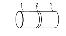
Fig. 1 is a schematic illustration of one embodiment of
the jointed structure of the present invention.
2~3'~5:7
Fig. 2 (A) is a schematic illustration of a jointed
cylinder which is other embodiment of the present invention,
and Fig. 2 (B) is a sectional view taken at a A-A line, of
the joint area of the jointed cylinder of Fig. 2 (A).
Fig. 3 is a schematic illustration of a cylindrical
apparatus for measurement of magnetic field shieldability.
Fig. 4 (A) is a schematic illustration of a jointed
panel which is other embodiment of the present invention,
and Fig. 4 (B) is a sectional view taken at a line B-B, of
the joint area of the jointed panel.
Fig. 5 is a schematic illustraion of a panel-shaped
apparatus for measurement of magnetic field shieldability.
DETAILED DESCRIPTION OF THE INVENTION
As the oxide superconducting materials of the present
invention, there are used, for example, M-Ba-Cu-O type
compounds [M is at least one element selected from Sc, Tl, Y
and lanthanide elements (e.g. La, Eu, Gd, Er, Yb, Lu)] and
Bi-Sr-Ca-Cu-O type compounds, all having a multilayered
perovskite structure.
In the present invention, oxide superconducting
materials of different melting points are used in
combination. A difference of melting point temperature
between the higher melting point oxide superconductor and the
2~33~7
lower melting point oxide superconductor is from 5O C to
200OC, preferably from 10 C to 100C. When the temperature
difference is less than 5OC, the higher melting point
superconductor remelts when fired, resulting in
deterioration of superconducting properties. When the
temperature difference is more than 200OC, it is not
possible to obtain the sufficient superconducting properties
in the form of the usual superconducting material powder
because the firing needs to be done at 800O C or less. In
that case, the oxide superconducting material of lower
melting point preferably has, even after melting, a high
critical current density owing to crystallization.
Preferably, an M-Ba-Cu-O type compound and a Bi-Sr-Ca-Cu-O
type compound are used in combination. M-Ba-Cu-O type
compounds wherein M is a lanthanide metal, such as
YBa2 Cu3 0~, LaBa2 Cu3 07 and the like have a melting point of
960OC or more in the atmosphere and a sintering temperature
of 920-9600C. Meanwhile, Bi-Sr-Ca-Cu-O type compounds such
as Bi2 Sr2CaCu2Ox, Bi2 Sr2Ca2 CU3 X and the like, as well as
compounds obtained by incorporating Pb and/or Sb into a Bi-
Sr-Ca-Cu-O type compound, begins partial melting at 860-
9200 C in the atmosphere although the temperature differs
slightly depending upon their compositions. It is well known
that Bi-Sr-Ca-Cu-O type compounds show superconducting
2Q~ ~3~7
properties owing to the crystallization after melting.
Accordingly, when a Bi-Sr-Ca-Cu-O type compound is used as a
joint layer for parts of M-Ba-Cu-type compound (e.g.
YBa2Cu3O~), the molten jointing by the Bi-Sr-Ca-Cu-O type
compound can be conducted at temperatures of 920OC or less,
and the parts can be jointed with no creep to obtain a
jointed structure comprising parts of M-Ba-Cu-O type oxide
superconducting material and a joint layer of Bi-Sr-Ca-Cu-O
type oxide superconducting material interposed between the
parts.
Bi-Sr-Ca-Cu-O type compounds can give various
superconducting phases by taking different compositions or
containing various additives, and have different melting
points in the range of 860-920OC. Accordingly, by using at
least two different superconducting phases each of Bi-Sr-Ca-
Cu-O type compound, there can be obtained another jointed
structure comprising parts of higher melting point Bi-Sr-Ca-
Cu-O type superconductor and a joint layer of lower melting
point Bi-Sr-Ca-Cu-O type oxide superconductor interposed
between the parts.
In one example of using two Bi-Sr-Ca-Cu-O type
compounds of different compositions to obtain a jointed
structure, when the Bi content in the composition of a Bi-
Sr-Ca-Cu-O type oxide superconducting material to be used as
2~133~
a high melting superconducting material is increased, the
resulting oxide superconducting material has a lower melting
point and can be used as a low melting oxide superconducting
material. For example, when Bi2 Sr2 Ca2 Cu3 x of
stoichiometric composition is used as a high melting oxide
superconducting material, there can be used, as a low
melting oxide superconducting material, Bi2Sr2CalCu2Ox of
stoichiometric composition, Bi2 5 Sr2 Ca2 Cu3 0~ of
nonstoichiometric composition, or the like.
Also when a noble metal (e.g. Au, Ag) or Pb is added to
a Bi-Sr-Ca-Cu-O type compound of stoichiometric
composition,the resulting composition has a lower melting
point without reducing the superconducting properties of the
former compound. Thus, a Bi-Sr-Ca-Cu-O type compound of
stoichiometric composition can be used as a high melting
oxide superconducting material, and a composition obtained
by adding a noble metal~or Pb to the above compound can be
used as a low melting oxide superconducting material. The
addition amount of noble metal or Pb is 0.1% by weight or
more, preferably 1-20% by weight. When the amount is less
than 0.1% by weight, no effect of melting point reduction is
observed. When the amount is more than 20% by weight, there
occurs deterioration of superconducting properties.
The jointed structure of the present invention can
~O~l33~7
consist of two or more higher melting point oxide
superconductors and at least one lower melting point oxide
superconductor, each made of one of the above mentioned
oxide compounds, or can take such a form that both the
higher melting point oxide superconductor and the lower
melting point oxide superconductor are formed on a substrate
made of a metal, a ceramic or the like. When a metal
substrate is used, it is preferable that the metal substrate
surface be subjected to a pretreatment as necessary,
depending upon the type of metal, the type of superconduct-
ing material, etc. For example, when Bi-Sr-Ca-Cu-O type
compounds are used as oxide superconducting materials, it is
preferable that a nonreactive intermediate layer of ceramic,
noble metal or the like be formed on the substrate in
advance because said compounds have high reactivity with the
substrate metal.
In the present invention, the jointing of higher
melting point oxide superconductors and a lower melting
point oxide superconductor can be effected, for example, by
making a lower melting oxide superconducting material powder
into a slurry using an appropriate solvent, coating the
slurry on the joint area of each higher melting point oxide
superconductor to be jointed, jointing each two of these
joint areas, and heating each new joint area to the melting
20~3~
point of the low melting oxide superconducting material or
more to melt the low melting oxide superconducting material.
The jointing may also be effected by preparing a molded
article of a low melting oxide superconducting material to
later become a ~oint layer, jointing one end of this molded
article with one high melting superconducting material part
at the melting point of the molded article, and jointing the
other end of the molded article with another high melting
oxide supereonducting material part at the same melting
point. The jointing may also be effeeted by placing a
molded article of low melting oxide superconducting material
between two high melting oxide superconducting material
parts to be jointed and heating the molded article to its
melting point to joint the two parts. The heating for
effecting jointing is not restricted particularly and can be
achieved by various methods any as long as it can allow the
joint area to reach the melting point of the low melting
oxide superconducting material. For example, the heating
can be effected by placing the structure consisting of the
higher melting point oxide superconductors to be jointed and
the lower melting point oxide superconductor in an electric
furnace, or by applying a laser beam local to the joint
area.
In jointing higher melting point oxide superconductors
2~ 3~7
each formed on a substrate of metal or the like, using a low
melting oxide superconducting material, it is preferable
that, prior to the jointing, each two adjacent substrates be
connected by fastening the flanges of the substrates with
bolts and nuts, or by welding.
In the present invention, the thickness of the joint
layer can be determined appropriately depending upon the
application purpose of the jointed structure. When the
jointed structure is used for the purpose of, for example,
magnetic shielding, the thickness of the joint layer is
preferably 2 mm or less usually.
The jointed structure of the present invention has a
high strength. The reason is presumed to be that the low
melting oxide superconducting material causes partial
melting and enters into the surface pores or cracks of the
higher melting point oxide superconductors to be jointed and
as a result high adhesion is obtained. Another reason for
high strength is that the jointed structure of the present
invention comprises oxide superconductors having a
multilayered perovskite structure and their thermal
expansion coefficient is in a range of about 10x10- 6 / C to
about 15x10- 6 / C.
When the jointed structure of the present invention is
used as a structure for magnetic shielding having a hollow
2 ~ .~ 1C~ ~t~
portion so as to give rise to magnetic shielding therein, it
is preferable that the structure be constructed so as to
include joint layer(s) in a direction crossing the axis of
the structure because the magnetic flux of external magnetic
field comes into the hollow portion from the both ends of
the structure. For example, in producing a jointed
cylindrical structure, at least two cylindrical parts of
shorter than 1 m obtained by dividing the structure in a
direction crossing the axis of the structure are prepared,
each one joint layer is placed between each two of the
divided parts, and jointing of the parts is effected by
melting the joint layer. The length of the jointed
cylindrical structure is not restricted particularly but is
generally 1 m or more.
The division of the cylindrical structure in a
direction crossing the axis can be made preferably at an
approximately right angle (90C) to the axis, but can be
made at 90+10 to the axis. When the division is made at
an angle more than 90+10, no sufficient magnetic shielding
is obtained and, when the resulting cylindrical structure is
used as a container for biomagnetism measurement, it is
impossible to obtain a space of very low magnetic field.
It is preferable that each of the joint layers be
provided between each two divided cylindrical parts at
13
2~33~7
intervals of 1/10 or more of the diameter of the cylinder.
Accordingly, the divided cylindrical parts used in the
present invention each have the same diameter (usually about
1 m) as the jointed cylinder and a length of 0.1-1.0 m.
When the length of each divided part is less than 0.1 m, the
joint layers having a lower critical current density exist
at intervals of less than 0.1 m, and the resulting jointed
cylinder has a low shielding effect for magnetic field and
is not suitable for use as a container for biomagnetism
measurement. When the length of each divided part is more
than 1.0 m, such a part is not practical. Divided parts of,
for example, 1 m in diameter and 1 m or less in length can
be fired in an conventional electric furnace, and divided
parts of 0.5 m or less in length can be fired in a
conventional electric furnace of smaller size, whereby an
oxide superconductor jointed cylinder which is uniform
throughout the entire portion can be produced easily.
In the above cylindrical structure wherein magnetic
shielding takes place in the hollow portion, the effect of
magnetic shielding is not impaired even if the joint layers
have lower superconducting properties than the divided
cylindrical parts. Therefore, the critical current density
(Jc) in the joint layers may ~e lower than the Jc of the
divided cylindrical parts. In general, the Jc in the joint
14
2~ 3~7
layers differs by the thickness of the oxide superconductor
constituting the cylinder, or by the thickness of the oxide
superconductor layer having superconducting properties when
the cylinder takes a form of an oxide superconducting layer
formed on a substrate of metal or the like. It has been
made clear in the present invention that when the thickness
of oxide superconducting material of cylinder is, for
example, 1 mm, the jointed cylinder can exhibit magnetic
shielding sufficiently if the joint layers are made of an
oxide superconducting material having a Jc of 4 A/cm2 or
more and have a width of 0.5 mm or less.
In order to shield geomagnetism completely, it is
generally necessary to reduce an external magnetic field by
at about 5 G in view of the fluctuation of geomagnetism and
the safety factor of shielding. Therefore, in the case of,
for example, a cylindrical structure of 1 m in diameter and
3 m in length, it is necessary that the cylindrical
structure have a diamagnetic current of about 4 A per 1 cm
of the cylinder in the axial direction, i.e. a supercurrent
at the outer surface of the cylinder. To satisfy this
requirement, it has been tjhought that when the oxide
superconductor constituting the cylinder has a thickness of,
for example, 1 mm, the oxide superconducting material must
have a Jc of 40 A/cm2 and, when the oxide superconducting
~3~7
_
material has a thickness of 100 ~m, the material must have a
Je of 400 A/cm2. It has also been thought that when a
cylindrical structure is produced by jointing divided parts
from technical reasons, an external magnetic field possibly
comes into the strueture through the joint areas, making it
impossible to reduce the external magnetic field.
Meanwhile, the present inventors studied on the amount
of the external magnetic field (geomagnetism) coming into a
jointed eylindrieal structure having joint layer(s) in the
direction crossing the cylindrical axis. According to the
study, when the jointed cylindrical structure was, for
example, an oxidè superconductor cylinder of 1 m in
diameter, 3 m in length and 1 mm in thickness, which
consisted of two divided parts of equal size and one joint
layer of 0.5 mm in width placed between the two divided
parts substantially perpèndicularly to the cylindrical axis,
the amount of the geomagnetism which came into the jointed
cylinder was about 10%. Therefore, as mentioned above, when
the oxide superconductor constituting a jointed cylinder has
a thickness of 1 mm, it is sufficient if the joint layer
having a width of 0.5 mm has a Jc of 4 A/cm2 or more.
In the present invention, the jointing of divided
cylindrical parts can be effected by various methods such as
(1) a method wherein a thin cylindrical oxide superconductor
16
2~133~7
of lower melting point to later become a joint layer is
placed between divided superconductor cylindrical parts of
higher melting point and subjected to local melting to
effect jointing, or a slurry of a lower melting oxide
superconducting material is coated on the end surfaces of
divided superconductor cylindrical parts of higher melting
point and each two of these coated end surfaces are
contacted with each other and subJected to partial firing to
effect jointing, (2) a method wherein each two divided
superconductor cylindrical parts are contacted with each
other and subjected to local melting to effect jointing, and
(3) a method wherein each two divided superconductor
cylindrical parts are coated at the end surfaces with a
slurry of the same oxide superconducting material as that
constituting the divided cylindrical parts and each two of
these coated end surfaces are contacted with each other and
subjected to partial firing to effect jointing.
The partial melting or firing in the above jointing
methods can be effected by, for example, the application of
a laser beam or the use of a furnace for local firing.
EXAMPLES
The present invention is described in more detail by
way of Examples. However, the present invention is in no
2~ 33~7
way restricted to the Examples.
Example 1
A YBa2 Cu3 07 powder was subjected to in-mold pressing to
obtain pellets. The pellets were fired at 950OC for 3 hours
in oxygen to obtain Y-based columnar sintered articles
having a diameter of 20 mm and a height of 10 mm.
A Bi2Sr2CaCu2 08 powder was subjected to in-mold
pressing to obtain a Bi-based columnar molded article having
a diameter of 20 mm and a height of 1.5 mm. This molded
article was interposed between the Y-based sintered
articles, as shown in Fig. 1, and they were subjected to
press bonding. In Fig. 1, the numeral 1 refers to Y-based
sintered articles and the numeral 2 refers to a Bi-based
molded article.
The press-bonded article was heated at 900OC for 30
minutes in oxygen to partially melt the joint layer, and the
partially melted area was crystallized at 8600C in oxygen to
allow the area to have superconducting properties.
Thereafter, a metal jig was fixed to each one end of
the press-bonded article with an adhesive, and the article
was measured for adhesion strength by a tensile strength
tester. The tensile strength was 60-80 MPa which was about
80% of the tensile strength (70-100 MPa) of the Y-based
18
~0:~33~7
_
sintered articles When there was repeated the same
procedure as above except that there was used, as the joint
layer, the above Y-based molded article, the adhesion
strength was 20-30 MPa.
A rod-shaped sample of 2 mm x 2 mm x 20 mm was cut out
from the above press-bonded article whose joint layer had
been subjected to partial melting and subsequent
crystallization, so that the joint layer was at the center
of the rod-shaped sample. The rod-shaped sample was
measured for critical current density (Jc) at the boiling
point (77 K) of liquid nitrogen, by a four-probe method.
The sample had a Jc of 100-200 A/cm2 which was about the
same as the Jc of the Y-based sintered articles.
Example 2
The outer surface of an Inconel 625-made cylinder
having a diameter of 100 mm, a length of 120 mm and a
thickness of 2 mm was subjected to Ag plating at a thickness
of 100 ~m. On the resulting Ag layer a slurry obtained by
dissolving a Bi2Sr2CaCu2Ox powder (average diameter = 2 ~m)
in a solvent (isopropyl alcohol) was spray-coated, at a
thickness of 500 ~m. The resulting cylindrical article was
subjected to partial melting at 890C for 15 minutes then
cooled at a rate of 1 C/min, and crystallized at 850OC for
19
2~ 33~7
15 hours in an oxygen atmosphere in an electric furnace.
The resulting cylindrical sintered article was annealed in
the electric furnace; then, the furnace inside was purged
with nitrogen; the article was heat-treated at 400OC for 10
hours. As a result, the Bi-based superconducting layer
formed on the cylindrical substrate had a thickness of 300
~m. According to the above process, there were prepared
four cylindrical sintered articles each having a Bi-based
superconducting layer.
Next, as shown in Fig. 2 (A), the four cyIindrical
sintered articles 11 were jointed at the end surfaces to
prepare a jointed cylinder 9.
Fig. 2 (B) shows a sectional view taken at an A-A line,
of the portion a of the joint area 12 of the jointed
cylinder 9 of Fig. 2 (A). The Inconel-made cylindrical
substrates 10 had flanges 3 at the ends inside the cylinder
and each two these flanges were fixed to each other at the
four points with bolts 4 and nuts 5. The joint areas of the
plated Ag layers 6 were coated with an Ag paste 7. The
joint areas of the Bi-based superconducting layers 8 were
coated with a slurry obtained by dissolving a mixture of (a)
the same Bi2Sr2CaCu2Ox powder as used in the formation of
the Bi-based superconducting layers 8 and (b) 3% by weight
of PbO, in isopropyl alcohol. The resulting jointed
20133!~7
._
cylinder having a length of 480 mm was subjected to firing
at 870O C for 30 minutes, then the furnace temperature was
lowered and crystallization was effected at 850OC for 15
hours in an oxygen atmosphere in an electric furnace. The
cylinder was then annealed and heat-treated at 400OC for 10
hours in a nitrogen atmosphere. The superconductor joint
layer had a thickness of 600 ,um.
In the above firing at 870OC for 30 minutes in an
oxygen atmosphere, the Bi-based superconducting layers 8
were not melted and only the portions coated with the PbO-
containing Bi2Sr2CaCu2Ox slurry were partially melted toform joint areas 12. Simultaneously, the Ag paste 7 was
solidified by the firing to bond the Ag layers 6.
As a result, there was obtained a jointed cylinder 9.
This jointed cylinder 9 having a diameter of 100 mm and
a length of 480 mm was measured for magnetic shieldability
using a cylindrical apparatus for measurement of magnetic
shieldability, schematically illustrated in Fig. 3. In Fig.
3, the jointed cylinder 9 was placed inside a container 14
for liquid nitrogen; the container 14 was filled with liquid
nitrogen; and an external magnetic field was applied to the
jointed cylinder 9 by an electromagnet 15; using a Gauss
meter 13 placed inside the jointed cylinder 9, there was
measured a maximum external magnetic field (this is the
2~33~7
magnetic shieldability of the jointed cylinder 9) at which
the magnetic field inside the jointed cylinder 9 began to
exceed the background. As a result, the magnetic
shieldability was 12 G.
After this measurement, the joint areas of the jointed
cylinder 9 caused neither peeling nor cracking.
Example 3
A SUS 310 stainless steel-made cylinder having a
diameter of 100 mm, a length of 120 mm and a thickness of 2
mm was coated, at the outer surface, with a slurry
containing a glass frit for porcelain enamel, at a thickness
of 100 ~m. Thereonto was press-bonded an Ag foil having a
thickness of 100 ~m. The resulting cylinder was fired at
900OC for 1 hour in the atmosphere. Using the fired
cylinder as a substrate, there was repeated the same
procedure (molding and firing) as in Example 2, to prepare
four cylindrical sintered articles each having a Bi-based
superconducting layer.
The four cylindrical sintered articles were jointed in
the same procedure as in Example 2. In jointing, the Ag
foil layers were jointed by coating an Ag paste at the joint
areas; the Bi-based superconducting layers were jointed by
coating, at the joint areas, a slurry obtained by dissolving
20~ 33~7
a Bi2Sr2CaCu2Ox powder and 5% by weight of Ag2O in
isopropylalcohol; then, the same procedure as in Example 2
was applied to obtain a jointed cylinder.
The jointed cylinder was measured for magnetic
shieldability in the same manner as in Example 2. The
magnetic shieldability was 10 G. After the measurement, the
joint areas of the cylinder caused neither peeling nor
cracking.
Example 4
An inconel 825-made flat substrate of 333 mm x 333 mm x
1 mm was subjected at one side to Ag plating at a thickness
of 100 ~m. On the Ag layer was formed a Bi-based
superconducting layer by the same coating and firing
procedure as in Example 2, to prepare nine flat sintered
articles having a Bi-based superconducting layer at a
thickness of 300 ~m.
Then, as shown in Fig. 4 (A), the nine flat sintered
articles 21 were jointed at the edges to prepare a jointed
panel 29.
Fig. 4 (B) shows a sectional view taken at a B-B line,
of the portion b of the joint areas 22 of the jointed panel
29. As shown in Fig. 4 (B), each flat substrate 20 had
projections 23 at the edges at the side opposite to the Ag-
2 ~ 7
plated side; each two adjacent flat substrates 20 werejointed by fixing their projections 23 to each other at two
points with bolts 24 and nuts 25. The plated Ag layers 26
were jointed at the joint areas 27 by TIG welding. The Bi-
based superconducting layers 28 were jointed at the joint
areas 22 by coating a slurry obtained by dissolving (a) the
same Bi2Sr2CaCu2Ox powder as used for formation of the Bi-
based superconducting layers 28 and (b) 1% by weight of PbO
in isopropyl alcohol and then scanning a laser beam along
each joint area to apply the beam only to each coated
portion.
In this case, the laser beam energy and the scanning
speed were controlled so that each joint area was melted
partially. After the jointing, the laser energy was reduced
to such a level that each joint area was not molten, and the
scanning was continued in the same manner to effect a heat
treatment to obtain a jointed panel 29 of about 1 m2. The
superconductor joint layer had a thickness of 500 ~m.
The jointed panel 29 was evaluated for magnetic
shieldability using a panel apparatus for measurement of
magnetic shieldability, schematically illustrated in Fig. 5.
In Fig 5, the jointed panel 29 was placed in a container 34
for liquid nitrogen; the container 34 was filled with liquid
nitrogen; an external magnetic field was applied to the
24
2~133~7
jointed panel 29 by an electromagnet 35; using a Gauss meter
33 placed so that the container 34 was between the
electromagnet 35 and the Gauss meter 33 and the Gauss meter
was at the back of the jointed portion 36 which was the
intersection of the joint areas 22 of the jointed panel 29,
there was measured a maximum external magnetic field (this
is the magnetic shieldability of the jointed panel 29) at
which the magnetic field behind the jointed panel 29 began
to exceed the background. As a result, the magnetic
shieldability was 30 G. After this measurement, the joint
areas of the joint panel 29 caused neither peeling nor
cracking.
For comparison, the same flat sintered articles 21
having a Bi-based superconducting layer, as used above were
jointed in the same manner as above except that the jointing
of the Bi-based superconducting layers 28 were not effected.
The jointed panel was measured for magnetic shieldability in
the same manner. The magnetic shieldability was
substantially zero.
As is clear from the above results, a Bi-based
superconducting composition containing Pb and thereby having
a reduced melting point has substantially the same
superconducting properties as the Bi-based superconducting
composition before Pb addition and posseses sufficient
20~33~7
magnetic shieldability. It was also confirmed that, in
partial melting of joint areas by electric furnace or laser
beam, the Bi-based superconducting layers adjacent to the
joint areas are not affected by the melting and accordingly
not deteriorated.
Example 5
There were mixed a Y2O2 powder (purity = 99.9%, average
particle diameter = 0.4 ~m), a BaCO3 powder ~average
particle diameter = 0.8 ~m) and a CuO powder (average
particle diameter = 2.5 ~m) at a molar ratio of 1 : 4 : 6.
The mixture was calcinated at 940C for 10 hours in the
atmosphere to synthesize a YBaCu3 07 powder.
2 kg of the YBaCu3 07 powder was mixed with 50 g of
polyvinyl butyral (PVB) as a sintering agent and 5 g of a
nonionic dispersant. The resulting mixture and 1 kg of
zirconia grinding media were placed in nylon-made container
containing 2 liters of toluene. The container was placed in
a rotary mill to effect grinding and mixing for 16 hours to
obtain a slurry. The slurry was subjected to spray drying
to obtain a powder having an average particle diameter of 50
~m.
The powder was subjected to in-mold pressing by a
hydrostatic pressure of 2.5 ton/cm2 to prepare one
26
cylindrical molded article (A) of 110 mm (outside diameter),
350 mm (height) and 8 mm (thickness) and three cylindrical
molded articles (B) of 110 mm (outside diameter), 120 mm
(height) and 8 mm (thickness).
All of these molded articles (A) and (B) were fired at
250OC for 6 hours, 880C for 10 hours and 960OC for 6 hours,
and annealed at a rate of 1C/min in an oxygen atmosphere
obtain respective cylindrical sintered articles.
The Y-based superconductor cylindrical sintered article
(A) had an outside diameter of 100 mm, a height of 300 mm
and a thickness of 6 mm, and the Y-based superconductor
cylindrical sintered articles (B) had an outside diameter of
100 mm, a height of 100 mm and a thickness of 6 mm.
Then, the end surfaces of the three Y-based
superconductor cylindrical sintered articles (B) were
smoothened by a SiC paper; the end surfaces to which are
become a joint surface were coated with the same YBaCu3 07
slurry as above; the three articles were jointed, and
subjected to firing and annealing in an oxygen atmosphere in
the same manner as above to obtain a Y-based superconductor
cylindrical sintered article (B') of 300 mm in height having
joint areas. The Jc of the joint areas was 20 A/cm2 and was
lower than the Jc (100 A/cm2) of the main part of the Y-
based superconductor cylindrical sintered article (B').
_~ 2~33~7
Each of the superconductor sintered articles (A) and
(B') was immersed in liquid nitrogen in a space of very low
magnetic field (10-4 G) magnetically shielded by permalloy,
and placed in a superconducting state. Each superconductor
sintered article was taken out into geomagnetism while being
immersed in liquid nitrogen, and measured for magnetic
intensity at the center of the cylindrical sintered article
by a flux-gate type magnetic meter.
As a result, in both of the superconductor cylindrical
sintered articles (A) and (B'), the magnetic intensity in
the direction parallel to the cylindrical axis was 10- 3 G or
less, and geomagnetism was shielded completely.
Comparative Example 1
In the same procedure as in Example 5 were prepared six
semicylindrical molded articles (C) each having a shape
obtained by dividing ~a cylinder of 110 mm (outside
diameter), 120 mm (height) and 8 mm (thickness) into two
equal parts in the axial direction, and the molded articles
were fired to obtain six Y-based superconductor
semicylindrical sintered articles (C). The superconductor
sintered articles (C) were jointed in the same procedure as
in Example 5 to obtain a Y-based superconductor cylindrical
sintered article (C') of 300 mm in height having joint
areas.
28
20~33~7
The superconductor cylindrical sintered article (C')
was measured for magnetic shieldability in the same manner
as in Example 5. As a result, the magnetic intensity in the
direction parallel to the cylindrical axis of the
superconductor sintered article (C') was 10-2 G, and it was
confirmed that the part of geomagnetism came into the
sintered article (C').
It was confirmed from Example 5 and Comparative Example
1 that in the oxide superconductor cylinder having joint
areas in the axial direction, there is leakage of part of
geomagnetism, while in the oxide superconductor cylinder of
the present invention obtained by jointing divided
cylindrical parts so that the joint areas exist in the
direction crossing the cylindrical axis, there can be
obtained about the same very low magnetic field as in a one-
piece-molded cylinder made of the same oxide superconducting
material and there is no leakage of magnetic flux from the
joint areas.
29