Note: Descriptions are shown in the official language in which they were submitted.
3 7 2
~.,
Condensate T~ or Systems under Pressure
This invention relates to a so-called condensate
trap, that is to say, means for discharging condensate
from fluid systems under pressure.
In pressurised gas, vapour or air systems there is
a tendency for water or oil condensate to separate out,
for example vapour from atmospheric air or oil from
compressors in the system. As a rule this condensate
is very aggressive and accordingly it has to be
collected within the closed system and discharged from
time to time, but without losing any significant
quantity of the gas or air in the system and without
any significant drop in pressure.
For this purpose it is known to use
float-controlled condensate traps but in these there is
the danger of sticking, which can lead to the
condensate not being discharged or alternatively to the
escape of the compressed air or gas and complete loss
of pressure.
In one known form of trap (DE-P 31 49 830), these
drawbacks have been overcome and this device has
generally speaking proved satisfactory. However, where
this device is used with only one sensor it is
necessary for the solenoid-operated valve, trigyered
by a siynal from this sensor, to be time-controlled and
here again there is the danger of possible loss of
pressure and high energy costs. On the other hand,
when i~t is used with at least two separate sensors
there is the problem that they take up a significant
amount of space and so the equipment is bulky and
difficulties arise in installation and in layout.
-` 2~3372
To this must be added that the stress on the.
outlet valve is relatively severe duriny operation, and
the construction is, as a whole, expensive.
The principal object of the present invention is
to provide an improved form of condensate trap in which
the loading or stress on the discharge valve is less
severe in use and of which furthermore the overall
construction is simpler and more compact and
consequently more economical.
This object is achieved according to the invention
by a condensate trap for a system under pressure
comprising a condensate collecting chamber, said
chamber having means for permanently connecting it into
said system and having an outlet, a diaphragm valve
normally closing said outlet, sensing means within said
chamber, said sensing means comprising a tube
projecting into said chamber and at least two separate
sensors within said tube, said sensors being of an
electric capacitive type and being responsive to
different levels of liquid condensate within said
chamber, a pilot valve in a chamber, a connection
between said sensors and said pilot valve whereby to
open and close said pilot valve in response to said
di~ferent levels o~ condensate, said pilot valve
controlling operation of said diaphragm valve.
Thus although there are at least two sensors
sensing different condensate levels there is only a
single body, the tube, projecting into the collecting
chamber. The tube is pre~erably made of electrically
non-conducting material, e.g. ceramic or plastics.
There are preferably just two sensors.
.
~33~
When the condensate reaches a predetermined higher
level the pilot valve is actuated and this in turn
opens the diaphragm valve, allowing the condensate to
be discharged. When the level falls to a predetermined
lower value, closing of the diaphragm valve is
initiated.
Preferably the signal for closing the diaphragm
valve is only produced after a predetermined time delay
following sensing of the condensate level having
reached the said predetermined lower value. This
means that the actual minimum level reached before the
valve is closed can be lower than the position of the
lower sensor, and so the tube containing the sensor
does not have to extend down, within the chamber, as
far as that minimum level.
In the trap according to the invention the level
of the condensate is determined in a manner completely
free from wear, as the capacitive method involves no
moving parts and therefore no danger of sticking;
moreover the system will respond equally well to oil or
water or other condensates without any adjustment.
When the sensing means detect that the condensate
has reached the upper level a signal is sent to cause
opening of the diaphragm valve. The time taken for
the condensate level to reach the predetermined value
can be measured and at that moment a signal is still
not sent to cause closing of the valve but the period
observed is used to select the appropriate time delay
before that closing signal is sent. Thus preferably
the detected time period is multiplied by an
appropriate factor greater than one, related to the
inverse ratio between , on the one hand, the difference
between the upper level and sensed lower value, and on
- 2~:~3~72
the other hand between the upper level and lowest
permissible actual level in the chamber. On expiry of
this e~tended time period the diaphragm valve is closed.
In this way it is furthermore possible to choose
the multiplying factor so that the valve actually
remains open longer than is necessary for complete
discharge of the condensate which has collected. As a
result, in the final part of the open period of the
valve, pure air or gas can pass out through the
diaphragm valve, with the object of fIushing out the
region of the outlet, in particular of the diaphragm
valve itself. The control is so accurate and
sensitive that it is easy to ensure that only à
negligible quantity of the gas or air in the system is
bled out for this purpose, as the rate of fall of
condensate is measured electronically and the overall
duration of the opening period can be closely
controlled.
Using two capacitive sensors, one sensing the
maximum level , the other sensing the lower level~and
both mounted in the same tube, not only does this save
space, but also only a single aperture has to be
provided in the wall of the chamber to receive the
sensing means.
Preferably the tube is arranged vertically, to
provide optimum sensitivity, with the two sensors
spaced vertically apart. It is then possible to cover
a predetermined maximum or minimum of the condensate
level without the necessity for arranging the sensors
next to one another, i.e. apart from a co-axial
disposition, so that a layout is achieved which is very
economical in space.
2~3~7 ~
Preferably a housing containing the necessary
electronic control equipment is mounted on that end of
the tube furthest from its free end and together they
form an easily manufactured and handled self-contained
unit which is easy to mount and to service or maintain,
or if necessary to replace.
Only that part of the unit which contains the
sensors needs to project into the chamber and this part
can be relativeIy small, and so can the housing of the
chamber.
The inlet from the condensate chamber into a
chamber containing the pilot valve preferably has a
smaller cross-section than an outlet from that pilot
valve chamber, and the pressure in the pilot valve
chamber is communicated to the back face of the
diaphragm valve, and thereby operation of the pilot
valve allows movement of the diaphragm valve to be
smooth and shock-free, with no sudden changes in
pressure, so that premature wear of the diaphragm is
avoided. Moreover, with this manner of operation, the
connection between the condensate chamher and the pilot
valve chamber remains open and fixed, i.e. does not
have to be interrupted in order to operate the
diaphragm valve.
Preferably a weir or baffle plate is arranged
ahead of a pipe connecting the condensate collecting
chamber with an outlet chamber leading to the diaphragm
valve, to prevent any impurities or sediment which have
been deposited on the floor of the collecting chamber
from being stirred up on discharge of the condensate
and being carried out together with the condensate.
Otherwise, in some situations such impurities could
block up and jam the diaphragm valve and the discharge
.
:: : ~:
7 ~
pipe in such a manner that even with the
above-mentioned provision for flushing through with gas
or air after discharge of the condensate, no
satisfactory cleaning is possible or is achieved.
Further features and advantages of the invention are
revealed by the following description and the drawings.
In the drawings are shown two embodiments by way of
example of the means according to the invention for
discharging condensate from pressurised systems, and in
fact
Figure l is a vertical section through a first
embodiment, the diaphragm valve being shown
in its closed position which it normally
occupies,
Figure 2 is a partial section of the device of
Figure l, the diaphragm valve being shown
open, and
Figure 3 ls a vertical section through a second
embodiment, the diaphragm valve bein~ in its
closed position.
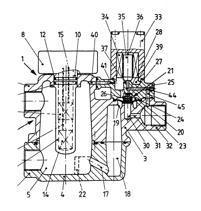
The device l illustrated in Figure l for discharginy
condensate from pressurised systems, such as compressed
air or compressed gas systems, has a housing 2 with an
upper part 3 and a lower part ~ and defining a
collecting chamber 5 for condensate. The upper part 3
is provided with a connecting piece 6 and the lower
part with a connecting piece 7, which both open into
the collecting chamber 5 and serve for incorporating
the device in a pressurised system, not shown.
Normally the connecting piece 6 is used as an inlet so
2~$~72
that the connecting piece 7 is closed off by means of a
plug or cap, tnot shown) but it i5 also possible to
employ the connecting piece 7 for the inlet. In that
case an air feeding a~d venting pipe is connected to
S the piece 6. This is led back to the same pressure
potential from which the condensate is bled.
Mounted on the upper face of the upper part 3 is an
electronic control unit 8 which has a measuring sensing
tube projecting vertically downwards into the
collecting chamber 5 from above and having its lower
end closed, the tube having a cylindrical body of
electrically non-conducting material (e.g. plastics or
ceramic) which projects into the collecting chamber 5
through a mounting flange 11 in the upper part 3 of the
housing 2 and is sealed with respect to the flange 11
by sealing rings 12.
Arranged spaced apart one above the other in the tube 9
are two capacitive sensors 13,14 which are each
electrically connected through electric leads 15 and 16
to the electronic control unit 8; thus the condensate
level in the chamber is determined electronically by
capacitive means, entirely without wear. The upper
sensor 13 serves to cletermine the highest permissible
level of the condensate in the chamber 5, whilst the
lower sensor 14 gives an indication of a lower level,
related to the of the minimum permitted level,so that
the electronic control unit 8 can produce the required
control signals for opening and closing the outlet
valve.
-
The collecting chamber 5 is connected through a
downwardly inclined passage 17 to an outlet chamber 18
which has at i-ts upper end an opening 19 leading into
the chamber 20 of a diaphragm valve 21.
2~3372
No particles of dirt or debris can be sucked up from
the floor of the collecting chamber 5 as the entry
point of the outlet passage 17 lies at a highe. level.
If the opening of the passage 17 lies at a lower level
and the outlet takes place not through an outlet
chamber 18 but through a riser pipe 47 (as illustrated
in Figure 3), a weir 22, baffle plate or wall can be
arranged ahead of the of the inlet end of the passage
or. the riser pipe in order to prevent impurities
deposited on the floor of the collecting chamber being
stirred up on discharge of the condensate from the
chamber and being carried out with the condensate or
with following compressed gas or air, which could block
up the outlet passage and/or the diaphragm valve 21 or
otherwise adversely affect its functioning.
The diaphragm valve 21 has a flexible diaphragm 23 of
which the outer periphery 2~ is clamped between the
upper part 3 of the housing 2 and an extension piece 25
secured on the upper part 3. The diaphragm is located
by a centrally arranged sleeve 26 guided to slide in a
blind hole 27 in the extension piece 25. A coil
spring 28 in the sleeve 26 and abutting against the end
of the blind hole 27 urges the diaphragm 23 downwards.
To lift the diaphragm 23 from the valve seating 29 in
the position shown in Figure 2 the force of the
spring 28 must be overcome.
A blind bore 30 in the upper part 3 extends downwards
from the valve seating 29 and leads via a transverse
bore 3~ into an outlet connection 32. A discharge
pipe, not shown, can be connected to the outlet
connection 32. Atmospheric pressure prevails in the
outlet connection 32 whereas in the collecting
- 2 ~ 3 7 2
chamber 5 the above-atmospheric pressure of the
pressurised system is main-tained during operation.
A solenoid 33 having a winding 34 and an armature 35 is
mounted on the extension piece 25. A compression
spring 36 engages the upper end of the armature 35 and
urges it downwards against the extension piece 25.
The solenoid 33 is actuated from the control unit 8.
When an electric current passes through the winding 34
it pulls the armature 35 in so that the armature is
raised to the position illustrated in Figure 2. With
the winding 34 de-energised the armature 35 lies in the
position illustrated in Figure 1 in which it engages a
seating 37 on the extension piece 25, being urged
against it by the spring 36 and by the pressure
prevailing in a control chamber 39.
The solenoid 33 forms together with the armature 35 and
seating 37 a pilot valve 38 by means of which the
diaphragm valve 21 is actuated.
Between the solenoid 33 and the extension piece 25 is
the chamber 39 into which a passage 40 leads from the
upper end of the collecting chamber 5. This passage is
straight and smooth, i.e. the internal surface which
defines the passage has neither corners nor ledges on
which, for example contamination could lodge. That
end 41 of the passage 40 which opens into the chamber
39 is narrowed or tapered in the manner of a venturi
nozzle. The transition between that end 41 which is
formed like a venturi nozzle and the remainder of the
passage 40 likewise has no projections, corners or
ledges.
;tM~ 3 7 2
The chamber 39 is in communication through a vertical
passage 42 with the chamber 20 at the upper side of the
diaphragm valve 21 so that the pressure which prevails
in the chamber 39 also acts on the upper face of the
diaphragm 23. In the seating 37 of the extension piece
25 there is a central bore 43 which communicates with
the outlet connection 32 through two mutually
connecting passages 44, 45.
The device illustrated in figure l and 2
operates in the following manner:
Under normal conditions the individual components o~
the device l are in the positions illustrated in Figure
1. The above-atmospheric pressure in the pressurised
system to which the device is connected prevails in the
collecting chamber 5. This pressure prevails also in
the outlet chamber 18, this being because of the
connection through the passage 17, and in the chamber
39, which communicates with the collecting chamber
5.through the permanently open control passage 40
Accordingly the pressure acts also on the upper face of
the diaphragm 23 because the passage 42 forms a
permanently open connection from the chamber 39 to the
chamber 20 behind the cliaphragm valve 21. The
diaphragm 23 is therefore pressed firmly onto its
seating 29, assisted by the coil spring 28. The
solenoid 33 is de-energised so the armature 35 engages
its seating 37 and it is pressed down onto it by the
pressure, assisted by the spring 36. Both valves 21,
3a are closed and so any condensate reaching the
chamber 5 from the pressurised system is collected
there.
Condensate in the housing 2 collects in the collecting
chamber 5 through the inlet connection piece 6 or 7.
2~337~
11
When the liquid level of the condensate in the chamber
5 rises to the maximum height so that the capacitive
sensor 13 in the tube 9 sends an electrical signal to
the control unit 8, the latter delivers a control
signal which energises the solenoid 33. This pulls in
the armature 35, lifting it off its seating 37 and it
is held in the position shown in Figure 2. This
uncovers the bore 43, resulting in communication
between the chamber 39 and the outlet connection 32.
As above-atmospheric pressure is present in the chamber
39, but atmospheric pressure in the outlet spigot 32,
air or gas flo~ls from the chamber 39 i.nto the outlet
connection 32, and so the pressure in the chamber 39
and thereby also the pressure acting on the upper face
of the diaphragm 23, falls. It is true that some:air
or gas does flow from the chamber 5 through the passage
40, but this cannot balance the fall in pressure in the
chamber 39 because the cross-section of the bore 43 lS
chosen to be substantially larger than the
cross-section at the reduced end 41 of the passage
40. The above-atmospheric pressure in the collecting
chamber 5 is still acting on the underside o~ the
diaphragm 43, which now causes the diaphragm 23 to be
lifted from its seating 29. Condensate flows through
the opening l9 via the outlet chamber 18 into the
chamber 20 and from this through the bore 30, 31, into
the outlet connection 32.
The arrangement is chosen to be such that the pressure
in the chamber 39 is lower than the pressure acting on
the underside of the diaphragm 23 as long as the pilot
valve 38 is open and the armature 35 is lifted clear of
its seating 37; the diaphragm valve 21 remains open as
long as the pilot valve 38 is open, and during this
time the pilot valve has compressed air or gas flowing
through it and thereby .lushing it through.
.
3 ~
On expiry of the predetermined opening time of the
diaphragm valve 21 the control unit 8 delivers a signal
causing the solenoid 33 to be de-energised. This
causes the axmature 35 to drop onto the seating 37 and
it is also pressed down by the spring 36; the bore 43
is now closed. By virtue of the gas or air
continuing to flow through the passage ~0 from the
chamber 5 pressure is built up again in the chamber 39
until it reaches the same pressure as that in the
collecting chamber 5. This pressure acts through the
connecting via the passage 42 again on the upper face
of the diaphragm 23 so that, assisted by the spring 28,
it urges the diaphragm 23 into the closed position
shown in Figure 1. Then no more gas or air or
condensate can then flow out of the collecting chamber
5 until the pilot valve 38 is opened once again.
Preferably the time interval between production of the
maximum level signal from the first sensor 13 and the
lower level signal from the sensor 14 is determined in
the electronic control unit 8. When the lower level is
reached, no control signal is yet issued to close the
outlet valve 21 again. On the contrary the measured
time interval is multiplied in the unit 8 by a factor
which is obtained from the relationship of the height
between minimum and maximum and that between minimum
and the lowest desired level in the collectin~ chamber
5. It is in this way that the overall duration of the
opening time of the diaphragm valve 21 is determined.
When this time runs out the electronic measuring unit 8
delivers the closing signal, and the condensate is then
at a level significantly below that of the lower sensor
14. Alternatively, as explained earlier, the valve
could be kept open long enough to discharge all the
condensate and then follow this with a brief blast of
gas or air.
2 ~ 3 P~' ~
The device 46 illustrated in Figure 3 largely follows
in its construction and manner of operation the device
illustrated in Figure 1 and Figure 2. Accordingly the
same parts have been given the same reference numerals
and are not described further in the following so at to
avoid repetition.
The most important difference lies in the fact that for
conducting the condensate out of the collecting chamber
5 a riser pipe 47 is arranged on the upper part 3 of
the housing 2 and is inserted in a blind hole 48. The
hole 48 leads through an opening 49 into the chamber 20
of the diaphragm valve 21.
An upstanding weir 51 is formed on the floor 50 of
the lower part 4, projecting into the interior of the
collecting chamber 5 and defining a well into which the
lower end 52 of the pipe 5 projects.
Dirt 53 can collect on the floor 50 of the lower part 4
outside the weir 51 which forms a kind of trough or
well, and the dirt can be blown out from time to time
through a connection 54 by means of a cock 55 actuated
for example by hand, before it can rise to the level of
the connecting piece 7.
Figure 3 also shows how the upper part 3 and the lower
part 4 of the housing 2 can be detachably secured
together by threaded bolts 56 and nuts 57 inserked
through mutually engaging flanges 58, 59.
If a predetermined time interval, e.g. sixty seconds,
after the first (maximum) signal has been received the
second (minimum) signal, triggered by the lower sensor,
has still not been received, then a so-called alarm
control is initiated by the electronic control unit 8
~$~37~
14
and the pilot valve 38 is closed anyway. As long as
this alarm condition prevails, it is arranged that the
valve 38 is opened for five seconds every four minutes.