Language selection

Search

Patent 2013773 Summary

Third-party information liability

Some of the information on this Web page has been provided by external sources. The Government of Canada is not responsible for the accuracy, reliability or currency of the information supplied by external sources. Users wishing to rely upon this information should consult directly with the source of the information. Content provided by external sources is not subject to official languages, privacy and accessibility requirements.

Claims and Abstract availability

Any discrepancies in the text and image of the Claims and Abstract are due to differing posting times. Text of the Claims and Abstract are posted:

  • At the time the application is open to public inspection;
  • At the time of issue of the patent (grant).
(12) Patent Application: (11) CA 2013773
(54) English Title: EARTH ANCHORING DEVICE
(54) French Title: DISPOSITIF D'ANCRAGE AU SOL
Status: Dead
Bibliographic Data
(52) Canadian Patent Classification (CPC):
  • 20/117.8
(51) International Patent Classification (IPC):
  • E04H 17/22 (2006.01)
  • E02D 5/80 (2006.01)
(72) Inventors :
  • PILDYSH, MIKHAIL (Canada)
(73) Owners :
  • PILDYSH, MIKHAIL (Canada)
  • ANCHOR ENVIRONMENTAL LTD. (Canada)
(71) Applicants :
  • PILDYSH, MIKHAIL (Canada)
(74) Agent: DUNSMUIR, GEORGE H.
(74) Associate agent:
(45) Issued:
(22) Filed Date: 1990-04-03
(41) Open to Public Inspection: 1991-10-03
Examination requested: 1991-06-25
Availability of licence: N/A
(25) Language of filing: English

Patent Cooperation Treaty (PCT): No

(30) Application Priority Data: None

Abstracts

English Abstract


ABSTRACT OF THE DISCLOSURE
One form of conventional earth anchor device
includes an anchor which is driven into the ground as the
leading element of a combination. Thus, the anchor must be
streamlined to facilitate ground entry which is incompatible
with the need for a curved body facilitating anchoring.
Another problem is the need for anchors having large bearing
areas which require considerable effort for insertion into the
ground. A device providing a solution to these problems
includes a tube or sleeve with a sacrificial blade releasably
mounted in the bottom end thereof for driving into the ground,
and a rod carrying an anchor and a spring biasing the anchor
outwardly, whereby the sleeve can be driven into the ground,
following which the rod is held down while the sleeve is
extracted, leaving the blade, and, when the anchor and spring
exit the sleeve, the spring biases the anchor into a ground
engaging position. An upward pull on the rod pivots the
anchor into a secure anchoring position in the ground.


Claims

Note: Claims are shown in the official language in which they were submitted.


THE EMBODIMENTS OF THE INVENTION IN WHICH AN EXCLUSIVE
PROPERTY OR PRIVILEGE IS CLAIMED ARE DEFINED AS FOLLOWS:

1. An anchor device comprising sleeve means for
hammering into the ground; blade means releasably mounted in
the bottom end of said sleeve means for facilitation entry of
the device into the ground; rod means for insertion into and
removal from said sleeve means; elongated plate means,
including a center portion extending across and pivotally
mounted on said rod means, an upper, resilient leg extending
outwardly and upwardly from said center portion on one side
of said rod means; and a lower resilient leg extending
outwardly and downwardly from the center portion on the other
side of said rod means for rotation around a horizontal axis,
said anchor means being slidable in said sleeve means with
said rod means when then rod means and anchor means are
inserted therein, whereby, when the sleeve means carrying the
remainder of the device is hammered into the ground and then
extracted while the rod means is held down against the blade
means, the spring means biases the anchor means into a ground
engaging position.
2. A device according to claim 1, wherein said lower
leg of said anchor means extends outwardly and downwardly,
and then inwardly toward said rod means.


3. A device according to claim 2, wherein said lower
leg includes slot means extending upwardly from the bottom
free edge thereof for receiving said rod means, whereby said
lower leg overlaps the rod means when the anchor means is in
said sleeve means.
1. A device according to claim 1, wherein said spring
means is a generally inverted L-shaped leaf spring including
a horizontal arm on said rod means and a vertical arm
extending downwardly between said rod means and said lower
leg of said rod means.
5. A device according to claim 3, wherein said upper
leg means includes teeth on the upper free end thereof for
digging into the ground.
6. A device according to claim 5, wherein said anchor
means includes reinforcing means extending along at least
said upper and lower leg means.
7. A device according to claim 6, wherein said
reinforcing means includes corrugations extending
longitudinally of said anchor means.


Description

Note: Descriptions are shown in the official language in which they were submitted.


~3773

This invention relates to an earth or ground anchor
device, and in particular to a device of the type which is
used to hold a guy wire or the like. --
Earth anchors of the type proposed herein, i.e.
employing the same concept as the present invention, have been
in existence for some time. Examples of such anchors are ~`
described in Canadian Patent No. 1,045,331, which issued to ``
R.F. Deike on January 2, 1979, and in United States Patent No. ` ~
4,096,673, which issued to R.F. Deike on June 27, 1978. `
In general, existing ground anchors have significant
disadvantages. One such disadvantage is the anchoring ability ~; ~
of the device which is dictated by the size of the anchor. In ;
soft soil, larger bearing areas are required; otherwise, the -
bearing capacity of the soil around the anchor is exceeded,
causing release of the anchor. Large anchors cause insertion
problems, because a substantial effort is required to drive
the anchors into the ground. Another disadvantage of existing
anchor devices is that such devices are driven into the ground
anchor first, i.e. with the anchor at the bottom, penetrating
end of the device. In order to maximize the anchoring
capacity, the device should be curved. This need is
incompatible with the streamlined shape required for driving a
pointed article into the ground. Attempts to effect a
trade-off between the two requirements has resulted in
anchoring devices which are deficient in terms of anchoring
ability and/or ease of insertion into the ground.


'';"~'' - `I '
:: , - ~ :
. . . :
., -, : :

2~3773 : ~
, :
An object of the present invention is to overcome ;~
the above-identified problems by providing a relatively simple
anchoring device which is easy to lnsert into the ground,
regardless of soil conditions.
1 5 Another object of the invention is to provide an -
¦ anchoring device which may include one or more anchors for
simultaneous insertion into the ground as required by soil
conditions.
Accordingly, the present invention relates to an
earth anchor device comprising sleeve means for hammering into `~
the ground; blade means releasably mounted in the bottom end
of said sleeve means for facilitating entry of the device into
the ground; rod means for insertion into and removal from said
sleeve means; anchor means pivotally mounted on said rod means
for rotation around a horizontal axis, said anchor means being
slidable in said sleeve means with said rod means; and spring
means on said rod means biasing said anchor means outwardly
against said sleeve means when the rod means and anchor means
are inserted therein, whereby, when the sleeve means carrying ; -;
the remainder of the device is hammered into the ground and
then extracted while the rod means is held down against the
blade means, the spring means biases the anchor means into a
ground engaging position.
The invention will be described in greater detail
with reference to the accompanying drawings, which illustrate
a prepared embodiment of the invention, and wherein:


; 2~773 ~:

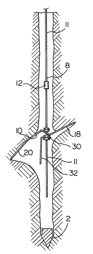
Figures 1 and 2 are longitudinal sectional views, at
~,j right angles to each other, cf an anchor device in accordance
with the present invention;
Figure 3 is a longitudinal sectional view of a rod
and anchor used in the device of Figs. 1 and 2; `~
Figure 4 is a front elevational view of the anchor
of Fig. 3; and
Figures 5 and 6 are longitudinal sectional views of `~
a hole in the ground with the device of the present invention
7 10 therein;
With reference to Figs. 1 and 2, the anchor device
of the present invention includes an elongated metal sleeve 1
of rectangular cross section. A blade 2 with a pointed bottom
¦ end 3 is releasably mounted in the bottom end of the sleeve 1facilitating hammering of the sleeve into the ground. The
top end 6 of the blade has a reduced diameter for insertion
into the bottom end 4 of the sleeve 1. A shoulder 7 at the
j bottom end of the reduced diameter portion 6 preventing the
entry of material into the sleeve 1 when the device is
hammered into the ground. A rod 8 carrying an anchor body 10
is slidably mounted in the sleeve 1. As suggested by the ;
phantom outlines in Figs. 1 and 2, the rod 8 can carry more
than one anchor 10. The rod 8 is defined by a plurality of
threaded sections 11 interconnected by internally threaded
couplers 12. When the anchor is being embedded a short


. - . , .

`~,` ~ ~ ' , :

,`' ~ . ` ' ' ' ~

2~L37~3
.~ .
~istance in the ground, a single elongated, threaded rod
section 11 can be used.
As best shown in Figs. 3 and 4, the anchor 10 is ;
defined by an elongated strip of metal with a slot 14 in the ~ ~
center thereof for pivotally mounting the anchor on the rod 8. ~ -
The anchor 10 is maintained on the rod 8 by top and bottom
nuts 15 and 16, respectively. The anchor 10 is defined by an --
upper leg 18 on one side of the rod 8, a centre section or
portion 19 containing the slot 14 and straddling the rod 8,
and a lower leg 20 extending outwardly and downwardly from the ~ `
other side of the rod 8. The lower leg 20 includes an
elongated central slot 22 extending upwardly from the bottom
edge 23 of the anchor 10. The bottom free end 24 of such
lower section 20 is bent into overlapping relationship with
the rod 8 beneath the nuts 16, the slot 22 straddling the rod
8. The top end 26 of the anchor 10 is sharp and serrated,
acilitating penetration of the soil. A pair of corrugations
or ribs 27 extend longitudinally of the anchor 10 for
strengthening the latter. A generally inverted L-shaped leaf
spring 29 is mounted on the rod 8. One arm 30 (Figs. 1 and 3)
of the spring 29 is sandwiched between the two lower nuts 16.
The other arm 32 of the spring extends downwardly against the
inner surface of the lower leg 20 of the anchor body 10.
In use, one or more anchors 10 are mounted on the
rod 8 and slid into the sleeve 1. When inserting the anchor
10 into the sleeve 1, it is necessary to press the legs 18 and -~


~: . :' ' . : ': : !. '

7 ~

20 towards the rod 8, deforming or tensioning the spring 29.
Thus, when the anchor 1 is located in the sleeve 1, the spring
29 biases the upper and lower legs 18 and 20, respectively of
the anchor body 10 is biased outwardly above the nuts 15 and
below the nuts 16 against the walls of the sleeve 1. The
sleeve 1 is hammered into the ground to the desired depth.
While holding the rod 8 down, the sleeve 1 is pulled out of
the ground (Fig. 5). When the anchor 10 is released by the
sleeve 1, the spring 29 presses the upper and lower legs 18
and 20, respectively outwardly against the sides of the hole.
If the rod 8 is pulled upwardly (Fig. 6) the free ends 23 and -
26 of the anchor are pressed into the soil to firmly secure
the anchor 10 in the ground. A guy wire (not shown) or other
device can be attached to the top end of the rod 8 to firmly
secure a post or other article in position.


~ ', ' ' .
.
~: . . - -

Representative Drawing
A single figure which represents the drawing illustrating the invention.
Administrative Status

For a clearer understanding of the status of the application/patent presented on this page, the site Disclaimer , as well as the definitions for Patent , Administrative Status , Maintenance Fee  and Payment History  should be consulted.

Administrative Status

Title Date
Forecasted Issue Date Unavailable
(22) Filed 1990-04-03
Examination Requested 1991-06-25
(41) Open to Public Inspection 1991-10-03
Dead Application 1994-10-03

Abandonment History

There is no abandonment history.

Payment History

Fee Type Anniversary Year Due Date Amount Paid Paid Date
Application Fee $0.00 1990-04-03
Maintenance Fee - Application - New Act 2 1992-04-03 $50.00 1992-03-17
Maintenance Fee - Application - New Act 3 1993-04-05 $50.00 1993-03-26
Registration of a document - section 124 $0.00 1994-01-07
Owners on Record

Note: Records showing the ownership history in alphabetical order.

Current Owners on Record
PILDYSH, MIKHAIL
ANCHOR ENVIRONMENTAL LTD.
Past Owners on Record
None
Past Owners that do not appear in the "Owners on Record" listing will appear in other documentation within the application.
Documents

To view selected files, please enter reCAPTCHA code :


To view images, click a link in the Document Description column. To download the documents, select one or more checkboxes in the first column and then click the "Download Selected in PDF format (Zip Archive)" or the "Download Selected as Single PDF" button.

List of published and non-published patent-specific documents on the CPD .

If you have any difficulty accessing content, you can call the Client Service Centre at 1-866-997-1936 or send them an e-mail at CIPO Client Service Centre.


Document
Description 
Date
(yyyy-mm-dd) 
Number of pages   Size of Image (KB) 
Cover Page 1991-10-03 1 34
Abstract 1991-10-03 1 36
Claims 1991-10-03 2 89
Drawings 1991-10-03 3 145
Description 1991-10-03 5 219
Representative Drawing 1998-07-22 1 13
Correspondence 1991-10-02 1 40
Fees 1992-03-17 1 28
Fees 1993-03-26 1 46