Language selection

Search

Patent 2013777 Summary

Third-party information liability

Some of the information on this Web page has been provided by external sources. The Government of Canada is not responsible for the accuracy, reliability or currency of the information supplied by external sources. Users wishing to rely upon this information should consult directly with the source of the information. Content provided by external sources is not subject to official languages, privacy and accessibility requirements.

Claims and Abstract availability

Any discrepancies in the text and image of the Claims and Abstract are due to differing posting times. Text of the Claims and Abstract are posted:

  • At the time the application is open to public inspection;
  • At the time of issue of the patent (grant).
(12) Patent Application: (11) CA 2013777
(54) English Title: REMOVABLE FRICTION REDUCING TREAD FOR ALL TERRAIN BICYCLE TIRES
(54) French Title: SEMELLE DE ROULEMENT REDUCTRICE DE FROTTEMENT ET AMOVIBLE POUR PNEUS DE BICYCLETTES DE MONTAGNE
Status: Dead
Bibliographic Data
Abstracts

English Abstract


ABSTRACT OF PATENT
REMOVABLE FRICTION REDUCING TREAD
FOR ALL TERRAIN BICYCLE TIRES
The tires of an all terrain bicycle (ATB) are converted from being
wide, soft and covered with knobs as required for traction in dirt
tires which are narrow, hard and smooth so as to greatly reduce the
ATBs rolling friction over pavement. Installing this invention when
appropriate allows the ATB to efficiently serve both for recreational
purposes and commuting purposes. The invention takes the form of
a removable hoop who's inside diameter is slightly smaller than the
outside diameter of a standard ATB tire. It is attached to the ATB
tire utilizing friction resulting from de-flating the ATB tire, forcing
the tread hoop onto its center and then re-inflating the tire. The
hoop itself is composed of two elements. The first is an inner band
made of steel, carbon fiber or other material having high rigidity and
tensile strength. This band provides tensile strength in the hoop,
distributes the load from the hoop onto multiple knobs on the ATB
tire and also keeps the hoop circular despite the widely spaced knobs
supporting it. The second component of the rubber hoop is the
rubber itself which forms the low friction tread and inside of which
the tensile band is encased. The rubber component is roughly semi-
circular in cross section and has the tensile band cast within it near
its slightly concave inner side. The convex outer surface of the
rubber component has a shallow road racing tread pattern cast into
it.


Claims

Note: Claims are shown in the official language in which they were submitted.

CLAIMS
The embodiments of the invention in which an exclusive property or
privilege is claimed are defined as follows:
1) A removable treaded hoop to be attached to the tread of a
standard ATB tire reducing it's area of contact with the ground as
well as reducing the irregular bumpiness of the ATB tread at this
contact area and thus reducing the ATB tires rolling friction when
traversing pavement.
2) An apparatus as defined in claim 1 in which the hoop is
constructed so as to be affixed concentrically to the ATB tire by
means of friction resulting from pneumatic expansion of the ATB tire.
3) An apparatus as defined in claim 1 or claim 2 or claim 3 in which
the hoop is comprised of two concentric structural components; one
imparting to the hoop low rolling friction while the other component
imparts tensile strength and rigidity.
4) An apparatus as defined in claim 1 or claim 2 in which installation
of the hoop increases the overall gear ratio of the ATB.
5) An apparatus as defined in claim 1 or claim 2 or claim 3 or claim 4
in which the protrusion of the low friction tread hoop above the
underlying ATB tread is narrow enough to allow some underlying
tread exposure which can still provide some flotation and traction if
the low friction hoop sinks into soft terrain.


Description

Note: Descriptions are shown in the official language in which they were submitted.


f r~ ~

DISCLOSURE
This invention relates to the tires of bicycles intended for use in
rough or soft terrain, specifically the modification of said tires to
enable them to roll with low resistance when operated over
pavement.
In order to obtain sufficient traction in sand and mud, the tires of All
Terrain Bicycles (ATBs) require a wicle ~ire tread covered with large
knobs. They are designed to operate at low pneumatic pressures so
as to flaten and contact the ground over a large area and ~Iso so as to
absorb shocks before they reach the r;der. While these tires can bite
into soft terrain for needed traction they have the drawback of
producing high rolling resistance and noise when used on pavement
Due to this high rolling resistance, riders wishing to use their ATB for
commuting in the city suffer unnecessary fatigue
To obtain efficient pedaling in both city and wilderness
environments the rider must currently purehase two bicycles, each
designed in large measure to accept the tires best adapted for each
environment. A cheaper alternative is to mount special slick ATB
tires on the ATB rims when the rider wishes to commute over
pavement and then re-mount the conventional ATB tires when
wilderness recreation is the object. This option is relatively
inexpensive however the work involved in repeatedly changing tires
is prohibitive and the large slick tires when fitted to the ATB rims
for commuting still have a large contact area with the road and hence
a high rolling resistance.
The above limitations and disadvantages can be overcome by using
my invention which quickly and inexpensively coverts an existing
ATB tire into one possessing the rolling friction characteristics of a
high pressure road-racing tire.
When mounted onto the ATB tire, the solid composite hoop described
herein acts as a buffer between the ATB tire and the road. Once the
rubber and metal tread hoop is mounted on the ATB tire, the surface
area that is in contact with the road is greatly reduced and this
contact area is much harder and smoother than that of a standard
ATB tire. This lowers the rolling resistance on pavement, thus
enabling the rider to travel faster for any given level of pedaling
effort. Additional benefits are reduction of tire noise and rendering
the tires impervious to punctures.


," ,-,. . . . .
,., ~ ~ .
.... :~ :
. . .
~.,,, ~ :

3777

Since the solid tread hoop is slightly flexible ~md is itself swpported
by the relatively soft ATB pneumatic ~ire, the rider benefits from a
smoother ride over cracks and bumps in the pavement than if an
equally hard road tire were mounted directly onto the ATBs wheel
rims.
Since the removable friction reducing tread is signi-ficantly narrower
than the underlying ATB tread, some traction knobs on the ATB
tread are still left exposed. This perrnits the rider to enjoy the
benefits of low friction when riding on pavement and yet retain
some degree of traction in soft terrain. If the rider wishes to
traverse some sections of soft terrain such as mud, sand or snow, the
smooth friction reducing hoop will sink into the soft terrain far
enough that the ATB knobs on each side of it will gain a purchase in
the terrain and thus allow some degree of flotation and traction.
When the removable friction reducing treads are mounted for
commuting on pavement, the thickness of the tread hoop adds
approximately one inch to the diameter of the ATB wheels. The
increased wheel diameter has the effect of raising the overall gear
ratio of the ATBs transmission. Since standard ATBs are geared for
low speed climbing torque this higher gear ratio will automa~ically
allow the rider to make better use of the higher speed potential that
the lowered rolling friction presents.


'.~

In drawings which illustrate embodiments of the invention;
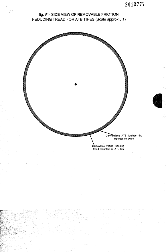
Figure I is a side view of a complete ATB wheel indicating the
concentric fashion in which the invention is affixed to the ATB tire.
Figure 2 is a cross sectional view of the removable tread including
the ATB tire on which it's mounted and their relation to the road
surface.
Figure 3 is a blow-up of figure 2 showing the internal construction of
the hoop itself.
The invention takes the form of a relmovable hoop who's inside
diameter is slightly smaller than the nominal outside diameter of an
ATB tire. It is attached to each bicycle wheel concentrically as
illustrated in figure 1 It is affixed to the ATB tire utilizing friction
resulting from de-flating the tire, forcing the hoop onto its center and
then re-inflating it. Figure 2 illustrates how the tread hoop is
supported by the ATB tire and how it smooths and reduces the tires
contact area with the road so as to reduce the rolling fiiction.
The hoop itself is composed of two elements as shown in figure 3
The first is an inner band made of steel, carbon fiber or other
material having high rigidity and tensile strength This band
performs three functions;
l-It provides the tensile strength within in the hoop necessary to
fully constrain the inflation of the ATB tire and thus achieve a tight
friction mounting.
2-It distributes the load from the hoop onto multiple knobs on the
ATB tire.
3-On smooth pavement it keeps the hoop very circular despite the
widely spaced knobs supporting it. This minimizes the tires contact
area with the road.
The tensile bands cross section may be flat, corrugated or a more
complex structural extrusion in order to attain the desired hoop
rigidity. The surface of ~he tensile band may be smooth, textured or
perforated in order to attain adequate bonding to the surrounding
material.
The second element of the tread hoop is the rubber material itself
inside of which the tensile band is encased. This rubber hoop is
roughly semi-circular in cross section. It may have some complex


,",' ~ . . , i ' ' '
~,
~., ~ , ,
. ' ~

'"';~ " ' ' ' ' `

2~137'77

curved segments in order to achieve adequate road adhesion and
clearance It has the tensile band cast within it near its slightly
concave Inner side. This slightly concave inner surface allows the
hoop to more easily achieve firm contact with the convex crown of
the ATB tire as the tire is re-inflated, This concave inner surface
may be textured or covered with a h;gher adhesion material than the
tread rubber itself in order to improve the hoops friction bond to the
ATB tire. The convex outer surface of the hoop has a shallow, low
friction road-racing tread pattern cast into it which may be
comprised of both transverse and lvngitudinal ridges and grooves,
The flexibility of the two materials usled in the hoop and their
structural relationship are engineered such that under smooth road
conditions the hoop remains rigid enough so as to maintain a
minimal contact area with the road surface. However, when a road
imperfection is encountered the the hoop materials will yield
somewhat under the shock and thus transmit some of the energy
into the lower part of the relatively soft ATB tire, The pneumatic
ATB tire will in turn absorb some of this shock and thus prevent it
from being transmitted to the rider,


f ~
~ ~ .

.. .
, . . .
, .~, . . .
, .. . ..

Representative Drawing
A single figure which represents the drawing illustrating the invention.
Administrative Status

For a clearer understanding of the status of the application/patent presented on this page, the site Disclaimer , as well as the definitions for Patent , Administrative Status , Maintenance Fee  and Payment History  should be consulted.

Administrative Status

Title Date
Forecasted Issue Date Unavailable
(22) Filed 1990-04-04
(41) Open to Public Inspection 1991-10-04
Dead Application 1992-10-05

Abandonment History

There is no abandonment history.

Payment History

Fee Type Anniversary Year Due Date Amount Paid Paid Date
Application Fee $0.00 1990-04-04
Owners on Record

Note: Records showing the ownership history in alphabetical order.

Current Owners on Record
KIELLAND, PETER J.
Past Owners on Record
None
Past Owners that do not appear in the "Owners on Record" listing will appear in other documentation within the application.
Documents

To view selected files, please enter reCAPTCHA code :


To view images, click a link in the Document Description column. To download the documents, select one or more checkboxes in the first column and then click the "Download Selected in PDF format (Zip Archive)" or the "Download Selected as Single PDF" button.

List of published and non-published patent-specific documents on the CPD .

If you have any difficulty accessing content, you can call the Client Service Centre at 1-866-997-1936 or send them an e-mail at CIPO Client Service Centre.


Document
Description 
Date
(yyyy-mm-dd) 
Number of pages   Size of Image (KB) 
Representative Drawing 1999-07-19 1 4
Cover Page 1991-10-04 1 61
Abstract 1991-10-04 1 50
Claims 1991-10-04 1 42
Drawings 1991-10-04 2 78
Description 1991-10-04 4 207