Note: Descriptions are shown in the official language in which they were submitted.
2~ 38~
_ 203-214
- I (1102)
. ~
1 LOCKING MECHANISM FOR A SURGICAL FASTENING APPARATUS
BACKGROUND OF THE INVENTION
1. Field of the Invention
This invention relates to surgical fastening
apparatus, and specifically to an improved surgical
fastening apparatus containing a locking means.
2. Background of the Prior Art
Surgical fastening apparatus for placing gastro
intestinal anastomoses are known in the art. Such apparatus
are used for suturing gastric and intestinal walls with
spaced parallel rows of longitudinally aligned staples or
surgical fasteners. For example, Bobrov et al. (U.S. Patent
No. 3,079,606) discloses an instrument for suturing gastric
and intestinal walls with metal staples by inserting the tips
of the instrument into the lumens of the organs to be
sutured through apertures in the walls of the organs. The
apparatus comprises a two part frame, each part having
finger like projections or forks which are inserted
respectively into the apertures in the walls of the organs
to be sutured. The frame parts are hinged together with the
body tissue held between the forks. When the instrument is
actuated, longitudinally moving cam bars contact staple
drive members in one of the forks, thereby pushing the
surgical staples through the body tissue and into an anvil
in the opposite fork. A knife blade between the cam bars
creates an incision between the parallel rows of staples.
It should be noted, however, that the knife blade is an
optional feature. The instrument may be used to fasten body
3o tissue without creating an incision between the rows of
staples.
~L
,~
` -2- 20 1 38~2
1 Green et al. (U.S. Patent No. 3,490,675) discloses
an improved instrument of type discussed above, the improved
instrument laying down double rows of staples on each side
of the incision.
A further improvement in this type of instrument
is disclosed in Green (U.S. Patsnt No. 3,499,591). The
- further improved apparatus incorporates an improved
structure for the staple-containing cartridge, the pusher
assembly which includes the cam bars and knife, and the
staple driving members.
Generally, the instruments discussed above are
successfully used in abdominal, gynecological, pediatric and
thoracic surgery for resection, transection and creation of
anastomoses. However, there is a danger during an operation
that the surgeon may inadvertently insert the forks of the
instrument into body organs when the instrument is empty of
staples. This can occur when the instrument has already been
fired but not reloaded or discarded. Under such
circumstances, the cam bar and knife blade can be moved,
thereby creating an unsealed incision, and causing blood
loss and trauma to the patient undergoing the surgery.
Non-cutting fasteners, i.e., those without the optional
knife mechanism, are also commonly used to seal incisions,
for example, in transactions in which the surgeon uses a
scalpel to manually create an incision on the outside of the
rows of staples. Consequently, the danger of using an empty
fastener applies equally to both cutting and non-cutting
fasteners. The surgical fastsning apparatus
2~ 8~;~
1 mentioned above do not possess means for preventing the
problem of reactuation of an apparatus which is empty of
staples.
To eliminate these dangers it is beneficial to
have a locking mech~nism which will allow a single use, but
which will prevent the surgical stapler from being
inadvertently fired more than once.
SUMMARY OF THE lN v~ ON
Accordingly, it is one object of the present
invention to provide a surgical fastening apparatus.
It is another object of the present invention to
provide an improved surgical fastening apparatus having a
locking mechanism for preventing reactuation of the
apparatus.
These and further objects are achieved herein by
providing a surgical fastening apparatus including a single
use locking mec-hanism to prevent reactuation of the surgical
fastening apparatus, said surgical fastening apparatus
comprising:
a) a frame;
b) a stationary carrier receivable into said
frame;
c) a pusher assembly slidably mounted within said
stationary carrier, said pusher assembly comprising at least
one cam bar, a cam bar retainer for mounting the cam bar,
6aid cam bar retainer having a locking notch, a thrust knob
attached to the cam bar retainer and optionally a knife
mounted to the cam bar retainer;
d) a resilient locking clip fixed to the
stationary carrier and having a hook, said locking clip
being adapted to be resiliently urged from a first position
-4- 2~8~2
1 wherein said hook is non-engagable with said locking notch,
to a second position wherein said hook is engagable with
said locking notch; and,
e) a blocking means, adapted to be movable from a
location wherein said blocking means holds said locking clip
in said non-engagable first position to a location wherein
said blocking means does not hold said locking clip in the
non-engagable first position.
BRIEF DESCRIPTION OF THE DRAWINGS
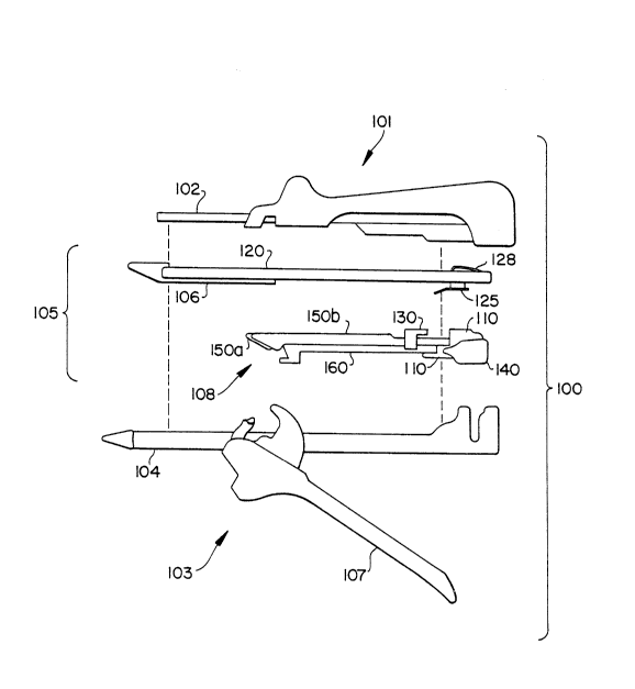
Fig. 1 illustrates an exploded side view of the
surgical fastener;
Fig. 2 illustrates the placement of the removable
carrier within the surgical fastener;
Fig. 3 illustrates the manual operation of the
surgical fastener;
Fig. 4 illustrates a cut-away perspective view of
the locking mechanism in the locked position;
Fig. 5 illustrates a side view of the lock
mechanism in the unlocked position. The arm and thrust knob
are not shown; and,
Fig. 6 illustrates a cut-away perspective view of
the locking ~C~icm. The cam bars, knife, and sliding
chock are not shown.
DETAILED DESCRIPTION OF THE lNv~NllON
Figs. 1, 2 and 3 illustrate a surgical fastening
apparatus for placing gastrointestinal anastomoses.
Surgical fastening apparatus 100 is composed of a cartridge
half of a frame 101 having a cartridge fork 102, an anvil
half of a frame 103 having an anvil fork 104 and a pivotable
ZC~38~32
1 large handle 107, and a disposable loading unit 105
comprising a cartridge assembly 106 (which carries the
surgical staples), a stationary carrier 120, and a slidable
pusher assembly 108 which includes cam bars 150a, 150b, cam
bar retainer 110, optional knife 160, chock 130 and thrust
knob 140. The disposable loading unit 105 is loaded into
the cartridge half of the frame 101 as shown in Fig. 2, the
instrument is assembled, and actuated as shown in Fig. 3
(body tissue to be fastened is not illustrated).
Figs. 4, 5 and 6 illustrate a single use locking
mechanism to prevent reactuation of the surgical stapling
apparatus. Stationary carrier 120 is an elongated metal
piece having a substantially U-shaped cross section with a
base 122 and sidewalls 121a and 121b. Stationary carrier
120 is adapted to fit into a surgical stapler as shown in
Figs. 1, 2 and 3. At its proximal end, stationary carrier
120 has a backflap 123 to prevent the sliding pusher
assembly from exiting the instrument. Base 122 has an
opening 124 of generally U-shape. Tongue 6haped resilient
spring clip 128 is attached at its proximal end to base 122
and defines the inner perimeter of the opening 124. Clip
128 is optimally an integral part of the carrier 120. Hook
129 at the distal end of resilient clip 128 curves back in
the proximal direction. Optimally, clip 128 is a planar
strip which is resiliently bendable in a direction
transverse to its plane. Stationary carrier 120 also has a
catch plate 125 with guide slope 127 and, as shown in Fig.
5, an aperture 126 for engaging circular detent 116 as
explained below.
The surgical fastening apparatus of the present
invention also comprises a slidable pusher assembly located
within the stationary carrier. The slidable pusher assembly
-6- ~ 8~2
1 is composed of one or more cam bars 150a, 150b, optionally a
knife 160, a cam bar (and knife) retainer 110, and a thrust
knob 140. When the instrument i8 actuated the cam bars will
be longitudinally moved through a cartridge assembly,
thereby firing the staples.
Cam bar retainer 110 is a solid member, preferably
constructed of a strong polymeric resin, which serves as a
mounting for the cam bars 150a and 150b and knife 160. Slot
112a in the cam bar retainer receives cam bar 150a, slot
112b receives cam bar 150b, and 810t 113 receives knife 160.
Cam bar retainer 110 has a horizontal locking notch 111 at
its distal end for engaging hook 129. Large and small
shoulders, 118 and 117 ride longitudinally within stationary
carrier 120. Front face 135 of large shoulder 118 acts as a
stop when cam bar retainer 110 reaches the proximal end of
cartridge 106. Cam bar retainer 110 has a shelf 114 for
engaging the overhang 131 of the chock 130. Backslope 115
enables the cam bar retainer to be easily retracted to the
original position in the proximal end of stationary carrier
120. Cam bar retainer 110 also has a circular detent 116
which is received into aperture 126 of catch plate 125. The
detent keeps the cam bar retainer 110 secured from
accidental firing during ~hipping and handling. However,
the operating surgeon can easily override it manually when
pushing on the thrust knob. Arm 119 extends outward from
the cam bar retainer 110 and is optimally an integral piece
thereof. Thrust knob 140 is attached to arm 119 and
provides a means for manually actuating the slidable cam
aæsembly.
Chock 130 provides a blocking means to block or
bar the locking clip 128 from resiliently b~n~ ~ ng into a
position wherein hook 129 can engage locking notch 111 of
-7- ~ 8~
-
1 the cam bar retainer 110. Chock 130 i6 slidably mounted on
cam bar 150b, and has two depending legs 132a and 132b,
which define a slot 133 for riding on the cam bar 150b.
Chock 130 also has an overhang 131 adapted to engage shelf
114 of the cam bar retainer 110. The outward facing surface
of chock 130 contacts the inner surface of sidewall 121b,
particularly along the outwardly facing surface of depending
leg 132b.
The single use locking mechanism is initially in
the position as shown in Fig. 5. (The arm and thrust knob
are not shown.) The freely slidable chock 130 rests on cam
member 150b and is located under the hook 129 of resilient
clip 128. In this position hook 129 cannot engage notch 111
of the cam bar retainer 110 because the chock holds the
locking clip 128 in a position where said hook 129 is not
longitudinally aligned with the notch 111. To actuate the
instrument, the surgeon presses on the thrust knob 40 with
sufficient force to override the cooperation between d4tent
116 and catch plate 125, e.g., by shearing off detent 116 or
deflecting catch plate 125 away from detent 116. The pusher
assembly 108 slides distally in carrier 120 whereupon cam
bar retainer 110 engages chock 130 and pushes it to the
distal end of the carrier 120. A viscous lubricant on the
inside surface of sidewalls 121a and 121b facilitates the
sliding movement. The chock scrapes most of the lubricant
off the inner surface of side wall 121b as it passes,
thereby increasing the frictional resistance to returning to
its original position. When the staples are fired the
thrust knob 140 is pulled proximally and the cam bar
retainer is drawn back into the initial position. Rear
sloping surface 115 enables it to pass the resilient clip.
-8- ~8~
-
1 The chock 130 is not drawn all the way back, however, in
part because of the increased friction with side wall 121b,
and chock 130 remains in a subseguent location where it no
longer abuts locking clip 128. After cam bar retainer 110
moves proximally past clip 128, clip 128 resiliently springs
into a position in which hook 129 is engagable with notch
111. If the surgeon inadvertently attempts to reactuate the
instrument, the hook 129 and notch 111 will engage and the
cam bar retainer 110 will lock, as shown in Fig. 4.
The loading unit 105 containing the stationary
carrier 20, cartridge assembly 106, and pusher assembly 108,
is optimally disposable. After using one loading unit, the
surgeon may replace it wit~ a new loading unit. The two
part frame may be reused. However, it is also within the
scope of this invention to have an entirely disposable
apparatus in which the frame is not meant to be reused.
Generally the stationary carrier is made of metal
such as stainless steel. The cam bars and knife are also
preferably of stainless steel construction. The cam bar
retainer, chock, arm and thrust knob may be made of any
suitable high strength polymeric resin ~uch as
polycarbonate.
While the above description contains many
specifics, these specifics should not be construed as
limitations on the ~cope of the invention, but merely as
exemplifications of preferred embodiments thereof. Those
skilled in the art will envision many other possible
variations that are within the scope and spirit of the
invention as defined by the claims appended hereto.
3o