Note: Descriptions are shown in the official language in which they were submitted.
2013969
- 1 - C3246
LIOUID DISPENSING MEANS
lS
This invention relates to liquid dispensing means and
particularly to a method and means for simply and safely
dispensing products in doses from a container.
Products that could be harmful, especially in
concentrated form, or which are susceptible to
contamination eg. by water are preferably not simply
poured from an open mouth container after removing a cap.
On the one hand there is a danger of spilling and on the
other hand there is a danger of contamination by eg. water
being able to accidentally enter the open-mouth of the
container when the cap is removed.
It has been proposed in GB 2 098 958 to provide a
permanently fixed valved container closure having a
discharge aperture covered by a resilient diaphragm
openable in response to internal container pressure and
having a closing member movable to a closed position in
which contents are prevented from being discharged. An
overcap having an integral hook surrounds the container
closure in transport and distribution and is fitted to the
2013969
- 2 - C3246
opposite end of the container by the user to facllitate
dispensing the product from the container. In this
proposal there i8 a risk of spillage or contamination of
the container contents when the closing member is in the
S open position.
According to the present invention there is provided
liquid dispensing means for a container comprising a
closure of the ~ind that is permanently fixed to a
lo container neck and adapted to allow the passage of liquid
therethrough when the internal container pressure exceeds
the ambient pressure and which seals against the flow of liquid when the
internal container pressure is substantially equal to ambient pressure, a
closing member movable between an
open position in which increased internal pressure in the
container can effect liquid discharge and a closed
position in which liquid discharge is prevented, and a
removable overcap adapted to surround the closure,
characterised in that the overcap is rotatably mounted on
the container in operative engagement with the closing
member and movable between a locked position in which the
overcap is locked to the container and the closing member
is in the open position, and a releasable position in
which the overcap can be removed from the container and
2S the closing member is in the closed position.
- With the overcap locked on the container the closing
member is in the open position 80 that a desired dose of
product can be discharged into the overcap by increasing
the internal container pressure to open the closure. The
overcap is then rotated to the releasable position in
which it can be removed from the container thus moving the
closing member to the closed position in which the closure
is prevented from opening. The overcap together with its
35 contents can be used as required and whilst the overcap is
removed from the container the closure remains closed
2013969
- 3 - C3246
thereby preventing accidental spillage or contamination of
the remaining container contents.
Depending upon the amount of product to be dispensed
into the overcap it can be convenient for the overcap to
be, at least in part, sufficiently transparent for the
amount of product therein to be observed without the need
for removing the overcap from the container.
lo The size of the outlet passage through the closure
can be adapted relative to the viscosity of the liquid so
that the liquid is only discharged when the internal
container pressure is increased. The internal container
pressure can be increased by a pump device but is
preferably achieved by using a flexible container which
can be squeezed.
The closure can have an iris mechanism which is
opened and closed by movement of the closing member. Thus
when the iris mechanism is open contents can be discharged
therethrough into the overcap. Alternatively there can be
provided one or more holes in the closure and closing
member which are moved in and out of alignment to
respectively open and close the closure.
Since the closing member can only be in the open
position when the overcap is locked in place any leakage
which may occur, or discharge which may arise through
inadvertent squeezing of the container, is caught by the
overcap. Nevertheless, for liquids which are not
sufficiently viscous and to provide a more positive
cut-off of flow from the closure the closure preferably
incorporates a resilient diaphragm sealing the closure and
responsive to internal pressure in the container to open
the closure.
2013969
- 4 - C3246
The overcap can be adapted to serve as a base on
which the container can be stood during storage. Thus,
particularly when the contents of the container are a
viscous liquid, the container can be stored so that the
contents are adjacent the closure and can be immediately
discharged. It can also be particularly convenient if the
closing member provides a foot on which the container can
be stood whilst the overcap is removed therefrom.
Providing for the container to be stood in either or both
lo of these arrangements can also be convenient if the
container does not have a conventional base on which it
can stand.
The operative engagement of the overcap with the
closing member can be achieved by providing the closing
member with a non-circular foot forming skirt, the overcap
having a correspondingly shaped plug portion fitting
within the skirt to operatively engage the overcap with
the closing member. Thus rotation of the overcap relative
to the container effects rotation of the closing member to
move it between the open position and the closed position.
The closing member can comprise a closure surrounding
2 portion having a dispensing aperture therein, an outwardly
extending annular flange having arcuate slots therein and
the skirt at its periphery, support arms attached to the
closure extending through said slots and carrying lugs
which are engagable in bayonet like manner with an
30 inwardly projecting flange on the plug portion of the
overcap to lock the overcap to the container.
The bayonet engagment of the lugs with the flange on
the plug portion permit the overcap to be removed and
35 replaced only when the closing member is in the closed
position. The arcuate slots allow the closing member to
2013969
- 5 - C3246
rotate relative to the closure between the open and closed
positions, at least part of the slots being provided with
an opening large enough to allow the closing member to be
passed over the lugs and assembled with the closure,
conveniently by a snap fit connection therebetween.
The invention also provides a method of introducing a
dose of liquid detergent or the like into a washing
machine from a flexible container comprising dispensing
o the required dose of the liquid into a dosing device,
placing the dosing device into the washing machine and
replacing the device on the container when the washing
cycle has been completed characterised in that the
container is provided with a closure having the dosing
device releasably attachable thereto, rotating the dosing
device to a locked position in which it cannot be released
from the container and to open the closure, squeezing the
container to dose the required quantity of liquid into the
dosing device, rotating the dosing device to a releasable
position and to close the closure, and removing the dosing
device from the container whilst containing the required
quantity of liquid to be dosed into the washing machine.
Thus there is provided a clean and efficient method
- of dispensing and using a liquid detergent. The method is
particularly suited to a liquid detergent composition that
is susceptible of deterioration when contacted by small
amounts of water prior to the washing process since the
closure remains in the manually closed position whilst the
dosing device or overcap is removed thereby minimising any
risk of water entering the container. After the washing
process has finished the overcap is retrieved from the
washing machine and following any necessary drying to
remove water that may remain inside the overcap it is
~013~69
- 6 - C3246
replaced on the container ready to be filled at the next
washing process.
The invention will now be described with reference to
the accompanying diagrammatic drawings in which:
Figure 1 is an exploded perspective view of a
dispensing device according to the invention; and
o Figure 2 is a perspective view from below of the
overcap of Figure 1; and
Figure 3 is a perspective view from below of the
overcap of Figure 1.
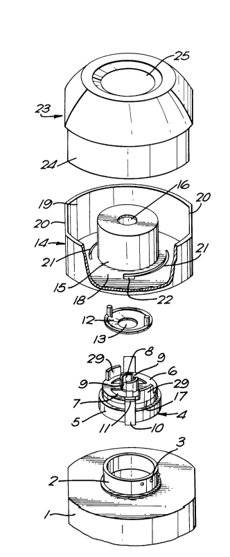
Referring to Figure 1 there is shown part of the top
a container 1 having a neck 2 provided with a series of
retaining protrusions 3. The closure 4 comprises an
annular body 5 having on its inside surface retaining
protrusions (not shown) which cooperate with the
protrusions 3 to retain the closure in a fixed relative
position on the container neck 2.
2s The top of the closure is formed by an end wall 6
having arcuate openings 7 therethrough and a central
upstanding annular collar 8 interrupted by two
longitudinal gaps 9.
Extending outwardly from the closure are 'L' shaped
support arms 10 one of which is shown more clearly in
Figure 2 and which carry at their free ends outwardly
extending lugs 11 disposed in a plane above the connection
of the support arms with the closure.
2013969
- 7 - C3246
A flexible diaphragm 12 has an aperture 13 which
allows the diaphragm to pass over the annular collar 8 of
the closure.
The diaphragm 12 is retained in position on the
closure 4 by a closing member 14 which has a central
collar (not shown) within an annular body portion 15
which collar is a sliding fit within the collar 8, gaps in
the collar of the closing member having a width narrower
o than the width of the collar parts 8. The collar on the
closing member is hollow and forms an outlet opening 16 in
the top of the body portion of the closing member. The
closing member is rotatably secured to the closure 4 by an
internal annular rib within the body portion 15 (not
shown) which engages with an annular groove 17 on the
outside of the annular body 5 of the closure 4. A
substantially annular flange 18 extends outwardly from the
body portion 15 and has at its outer periphery an
upstanding skirt 19 which is non-circular in that it is
provided with two opposite straight sections 20. The
peripheral flange 18 is provided with two arcuate slots 21
each having at one end an opening 22 large enough to allow
a lug 11 to pass therethrough.
2s
A transparent overcap 23 has a plug portion 24
adapted to be a push fit within the skirt 19 of the
closing member, the top of the overcap being recessed at
25. As seen in Figure 3 the underside of the overcap has
30 an inwardly projecting flange 26 surrounding an opening 27
which can pass over the body portion 15 of the closing
member, the opening being shaped at 28 to allow the lugs
ll to also pass therethrough.
The closing member 14 is snappingly engaged to the
closure with the diaphragm 12 therebetween by aligning the
2013969
- 8 - C3246
openings 22 in the annular flange 18 with the lugs 11.
With the closing member thus engaged with the closure 4
the resilient diaphragm 12 seals the arcuate openings 7 in
the closure when the internal pressure in the container is
substantially ambient pressure. In the open position of
the closing member the gaps 9 in the collar 8 coincide
with the gaps in the collar of the closing member. When
the internal pressure in the container 1 is increased, eg.
by squeezing the container 1, the diaphragm lifts to allow
lo contents to pass through the arcuate openings 7, through
the gaps in the collars and out of outlet 16. In the
closed position the gaps in the respective collars are
closed by the collar parts of the other members to prevent
contents being discharged irrespective of the container
internal pressure.
Rotation of the closing member 14 relative to the
closure is permitted by the support arms 10 moving in~the
arcuate slots 21. The closing member is permitted to
rotate relative to the closure through approximately 90
between the open and closed positions by stop members 29
extending upwardly from the closure 4 which engage with
stops (not shown) within the body portion 15 of the
closing member.
The overcap 23 can only be mounted on the closing
member in one of two relative positions by virtue of the
straight sections 20 on the skirt 19. Further, the
overcap can only be removed and replaced on the closing
member when portions 28 of the openings in the overcap
coincide with the lugs 11. When these two conditions are
met the closing member is in the closed position, ie. the
gaps in the collar of the closing member 14 being aligned
with the collar parts 8 of the closure 4. The plug
portion 24 of the overcap can then be fully inserted
2013969
- 9 - C3246
within the skirt 19 of the closing member and rotated
together relative to the closure thereby opening the
closure. Simultaneously the lugs 11 engage over the
flange 26 to lock the overcap in position surrounding the
closure and prevent the overcap from being removed.
The container can be stored with the overcap
assembled on the closing member and held thereto by the
push fit of the plug portion 24 in the skirt 19. In this
lo condition the closing member is in the closed position so
that the contents cannot be discharged through the outlet
16 into the overcap. The container can be stood on the
overcap with the container uppermost so that the contents
of the container are at the container neck 2 adjacent to
the closure.
To dispense a required dose of the contents of the
container into the overcap the overcap is rotated relative
to the container thus rotating the closing member rel`ative
to the closure to open the closure by bringing the gaps 9
of the the collar 8 on the closure into alignment with the
gaps of the central collar of the closing member. This
rotation also serves to lock the overcap to the container
by the bayonet - like engagement of the lugs 11 over the
flange 26. In this condition a dose of-the container
contents can be discharged from the container through the
closure into the overcap by squeezing the container to
increase the internal container pressure and move the
flexible diaphragm 12 to open the arcuate openings 7.
When the required dose is present in the overcap, as
conveniently observed through transparent walls of the
overcap, the overcap is rotated to the original position
to bring the gaps 9 in the collar 8 of the closure
opposite the collar of the closing member to close the
closure. The overcap can then be released from the
2013969
- 10 - C3246
container and the dose used as desired. Whilst using the
dose in the overcap the container can be stood on the foot
provided by the skirt 19 of the closing member. Whilst
the overcap is removed contents cannot be discharged from
the container since the closure is closed.
Whilst the invention has been described with
reference to a flexible container having a closure
incorporating a resilient diaphragm sealing the closure
o and responsive to internal container pressure to open the
closure the invention can also be employed with closures
which do not incorporate such pressure operable sealing
means. The pressure operable sealing means provides a
degree of control over the discharge of a dose of the
container contents into the overcap but if the liquid
contents are sufficiently viscous the closure can comprise
opening and closing means operated by movement of the
closing member, eg. an iris or apertures in the closure
and closing member which are moved into and out of
alignment by movement of the closing member relative to
the closure.
The invention also provides a particularly convenient
method of dispensing a dose of a liquid detergent
- composition. Certain such compositions are sensitive to
small quantities of water and it is therefore desirable to
prevent water entering the container. Thus a dispensing
device as described above and shown in the accompanying
drawings can be used to dispense a dose of liquid
detergent from a container into an overcap, which overcap
serves as a dosing device that can be placed directly in
the tub of a washing machine to dispense the contents
during the washing cycle. During the washing cycle the
container can be safely left with the overcap removed
without any risk of spillage or water entering the
201396~
~ C3246
container through the closed closure. Moreover if the
container is stood during this time on the foot formed by
skirt on the closing member the risk of water being
splashed onto the closure is minimised. After the washing
S cycle has been completed the overcap can be retrieved,
dried if necessary, and replaced on the closing member to
prevent it being mislaid and to provide additional
security against spillage or contamination of the
remaining contents of the container.