Note: Descriptions are shown in the official language in which they were submitted.
. l - e s ~ 1 6 ~ ~ i 8 6 ~ ~
ZQ~4~
ARTIC~1LATED MULTI-UNIT HOPPER RAIL~AY CAR
BACKGROUND OF T~IE INVENTION
Field of the Invention
. .
This invention relates to railway cars and particularly
to an articulated multi-unit railway car capable of optimum
efficiency in operation.
Description of the Prior Art
~ opper cars have long been used in the railroad industry
to transport bulk commodities, such as minerals, grain,
certain chemicals and the like. Typically, a hopper car
includes a covered or open top, through which the transported
material is loaded, and a botton~ discharge system. Bulk
materials of the type previously described are predominantly
transported in one hundred ton hopper cars having cubic
capacities suitable for the densities of the commodities to
be carried. The empty weights of those cars vary according
to their volumetric capacities. The largest of the one
hundred ton covered hopper cars in the United States and
Canadian railcar fleets used to transport the materials
previously described possess a volumetric capacity of 4,550
to 4,750 cubic feet. Open top hopper cars have volumes of
3,600 cubic feet up to ~,200 cubic feet. The empty weight of
these large cars is in the range of 60,000 to 65,000 pounds.
A hundred ton hopper car of such designs can be loaded to a
gross weight of 263,000 pounds. The weight carrying capacity
of each car is the difference between the gross
weight~on-rail and empty car weight; therefore, cars having
an empty weiyht of 60,000 to G5,000 pouncls have respective
2~ r~
carrying capacities of 203,noo to 198,000 pounds. A standard
hopper car generally is a relatively long vehicle, such as
having an overall coupler to coupler length of about 60 feet
and a length of 45'-9" between truck centers. Because
railroad clearances for right of ways in the United States,
Mexico, and Canada are defined by Association of A~erican
Railroads (AAR) clearance diagrams, the width of a standard
hopper car having the foregoing truck center length is
restricted to 10'-5%".
One hundred ton covered hopper cars are equipped with
industry approved standard components, including two each 100
ton three piece trucks, two each draft rigging sill
assemblies with couplers, and one set of body mounted or
truck mounted airbrake systems. The cars are also
constructed with straight or curved sides, trough-type or
round roof openings for loading, and sloping bottoms leading
to three or four outlet gates for unloading. The
conventional cars are further equipped with safety devices or
appliances such as ladders, handbrakes, unco~pling rods, sill
steps, roof running boards or walkways, crossover platforms,
all designed and built to meet the requirements of Federal
Railroad Administration (FRA) standards. The underframe
construction is either a through center si~l or shear plate
and stub sill design. The underframe of such known hoppers
incorporate the use of transverse body bolsters and
longitudinal side sills that extend the length of the car for
proper distribution of dead and live loads imposed on the
structures. These cars are designed and built for
interchange service between railroads and conform to standard
;~Q140~i~
specifications formulated by the AAR. The foregoing cars
have been the industry standard for the transportation of
bulk commodities since the early 1960s. Open top hopper cars
have a similar design except for the elimination of the roof
and associated equipment.
An indicative evaluation of the carrying capacity of a
hopper car for bulk commodities is determined by computing
the ratios of volume to lightweight, and load limit to
lightweight. For a standard covered hopper car having a
volume of 4,750 cubic feet and weighing 63,0~0 pounds, the
volume to lightweight ratio is 0.0754 and the load limit to
lightweight ratio is 3.175. In addition, these known hopper
cars provide an approximate load limit to length ratio (i.e.
200,000 lbs./60 feet) of 3333.0 and a volume/len~th ratio
(4,750 cu. ft./60 feet) of 79.2. The foregoing efficiencies
and factors have been the generally expected limit for
existing hopper cars. The railroad industry has become aware
of the critical need to reduce the initial capital investment
cost as well as day to day operating costs of its e~uipment.
The previously described hopper cars, such as of the one
hundred ton design, suffer serious drawbacks when considering
the relative cost of the eyuipment and the oveeall efficiency
of operation. There exist numerous areas from a operational
standpoint in which improvements in efficiency should be
highly desired by the industry. For example, known covered
hopper cars possess an inefficient aerodynamic design and
excessive weight that results in fuel inefficiency.
The maintenance cost for standard covered cars is also
Z(~40t;3
undesirably high. Costly maintenance can be directly
attributed to the standard number of components in the
design, such as the number of trucks and the ]ike, that are
required in a trainset of a large number of cars as is
common. Existing hoppers have also demonstrated a relatively
poor accident record, increasing costs by virtue of damage to
the equipment and subsequent lading losses. All of the
foregoing factors have a significant impact on the expected
operating expense of standard hopper cars. Manufacturing
costs of hopper cars as currently used are further dependent
on the size and weight of the equipment for a ~iven trainset.
Because of the inherent design of current hopper cars, there
is little hope of making any significant impact on the costs
of manufacturing and maintenance. Accordingly, a critical
need exists in the industry for new designs of hopper cars
for carrying commodities that offer real savings in
manufacturing and operating costs.
S~MMARY OF THE INVENTION
It is an ob~ective of the present invention to reduce
the costs of manufacturing and operating hopper cars for
carrying lading, generally in the form Or bulk commodities.
The apparatus herein disclosed is directed to articulated
covered hopper cars having opposite end units and a plurality
of interMediate units. The teachings of the invention can
also be applied to open top hopper cars. It has been
discovered that the use of three intermediate units provides
unexpected economy in manufacture and operation, although
other number of multiple intermediate units may be used in
2(~40~i9
accordance with the invention. The inboard ends of the end
units and intermediate units are interconnected by
articulated connector assemblies. The outboard ends of each
end unit is fitted with standard couplers, body bolsters,
body side bearings and body centerplates. The inboard ends
of the end units have an identical construction as the ends
of the intermediate units which differ from the design of the
outboard ends. The inboard ends of the end units and the
ends of the intermediate units employ an improved
construction generally including a torsion box, center sills,
and unique body side bearing extension arm assemblies for the
shared truck assemblies. The foregoing extension arm
assemblies permit the elimination of two truck side bearing
assemblies at each unit connection with resulting closer
spacing between units.
The multi-unit articulated hopper cars of the invention
are intended for unit train operations. Because of the
design of the articulated hopper cars herein disclosed, the
underframes are designed to result in light weight end and
intermediate units. Such a light weight structure is
attained in part because each separate unit of the
articulated car is shorter (i.e. approximately 27' to 28'
between truck centers) than standard hopper cars (45'-9"
between truck centers) that allows a lighter construction to
withstand live~ dead, and impact loads. The short truck
centers also permit the car to be designed to the maximum AAR
clearance width ~i.e. 10'-8") for optimum volumetric
capacity. This width is greater than the width of standard
cars. The invention also permits the use of two lighter
Z(~140~9
weight trucks, such as a 70 ton design on the outboard ends
of end units, while heavier capacity truck assemblies, such
as of a 125 ton design, can be shared by an end unit and
intermediate unit or shared by two intermediate units. The
decrease in car unit length and truck centers in the
invention permits the car body to be designed lower to the
top of the rails as determined by vertical curve negotiation
calculations. A lower body results in a design of maximum
volume within a given length, width, and height envelope and
a lower center of gravity. The effect of the light body
weight and truck utilization improves load carrying capacity
(load limit/lightweight) over a standard hopper car by a
significant 27 per cent when using a five unit articulated
covered hopper car in accordance with the invention. For
example, a comparable five-unit car as herein disclosed
achieves an improved volume/lightweight ratio of 0.0916 and
load limit/lightweight ratio 4.021 as compared to 0.0754 and
3.175, respectively, for a standard 100 ton covered hopper
car. Moreover, a five unit articulated car of the invention
as previo~sly discussed attains a load limit to coupler-to-
coupler length ratio (i.e. 680,700 lbs/ 152.51 ft) of
approximately 4463.00 and volume/ length (i.e. 15,500 cu.
ft./ 152.51 ft.) of about 102.0, improving the same ratios of
standard hopper cars by approximately 33.9% and 28.30%
respectively. Similar efficiencies can be attained for open
hopper cars constructed in accordance with invention.
The foregoing improvement in efficiency ratios is
particularly impressive when the articulated covered hopper
cars of the invention are compared to standard 100 ton hopper
--6--
4Q~!~
cars having a capacity of 4 750 cubic feet. In cubic
capacity, thirty articulated covered hopper cars, having five
units each and constructed in accordance with the invention
(i.e. cubic capacity of the end units being 3,248 cubic feet
and intermediate units having a capacity of 3,002 cubic feet
each), virtually equals the the volumetric capacity of ninety
eight 100 ton standard hopper cars (4,750 cubic feet). A
trainset of thirty such articulated cars of the foregoing
capacity possesses an overall lenyth of 1300 ~eet less than
ninety eight 100 ton standard hopper cars. Since drag is
dependent on train length, the articulated design of the
invention therefore produces significantly improved
aerodynamic performance and fuel savings over known designs.
Further, the empty weight of a trainset as previously
described in accordance with the invention weighs
approximately 1.1 million pounds less than ninety-eight 100
ton standard hopper cars. The lighter weight permits an
additional loading of 1.1 million pounds more than standard
cars up to the maximum now permitted. The design of the
invention, again comparing a thirty car trainset of the type
herein disclosed and ninety eight standard cars, requires
fewer car components, namely 16 fewer trucks, 32 less axles,
64 less roller bearings, 64 less wheels, 64 less brake shoes,
136 less draft rigging assemblies, 8 less brake schedules, 38
less handbrakes, 136 less ladder assemblies, 136 less
crossover steps, and 92 less trough hatch covers. Through
elimination of the foregoing car components, it is expected
that maintenance expense of the articulated cars of the
invention will be reduced by a very significant savings of 15
2Q~4~9
to 20 per cent. It is also apparent from the foregoing
reduction of car components that manufacturing costs will be
greatly less than standard hopper cars.
BRIEF DESCRIPTION OF THE ~RAWINGS
.
Fig 1 is a side elevational schematic view of the
multi-unit articulated covered hopper car of the invention;
Fig 2 is a side elevational view, with parts in section,
of an end unit of the articulated covered hopper car of Fig.
l;
Fig 3 is a top plan view, with parts in section, of the
end unit of Fig. 2;
Fig 4 is an elevational view of the outboard end of the
end unit of Fig. 2;
Fig 5 is a sic]e elevationa] view, with parts in section,
of an intermediate unit of the multi-unit articulated hopper
car of Fig. l;
Fig 6 is a top plan view, with parts in section, of the
intermediate unit of Fig. 5;
Fig 7 is an end elevational view, with parts in section,
of the intermediate unit of Fig. 5.
Fig. 8 is a partial side elevational view, with parts in
section, of the articulated connector assembly for connecting
two intermediate units of the mult-unit articulated hopper
car of the invention;
Fig. 9 is a partial side elevational view of one of the
body side bearing extension arm assemblies used in
conjunction with the articulated connector assembly of Fig. 8
2(~063
shown between adjoining intermediate units; and
Fig. ]0 is a partial elevational end view, with parts in
section, of the body side bearing extension arm assembly of
Fig. 9 taken along lines 10-10.
DESCRIPTION OF A PREFERRED EMBODIMENT
Referring now to Figs. 1 to 10, there is illustrated the
multi-unit articulated covered hopper car of the invention,
generally designated by reference numeral 2. The articulated
car 2 is intended to be used to transport bulk commodities of
many kinds and comprises a pair of identical end units 4 and
a plurality of intermediate units 6. Although other number
of intermediate units can be employed in accordance with the
teachings of the invention, it has been found that the use of
three intermediate units 6 as shown in Fig. ] is particularly
efficient from the standpoint of manufacturing and operation
as was previously discussed. ~urther, it should be noted
that although articulated car 2 is illustrated as a covered
hopper car, it is within the scope of the invention to apply
its teachings to open top hopper cars as used with certain
commodities.
Referring again to Fig. 1 the outboard ends of end unit
4 are suppported by truck assemblies 8. The inboard ends of
the intermediate units 6 share a truck assembly 10 in common,
symetrically arranged with an adjacent end unit 4 or an
adjacent intermediate unit 6. In the five unit articulated
car 2 of Fig. 1, two truck assemblies 8 and four truck
assemblies 10 are utilized, with each truck assembly
2~40~9
including four wheels. As seen in Fig. 1, the outboard ends
of end units 6 possess a standard design and are provided
with conventional couplers 12. The inboard ends of the end
units 4 are connected to the adjoining intermediate unit 6 by
an articulated connector assembly 14. An identical
articulated connector assembly connects the intermediate
units 6 to each other. The articulated connector assemblies
14, with other structure to be described, permit closer
spacing of the inboard ends of the end units 4 with an
adjacent intermediate unit 6 and between adjacent
intermediate units 6 than permitted by standard couplers 12.
Such closer spacing results in significant reductions in
train weight and length and, hence drag, as compared to
conventional cars in which standard couplers are used between
each car.
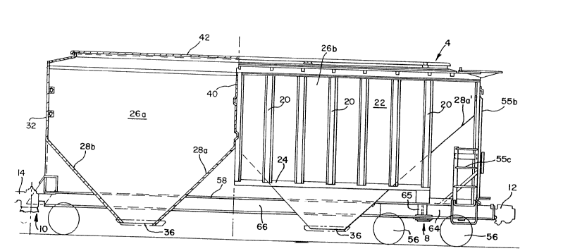
Referring now to Figs. 2-4, details of the right end
unit 4, when viewing Fig. 1, are shown. The end unit 4 shown
in Figs. 2-4 has an identical construction as the opposite
end unit 4, except with a reversed longitudinal arrangement
of the components and variation of the male/female connectors
used in articulated connector assemblies 14. The inboard
ends of each end unit 4 has the corresponding cooperating
components as both ends of the intermediate units 6 as will
be described, while the outboard ends of the end units 4
differ by each including the standard coupler 12. The end
unit 4 is formed with a body having side posts 20 and
vertical side sheets 22 carried by a pair of longitudinally
extending side sills 24. A pair of hoppers 26a, 26b for
carrying commodities are suitably supported by known
--10--
2Q~069
techniques positioned within the side sheets 22. Lower
hopper floor sheets 28a, 28b, 28c, and 28d, which are
suitably supported, of the hopper 26 (Figs. 2 and 3) are
sloped at an angle. The hopper floor sheet 28a' of the
outboard hooper 26b possesses a longer length than the floor
sheet 28a as seen in Fig. 2. End walls 32 are arranged above
the floor sheets of hoppers 26a,26b. The hoppers 26a, 26b
terminate with discharge gates 36 at their respective bottoms
extending beneath the side sills 24. A vertical partition
sheet 40 is mounted above the sloped floor sheet 28a to
retain the lading in a particular hopper.
The top of the end unit 4 is covered by a roof sheet 42
having a dome configuration upon which typical running boards
44 and end running boards 46 are fitted as best seen in Fig.
2-4. An elongated trough opening 50 (a portion of which is
shown in Fig. 3) for receiving commodities is formed in the
roof sheet 42 and is arranged to be covered by a hatch cover
52 that extends, for example, for approximately 80% of the
length of the end unit 4. The trough opening 50 having a 24
inch width and rounded ends has been found to be suitable in
the invention. The hatch cover 52 is conventionally retained
by hatch cover battens 54. Conventional end ladders 55a, 55b
and 55c are provided on the outboard end of end unit 4.
~ Again referring to Figs. 1,2, and 4, the truck assembly
- 8 is positioned beneath the outboard end of end unit 4 and is
of a standard three piece design including a conventional
bolster and side frames (not shown). The truck assembly 8
includes four wheels 56 disposed beneath the outboard end of
2{~140~i9
end unit 4. A draft sill 64 having a conventional cross
section supports a striker 68 and conventional coupler
assembly 12 of a well known semi-automatic design. A body
bolster 65 of known design is carried by the draft sill 64.
The draft sill 64 extends from the coupler assembly 12 to a
point inboard of body bolster 65. The inboard end of the
draft sill 64 interconnects with a center sill 66 that
extends to the inboard end of end unit 4. The center sill 66
is identical in cross section as the center sills of the
intermediate units 6 to be described. For sake of example
without limitation as to the capacity of the truck assembly,
the outboard truck assembly 8 may have a capacity of 70 tons,
when the volume of the end unit 4 is 3,248 cubic feet. The
structure of the inboard ends of end unit 4 will be apparent
from the following description of the intermediate unit 6.
Referring to Figs. 5-10, there is illustrated one of the
intermediate units 6 of the multi-unit articulated covered
hopper car 2 as shown in Fig. 1. Each of the intermediate
units 6 has the identical components as illustrated in Figs.
5-10. The intermediate units 6 include a pair of side sills
100, side posts 102, and side sheets 104 similar to the end
unit 4, although the length of each of the intermediate units
6 may be less. The interior of intermediate unit 6 is
provided with two identical hoppers 106 shown having a
smaller volumetric capacity than the hoppers of end unit 4.
By way of example, the hoppers 106 of intermediate units 6
may have a total capacity of 3,002 cubic feet. It is within
the scope of the invention, however, to vary the comparative
sizes o~ the hoppers in the end units ~ and the intermediate
-12-
2(~ 4069
units 6. The hoppers 106 include reinforced sloped floor
portions 107a,b,c, and d that terminate with discharge
openings 108. The hoppers 106 are loaded through upper
trough opening 110 formed in roof sheet 111 and having
rounded ends and extending for a length of greater than 70
per cent of the intermediate unit 6. The trough opening 110
having a 24 inch width and rounded ends has been found to be
suitalbe in the invention. The trough opening 110 is covered
by hatch cover 112. Cross over running boards 114 and side
running boards 116 are positioned on the roof 111 adjacent
through opening 110. Hatch cover battens 118 are used to
retain the hatch covers 112 in place.
Hopper discharge chutes 126 forming opening 108 are
disposed beneath the side sills 100 and are fitted with
typical discharge gates 128. An upper bolster web 134 in the
form of an end wall is mounted at each end of the
intermediate unit 6 beneath a respective hopper 106. The
upper bolster web 134 is carried by a laterally extending
torsion box/end sill 136 extending substantially the width of
intermediate unit 6 at each end. A pair of triangular
gussets 137 connect a hopper floor sheet with bolster web
134, torsion box 136, and center sill 140. Center sill 140
extends the length of the intermediate units 6 and has the
hollow box cross section as shown in Fig. 7. The center sill
140 is attached at each end of intermediate unit 6 to a
underside of torsion box 136.
Two wheels 149 of the truck assembly 12 carrying
intermediate unit 6 are disposed respectively under a pair of
-13-
2n~40~i3
adjoining ends of intermediate units 6. The truck assembly
12 includes typical bolsters and side frames (not shown)
supported beneath the ends of adjoining intermediate units 6
in a well known manner. For sake of example, each truck
assembly 12 may have a capacity of 125 tons. Each truck
assembly 12 of intermediate units 6 is equipped on opposite
sides of center sill 140 with a pair of truck side bearing
housing assemblies 150, one of which is shown in Fiqs. 9 and
10. A pair of side bearing rollers 152 (Fig. 9), or
alternatively a constant contact type side bearing (not
shown), are mounted in bearing housing assembly 150. A body
side bearing extension arm assembly 154, comprising a mating
female extension arm 156 and male extension arm 158, are
nested on the top of each truck side bearing housing assembly
150. The female extension arm 156 extends in parallel
relationship to the longitudinal centerline of intermediate
unit 6 and includes a base 161 and two opposed vertical walls
162 forming an opening 164. The two side walls 162 angularly
extend upward from base 161 to an upper edge 166 being shaped
to engage the torsion box 136 in welded attachment.
The male extension arm 158 includes a base 170 that
bears against the base 161 of the female extension arm 156
through shims and wear plates. A pair of spaced arm members
172 project angularly upward from base 170 upward through
opening 164 of the female arm section 156. The upper edges
176 of the male arm section 174 are shaped to engage torsion
box 136 on the opposed intermediate unit 6 in welded
engagement. As seen in Fig. 10 the outer surfaces 178 of
spaced arm member 172 are spaced from the inner surfaces of
Z(~140~i9
walls 162 of the female extension arm 156 to provide a
clearance 182 on each side. The clearance 182 between the
female extension arm 156 and male extension arm 158 permits
relative rotational movement for curve negotiation during
operation. Further, the unique design of the body side
bearing extension arm assembly 154 allows extremely close
spacing of adjoining intermediate units 6, such as, for
example, a very small distance of 12 inches apart, to achieve
a significant reduction of the length of a given trainset of
articulated hopper cars 2 of the invention. The body side
bearing extension arm assembly 154 permits the use of two
truck side bearings at each connection as opposed to four
side bearings at each connection as utilized in known
articulated connections.
The adjoining ends of intermediate units 6 are
connected by articulated connector assembly 14 as previously
described with reference to Fig. 1. As shown in Fig. 8, the
articulated connector asssembly 14 is of a conventional
design providing a slack-free connection and includes a
cooperating male articulated connector 190 on one of
adjoining intermediate units 6 and a female articulated
connector 192 on the adjacent intermediate unit 6. A pin 194
connects the connectors 190 and 192 as a slack free unit.
The connectors 190 and 192 are attached by a conventional
technique to center sills 140 of opposed intermediate units 6
and are carried on the truck assembly (not shown).
In the foregoing description with reference to Figs.
5-lQ, the cooperating structure between adjoining ends of
intermediate units 6 was described. The inboard ends of end
2~4~9
units 4 correspond identically to the structure and function
of the previously described ends of intermediate units 6,
including the ~se of a shared truck assembly 10, articulated
connector assemblies 14 and body side bearing extension arm
assemblies 154. Thus, the spacing between the inboard end of
an end unit 4 and the adjacent intermediate unit 6 is
similarly as close as the distance between intermediate units
6. From the foregoing it should be apparent that it is
advantageous for interchangeability for a female extension
arm 154 and male extension arm 156 be mounted on opposed ends
of each intermediate unit 6. Similarly, a female arm
assembly and male arm must be respectively situated on the
inboard ends of the opposite end units 4.
-16-